

Wedge Anchor Bolt
1. Industry Context
1.1 Role of Mechanical Anchoring Systems in Industrial Infrastructure
Modern industrial assets depend on reliable load transfer between equipment and structural concrete. The wedge anchor bolt represents one of the most widely accepted mechanical anchoring solutions used across global EPC projects.
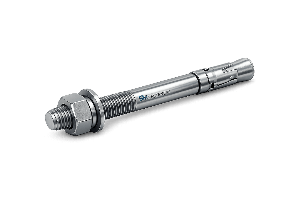
Unlike conventional threaded fasteners that clamp two components together, wedge anchors function as load-transferring structural connectors between:
- Steel structures
- Machinery baseplates
- Process equipment skids
- Pipe supports
- Cable tray systems
- Safety barriers
- Offshore modules
They convert installation torque into radial expansion force, creating mechanical interlock with hardened concrete.
Primary engineering requirement:
Achieve predictable load capacity under static, dynamic, seismic, and fatigue conditions while maintaining long-term reliability.
1.2 Global Industrial Drivers
The demand for wedge anchor bolts continues to increase due to:
| Industrial Driver | Engineering Requirement |
|---|---|
| High-rise infrastructure | High pull-out resistance |
| Modular construction | Rapid installation |
| EPC mega projects | Standardized anchoring systems |
| Offshore installations | Corrosion resistance |
| Renewable power plants | Fatigue resistance |
| Heavy equipment foundations | Vibration stability |
SM Fasteners supplies wedge anchor systems aligned with global industrial installation practices, supporting projects across construction, energy, petrochemical, rail, and marine sectors.
1.3 Position of Wedge Anchors Among Anchor Technologies
| Anchor Type | Installation Principle | Load Capacity | Typical Use |
|---|---|---|---|
| Wedge Anchor | Mechanical expansion | Very High | Structural anchoring |
| Sleeve Anchor | Expansion sleeve | Medium | Light structural |
| Chemical Anchor | Adhesive bonding | Very High | Cracked concrete |
| Drop-in Anchor | Internal expansion | Medium | Suspended systems |
| Toggle Anchor | Backside clamping | Low | Hollow materials |
Wedge anchors are preferred where:
- Base material is solid concrete
- Immediate loading is required
- Predictable torque-controlled installation is necessary
2. Technical Definition
2.1 Engineering Definition
A Wedge Anchor Bolt is a torque-controlled mechanical expansion fastener consisting of:
- Threaded stud
- Expansion clip (wedge)
- Nut
- Washer
When tightened, axial movement forces the wedge clip outward, generating radial expansion pressure against the drilled concrete hole.
2.2 Primary Components
| Component | Function |
|---|---|
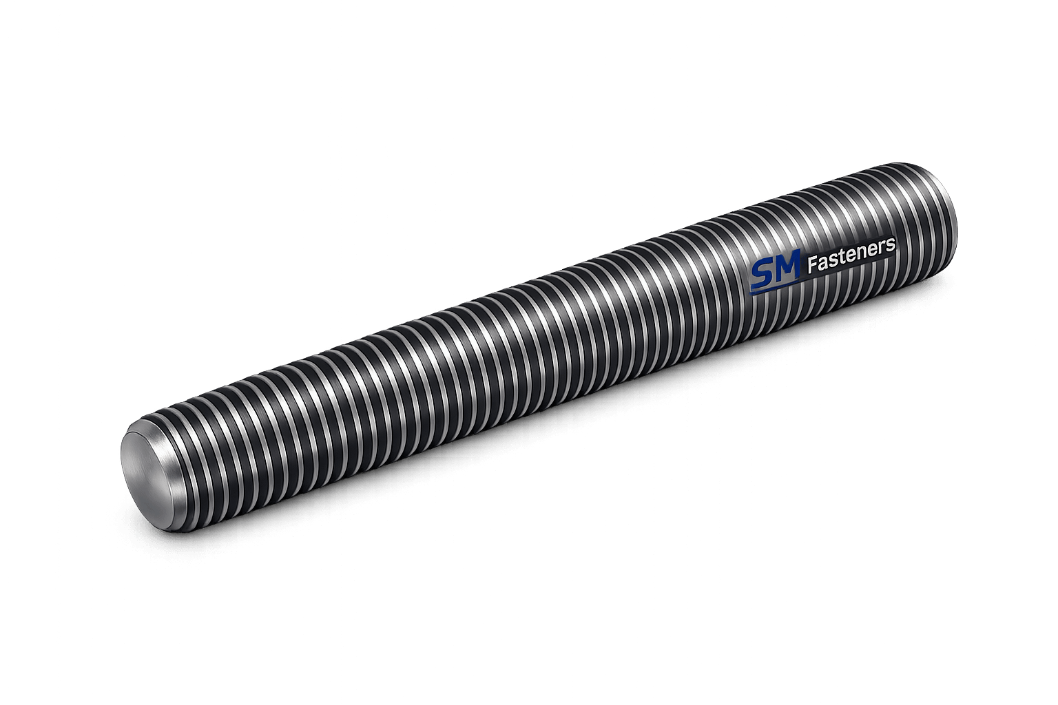
| Threaded Stud Fully Threaded Stud | Transfers tensile load |
| Expansion Clip | Produces radial expansion |
| Nut | Applies installation torque |
| Washer | Distributes clamping load |
| Chamfered Tip | Enables insertion into drilled hole |
2.3 Functional Principle
Installation sequence:
- Hole drilled to specified diameter.
- Anchor inserted through fixture.
- Nut tightened to installation torque.
- Clip expands against concrete.
- Friction + mechanical interlock develops.
The system relies on:
- Radial compression
- Frictional resistance
- Concrete bearing strength
2.4 Fundamental Design Concept
The wedge anchor operates on the principle:
Where:
- Applied torque creates axial tension.
- Axial tension drives wedge expansion.
- Expansion generates anchorage resistance.
3. Load Mechanics & Force Behaviour
Understanding load mechanics is essential for structural engineers and procurement teams selecting anchoring systems.
3.1 Types of Loads Acting on Wedge Anchors
1. Tensile Load (Pull-Out)
Acts along bolt axis.
Sources:
- Equipment uplift
- Wind loading
- Pipe thrust forces
- Seismic uplift
Failure Modes:
- Concrete cone failure
- Steel tensile fracture
- Pull-out slip
2. Shear Load
Acts perpendicular to bolt axis.
Typical Sources:
- Equipment sliding forces
- Structural lateral loads
- Impact loading
3. Combined Loading
Most industrial installations experience:
Where:
- T = tensile force
- V = shear force
Engineering evaluation must consider interaction ratios.
4. Dynamic & Fatigue Loading
Critical for:
- Rotating machinery
- Pumps
- Compressors
- Offshore equipment
- Railway structures
Key requirement:
Maintain preload to prevent joint separation.
3.2 Load Transfer Mechanism
Load transfers through three sequential paths:
- Fixture → Washer → Nut
- Stud → Expansion Clip
- Clip → Concrete Interface
Proper installation torque directly controls system performance.
3.3 Concrete Interaction Behaviour
Concrete response governs anchor performance.
Stress Zones
| Zone | Description |
|---|---|
| Compression Zone | Around expansion clip |
| Shear Cone | Load dispersion region |
| Failure Cone | Potential breakout area |
Typical failure cone angle ≈ 35°–45°.
3.4 Pull-Out Resistance Theory
Simplified resistance:
Where:
- = concrete compressive strength
- = effective embedment depth
- k = geometry factor
Engineering implication:
Embedment depth has exponential influence on capacity.
3.5 Influence of Installation Torque
Torque controls:
- Preload
- Expansion force
- Friction coefficient
- Long-term reliability
Under-torque → Insufficient expansion
Over-torque → Concrete cracking or bolt yielding
3.6 Torque–Tension Relationship
Where:
- T = torque
- K = nut factor
- D = nominal diameter
- F = preload force
Typical nut factor values:
| Surface Condition | Nut Factor (K) |
|---|---|
| Dry | 0.20–0.25 |
| Zinc plated | 0.18 |
| Lubricated | 0.15 |
| PTFE coated | 0.10–0.13 |
3.7 Preload Importance
Proper preload ensures:
- No joint separation
- Vibration resistance
- Fatigue life improvement
- Load sharing across anchors
Engineering guideline:
3.8 Friction and Expansion Mechanics
Two friction interfaces exist:
- Thread friction
- Concrete interface friction
Approximate torque distribution:
| Energy Use | Percentage |
|---|---|
| Thread friction | 40% |
| Bearing friction | 50% |
| Useful preload | 10% |
This highlights the importance of controlled lubrication and coating selection.
3.9 Edge Distance & Spacing Effects
Improper placement drastically reduces capacity.
| Parameter | Effect |
|---|---|
| Small edge distance | Concrete splitting |
| Close spacing | Overlapping stress cones |
| Excess embedment | Installation difficulty |
Typical engineering recommendation:
- Edge distance ≥ 1.5 × embedment depth
- Spacing ≥ 3 × anchor diameter
3.10 Concrete Condition Influence
Anchor performance varies significantly with substrate condition.
| Concrete Condition | Impact |
|---|---|
| Cracked concrete | Reduced pull-out capacity |
| High-strength concrete | Increased expansion efficiency |
| Lightweight concrete | Lower shear capacity |
| Wet concrete | Possible friction reduction |
3.11 Failure Mechanisms
1. Steel Failure
- Tensile rupture
- Shear fracture
2. Concrete Failure
- Cone breakout
- Edge splitting
3. Installation Failure
- Over-torque damage
- Incorrect hole diameter
- Dust contamination
4. Environmental Failure
- Corrosion expansion
- Hydrogen embrittlement
- Stress corrosion cracking
3.12 Seismic Behaviour Considerations
Seismic design requires:
- Ductile steel grades
- Adequate embedment
- Controlled spacing
- Crack tolerance
Anchors must maintain load even after cyclic displacement.
4. Joint Design Principles
4.1 Anchored Joint Philosophy
A wedge anchor assembly behaves as a prestressed mechanical joint.
Objective:
Maintain compressive contact between baseplate and concrete at all service loads.
4.2 Typical Anchored Joint Components
- Equipment baseplate
- Grout layer
- Concrete foundation
- Wedge anchor system
Correct design ensures load path continuity.
4.3 Preloaded Joint Behaviour
When preload exceeds service load:
- No relative movement occurs.
- Anchor experiences mainly tensile stress.
- Fatigue life increases significantly.
4.4 Design Checks Required by Engineers
| Design Check | Purpose |
|---|---|
| Tensile resistance | Prevent pull-out |
| Shear resistance | Prevent sliding |
| Interaction equation | Combined loading |
| Concrete breakout | Foundation integrity |
| Steel capacity | Bolt safety |
| Edge distance | Crack prevention |
4.5 Embedment Depth Selection
Embedment depth governs:
- Load capacity
- Crack resistance
- Vibration stability
General engineering guideline:
| Application | Embedment |
|---|---|
| Light equipment | 6–8 × diameter |
| Structural steel | 8–12 × diameter |
| Dynamic machinery | 10–15 × diameter |
4.6 Load Distribution in Multi-Anchor Systems
Multiple anchors rarely share load equally due to:
- Installation tolerance
- Plate stiffness
- Hole clearance
Engineering design must consider eccentric loading effects.
4.7 Temperature Effects
High temperature reduces:
- Steel yield strength
- Concrete compressive strength
- Expansion effectiveness
Material selection must consider service temperature range.
4.8 Vibration Resistance Strategy
Reliable installations require:
- Correct preload
- Hardened washers
- Locking mechanisms
- Controlled torque installation
4.9 Design Integration in EPC Projects
For EPC procurement teams, wedge anchors must integrate with:
- Structural calculations
- Foundation drawings
- Equipment load sheets
- Inspection test plans (ITP)
- Project specifications
SM Fasteners supports engineered anchoring solutions aligned with international project documentation workflows.
4.10 Engineering Selection Summary
Selection of a wedge anchor bolt depends on:
- Required load capacity
- Concrete strength
- Environmental exposure
- Corrosion resistance
- Temperature range
- Installation accessibility
- Inspection requirements
5. Product Types and Variants
Wedge anchor bolts are engineered to satisfy differing load capacities, installation environments, corrosion exposure levels, and structural design philosophies.
SM Fasteners manufactures wedge anchors suitable for EPC-grade structural anchoring applications, not retail fastening use.
5.1 Standard Wedge Anchor Configuration
A conventional wedge anchor consists of:
- Fully threaded stud
- Integrated expansion clip
- Hex nut
- Hardened washer
Installation produces expansion at the embedded end only, ensuring predictable anchoring behavior.
5.2 Major Industrial Variants
5.2.1 Fully Threaded Wedge Anchor
Characteristics
- Threaded along entire length
- Adjustable fixture thickness
- High flexibility for field installation
Applications
- Structural steel columns
- Machinery foundations
- Pipe racks
5.2.2 Partial Thread Wedge Anchor
Characteristics
- Reduced thread exposure
- Improved shear resistance
- Reduced stress concentration
Applications
- Heavy equipment mounting
- Dynamic load environments
5.2.3 Stainless Steel Wedge Anchors
Manufactured from:
- SS304 / A2
- SS316 / A4
- Duplex stainless steels
Used where corrosion protection governs design life.
Applications:
- Offshore platforms
- Marine structures
- Food processing facilities
- Chemical plants
5.2.4 Heavy-Duty Structural Wedge Anchor
Designed for:
- High tensile loads
- Thick baseplates
- Seismic-qualified installations
Features:
- Increased embedment depth
- Heavy expansion clip geometry
- Higher property class steels
5.2.5 Seismic / Dynamic Load Anchor
Engineered for:
- Earthquake zones
- Rotating machinery
- Fatigue-prone systems
Design attributes:
- Ductile material grades
- Controlled expansion force
- Crack tolerance performance
5.2.6 High-Temperature Alloy Wedge Anchors
Manufactured from:
- Inconel
- Incoloy
- Hastelloy
- Nickel alloys
Applications:
- Gas turbines
- Refineries
- LNG terminals
- Furnace structures
5.2.7 PEEK-Based Non-Metallic Anchoring Systems
SM Fasteners supports advanced polymer solutions including PEEK fasteners where required:
- Electrical isolation
- Chemical resistance
- Lightweight assemblies
- MRI / non-magnetic environments
Typical sectors:
- Semiconductor
- Medical systems
- Chemical instrumentation
6. Dimensional Logic and Geometry
Wedge anchor performance is governed primarily by geometry rather than material alone.
6.1 Fundamental Geometrical Parameters
| Parameter | Symbol | Engineering Function |
|---|---|---|
| Nominal Diameter | d | Load capacity driver |
| Effective Embedment | hef | Pull-out resistance |
| Hole Diameter | dh | Installation clearance |
| Thread Length | Lt | Fixture accommodation |
| Overall Length | L | Installation flexibility |
| Expansion Length | Le | Radial force development |
| Washer Diameter | Dw | Load distribution |
6.2 Dimensional Specification Table (Metric Series)
Table — Standard Metric Wedge Anchor Dimensions
| Size | Thread Pitch | Drill Hole Ø (mm) | Min Embedment (mm) | Std Length Range (mm) | Washer OD (mm) |
|---|---|---|---|---|---|
| M6 | 1.0 | 6 | 35 | 45–80 | 12 |
| M8 | 1.25 | 8 | 40 | 60–120 | 16 |
| M10 | 1.5 | 10 | 50 | 75–150 | 20 |
| M12 | 1.75 | 12 | 60 | 90–200 | 24 |
| M16 | 2.0 | 16 | 75 | 120–300 | 30 |
| M20 | 2.5 | 20 | 90 | 150–350 | 37 |
| M24 | 3.0 | 24 | 110 | 200–450 | 44 |
| M30 | 3.5 | 30 | 130 | 250–500 | 56 |
Dimensional ranges align with international EPC installation practice and SM Fasteners manufacturing capability.
6.3 Imperial (UNC/UNF) Dimension Logic
| Size | Thread Type | Drill Hole | Embedment |
|---|---|---|---|
| 1/4″ | UNC | 1/4″ | 1-3/8″ |
| 3/8″ | UNC | 3/8″ | 1-1/2″ |
| 1/2″ | UNC | 1/2″ | 2-1/4″ |
| 5/8″ | UNC | 5/8″ | 2-3/4″ |
| 3/4″ | UNC | 3/4″ | 3-1/4″ |
| 1″ | UNC | 1″ | 4-1/2″ |
6.4 Geometry Influence on Performance
Diameter Effect
Load capacity increases approximately with:
Embedment Effect
Pull-out strength increases non-linearly:
Expansion Clip Design
Critical parameters:
- Clip thickness
- Expansion angle
- Contact surface area
- Hardness differential
SM Fasteners controls expansion clip metallurgy to ensure uniform radial expansion.
6.5 Fixture Thickness Capacity
Maximum fixture thickness:
Allowance includes:
- Nut height
- Washer thickness
- Thread protrusion
6.6 Hole Diameter Tolerance Requirements
| Parameter | Typical Tolerance |
|---|---|
| Drill Diameter | +0.1 mm |
| Hole Depth | +5 mm |
| Perpendicularity | ≤ 3° deviation |
| Cleaning Requirement | Dust-free mandatory |
Improper hole preparation is the leading cause of anchor failure.
7. Applicable International Standards
Wedge anchors must comply with globally recognized standards to ensure interchangeability and inspection acceptance.
7.1 Fastener Material Standards
| Standard | Scope |
|---|---|
| ISO 898-1 | Mechanical properties carbon steel |
| ASTM A307 | Low carbon steel bolts |
| ASTM F1554 | Anchor bolts |
| ASTM A193 | Alloy steel high temperature |
| ASTM A320 | Low temperature service |
| ISO 3506 | Stainless steel fasteners |
| ASTM F593 | Stainless fasteners |
| ASTM F594 | Stainless nuts |
7.2 Anchor Design & Qualification Standards
| Standard | Application |
|---|---|
| ACI 355 | Concrete anchor qualification |
| ACI 318 | Structural concrete design |
| ETAG 001 / EAD | European anchor approval |
| EN 1992-4 | Fastening to concrete |
| ICC-ES AC193 | Mechanical anchor evaluation |
SM Fasteners aligns manufacturing practices to facilitate acceptance under these global engineering frameworks.
7.3 Thread Standards & Tolerances
Engineering Table — Thread Systems
| Thread Standard | Region | Tolerance Class |
|---|---|---|
| ISO Metric | Global | 6g / 6H |
| UNC | USA | 2A / 2B |
| UNF | USA | 2A / 2B |
| BSW | UK | Medium |
| BSF | UK | Fine |
| DIN 13 | Europe | Standard metric |
Interchangeability depends on tolerance compliance rather than nominal size alone.
7.4 Property Class System (Metric)
| Property Class | Yield Strength (MPa) | Tensile Strength (MPa) |
|---|---|---|
| 5.8 | 400 | 500 |
| 8.8 | 640 | 800 |
| 10.9 | 940 | 1040 |
| 12.9 | 1100 | 1220 |
Selection depends on:
- Design load
- Seismic demand
- Temperature exposure
7.5 Dimensional Compliance Standards
Relevant dimensional references include:
- DIN 7970 (Anchor bolts)
- ISO 4014 / ISO 4017 (Hex bolts)
- ASME B18.2.1
- BS 4190
SM Fasteners maintains dimensional inspection traceability under ISO 9001 quality management procedures.
7.6 Interchangeability Considerations
Critical engineering notes:
- Metric and UNC threads are not interchangeable.
- Washer hardness must match property class.
- Nut proof load must exceed stud proof load.
- Expansion geometry varies between manufacturers — qualification testing is required before substitution.
7.7 Engineering Selection Matrix (Variant vs Application)
| Application | Recommended Variant |
|---|---|
| Structural steel erection | Fully threaded carbon steel |
| Offshore structures | SS316 / Duplex |
| Petrochemical plants | Alloy steel coated |
| LNG terminals | Nickel alloy |
| Electrical isolation | PEEK anchor |
| Seismic zones | Ductile high-strength grade |
7.8 Procurement Documentation Requirements
Typical EPC procurement specification includes:
- Standard reference
- Property class
- Material grade
- Coating specification
- Heat treatment condition
- Inspection level
- Certification requirement
SM Fasteners supplies wedge anchors aligned with project-specific procurement datasheets and inspection plans.
8. Material Grades and Selection Criteria
Material selection is the most critical engineering decision affecting:
- Structural reliability
- Corrosion life
- Fatigue resistance
- Temperature capability
- Regulatory compliance
Wedge anchors supplied by SM Fasteners are engineered across full industrial metallurgy ranges, enabling deployment in aggressive environments and safety-critical infrastructure.
8.1 Primary Material Categories
| Material Group | Typical Standards | Core Characteristics |
|---|---|---|
| Carbon Steel | ASTM A307 / ISO 898 | Economical, structural use |
| High Strength Alloy Steel | ASTM A193 B7 | High tensile strength |
| Stainless Steel | ISO 3506 | Corrosion resistant |
| Duplex Stainless Steel | ASTM A182 F51 | High strength + corrosion |
| Super Duplex | ASTM A182 F53/F55 | Offshore resistance |
| Nickel Alloys | Inconel / Monel | Extreme temperature |
| SMO 254 | UNS S31254 | Chloride resistance |
| PEEK Polymer | Engineering polymer | Non-metallic isolation |
8.2 Carbon Steel Anchor Materials
Typical Grades
- Property Class 5.8
- Property Class 8.8
- Property Class 10.9
Applications
- Structural steel anchoring
- Machinery foundations
- Infrastructure projects
Advantages:
- High strength-to-cost ratio
- Excellent machinability
- Reliable expansion performance
Limitations:
- Requires protective coating
- Susceptible to corrosion without treatment
8.3 Alloy Steel Wedge Anchors
Common industrial grades:
| ASTM Grade | Service Condition |
|---|---|
| ASTM A193 B7 | High strength structural |
| ASTM A320 L7 | Low temperature service |
| ASTM A193 B16 | Elevated temperature |
Typical uses:
- Petrochemical plants
- Power generation
- Refinery equipment bases
8.4 Stainless Steel Material Selection
| Grade | Equivalent | Characteristics |
|---|---|---|
| SS304 | A2-70 | General corrosion resistance |
| SS316 | A4-70 | Chloride resistance |
| SS316L | Low carbon | Welded environments |
| 904L | High alloy | Acid resistance |
Preferred where maintenance access is limited.
8.5 Duplex & Super Duplex Anchors
Used extensively in:
- Offshore platforms
- LNG terminals
- Desalination plants
Benefits:
- ~2× strength of austenitic stainless
- Superior resistance to chloride stress corrosion cracking
8.6 Nickel Alloy Anchors
SM Fasteners manufactures anchors in advanced alloys:
- Inconel 625
- Inconel 718
- Hastelloy C276
- Monel 400
- Incoloy 825
Applications:
- Sour gas environments
- Chemical reactors
- High-temperature furnaces
- Marine splash zones
8.7 PEEK Fastener Integration
PEEK anchors are specified where metallic fasteners are unsuitable.
Properties:
- Continuous temperature ≈ 250°C
- Electrical insulation
- Chemical inertness
- Non-magnetic behavior
Used in:
- Semiconductor manufacturing
- Medical equipment
- High purity chemical systems
8.8 Material Comparison Table
Engineering Table — Material Performance Comparison
| Material | Yield Strength (MPa) | UTS (MPa) | Corrosion Resistance | Temp Limit °C | Relative Cost | Typical Application |
|---|---|---|---|---|---|---|
| Carbon Steel 8.8 | 640 | 800 | Low | 300 | Low | Structural anchoring |
| Alloy Steel B7 | 720 | 860 | Medium | 450 | Medium | Power plants |
| SS304 | 450 | 700 | Good | 400 | Medium | Buildings |
| SS316 | 450 | 700 | Very Good | 450 | Medium-High | Marine |
| Duplex F51 | 550 | 800 | Excellent | 300 | High | Offshore |
| Super Duplex F55 | 650 | 900 | Outstanding | 300 | Very High | Seawater |
| Inconel 625 | 460 | 930 | Exceptional | 700 | Premium | LNG |
| SMO 254 | 300 | 650 | Extreme chloride | 350 | Premium | Desalination |
| PEEK | — | — | Chemical resistant | 250 | High | Electrical isolation |
8.9 Corrosion Resistance vs Environment
| Environment | Recommended Material |
|---|---|
| Indoor dry | Carbon steel plated |
| Industrial atmosphere | Zinc coated alloy steel |
| Marine atmosphere | SS316 |
| Seawater immersion | Super Duplex |
| Acidic chemical | Hastelloy |
| H₂S Sour Service | NACE compliant alloy |
| LNG cryogenic | A320 L7 |
| Electrical isolation | PEEK |
8.10 NACE MR0175 / ISO 15156 Compliance
For oil & gas sour environments:
Requirements include:
- Hardness limits
- Controlled heat treatment
- Hydrogen embrittlement resistance
- Material traceability
SM Fasteners supports manufacturing aligned with NACE requirements for EPC projects.
9. Heat Treatment Processes
Heat treatment governs mechanical performance and reliability.
9.1 Heat Treatment Objectives
- Increase strength
- Improve toughness
- Control hardness
- Enhance fatigue resistance
- Prevent brittle failure
9.2 Standard Heat Treatment Cycle (Alloy Steel)
- Austenitizing
- Quenching
- Tempering
Engineering Effect
| Process | Result |
|---|---|
| Quenching | Hardness increase |
| Tempering | Toughness improvement |
| Stress relieving | Crack prevention |
9.3 Property Class Heat Treatment Requirements
| Property Class | Heat Treatment |
|---|---|
| 5.8 | Normalized |
| 8.8 | Quenched & tempered |
| 10.9 | Controlled Q&T |
| 12.9 | High precision Q&T |
9.4 Hardness Limits (Critical for Anchors)
| Service | Max Hardness |
|---|---|
| General structural | 32 HRC |
| Hydrogen environment | 22 HRC |
| NACE sour service | 248 HB max |
Hardness control prevents hydrogen embrittlement.
9.5 Stainless Steel Processing
Unlike carbon steel:
- Solution annealing applied
- Carbide precipitation avoided
- Corrosion resistance restored
10. End-to-End Manufacturing Workflow
SM Fasteners operates under ISO 9001 certified manufacturing control, ensuring traceability from raw material to export shipment.
10.1 Raw Material Verification
Incoming material checks include:
- Mill Test Certificate (EN 10204 3.1)
- Chemical composition verification
- Mechanical property confirmation
- PMI testing (when required)
10.2 Manufacturing Process Flow
Step 1 — Raw Material Procurement
Certified mills only.
Step 2 — Cutting & Preparation
Controlled length tolerance.
Step 3 — Forging / Cold Heading
Advantages of forging:
- Grain flow continuity
- Higher fatigue resistance
- Improved strength
10.3 Forging vs Machining Comparison
| Method | Benefit |
|---|---|
| Forging | Superior mechanical strength |
| Machining | Custom geometry flexibility |
SM Fasteners selects process based on project specification.
10.4 Thread Manufacturing
Thread Rolling (Preferred)
Advantages:
- Compressive surface stress
- Higher fatigue life
- Better dimensional accuracy
Thread Cutting
Used for:
- Large diameters
- Exotic alloys
- Custom anchors
10.5 Expansion Clip Manufacturing
Critical manufacturing controls:
- Spring steel selection
- Hardness differential control
- Precision forming
- Elastic recovery validation
10.6 Assembly & Pre-Installation Check
Each anchor assembly verified for:
- Nut engagement length
- Clip positioning
- Expansion movement
- Thread compatibility
11. Surface Finishing and Coatings
Surface engineering determines long-term durability.
11.1 Coating Objectives
- Corrosion protection
- Reduced friction
- Controlled torque coefficient
- Galling prevention
11.2 Common Industrial Coatings
| Coating Type | Thickness | Typical Life |
|---|---|---|
| Zinc Plating | 5–12 µm | Indoor |
| HDG | 50–80 µm | Outdoor |
| Mechanical Galvanizing | 40 µm | Structural |
| Zinc Flake | 8–20 µm | Automotive |
| PTFE | Thin film | Chemical |
| Dacromet | 12 µm | Marine |
| Black Oxide | Minimal | Temporary |
11.3 Surface Finish Performance Comparison
| Coating | Corrosion Resistance | Torque Stability | Temperature Limit |
|---|---|---|---|
| Zinc Plated | Medium | Good | 120°C |
| HDG | High | Variable | 300°C |
| Zinc Flake | Very High | Excellent | 240°C |
| PTFE | Excellent | Very Stable | 260°C |
| Duplex Coating | Extreme | Stable | 350°C |
11.4 Hydrogen Embrittlement Prevention
Critical for high-strength anchors:
Measures include:
- Baking after plating
- Hardness control
- Non-electrolytic coatings
- Process qualification
11.5 Friction Coefficient Control
Controlled friction ensures predictable preload.
Typical friction coefficients:
| Coating | Coefficient |
|---|---|
| Dry Steel | 0.20 |
| Zinc | 0.18 |
| Lubricated | 0.15 |
| PTFE | 0.10 |
11.6 Surface Preparation Prior to Coating
- Degreasing
- Shot blasting
- Acid pickling
- Rinse neutralization
Ensures adhesion and coating life.
11.7 Traceability & Marking
Each production batch maintained through:
- Heat number traceability
- Lot identification
- Inspection records
- Material certification linkage
12. Inspection & Quality Control
Industrial wedge anchors are classified as load-critical safety components.
Inspection therefore extends beyond dimensional checks into full metallurgical and mechanical validation.
SM Fasteners integrates inspection under a controlled ISO 9001 Quality Management System, ensuring audit readiness for EPC and third-party inspection agencies.
12.1 Quality Assurance Philosophy
Quality assurance objectives:
- Guarantee structural load performance
- Ensure material traceability
- Prevent premature failure
- Maintain global standard compliance
- Enable third-party acceptance
12.2 Incoming Inspection
Raw Material Verification
| Inspection | Method |
|---|---|
| Chemical composition | Spectrometer analysis |
| Mechanical properties | Mill test verification |
| Heat number traceability | MTC verification |
| PMI Testing | XRF / OES |
| Surface condition | Visual inspection |
Material acceptance follows EN 10204 3.1 certification.
12.3 In-Process Inspection
| Stage | Control Parameter |
|---|---|
| Forging | Grain flow integrity |
| Thread rolling | Pitch & flank angle |
| Heat treatment | Temperature uniformity |
| Expansion clip forming | Elastic recovery |
| Coating | Thickness measurement |
12.4 Final Dimensional Inspection
Measured parameters:
- Thread major diameter
- Pitch accuracy
- Overall length
- Washer dimensions
- Expansion clip geometry
- Straightness tolerance
Inspection tools:
- Go/No-Go gauges
- Optical measurement systems
- Coordinate Measuring Machines (CMM)
12.5 Mechanical Testing
Mandatory Tests
| Test | Standard |
|---|---|
| Tensile Test | ISO 898-1 |
| Proof Load Test | ASTM / ISO |
| Hardness Test | Rockwell / Brinell |
| Wedge Tensile Test | Fastener verification |
| Pull-out Test | Concrete anchor validation |
12.6 Non-Destructive Testing (NDT)
Applied when project specifications require:
- Magnetic Particle Testing (MPI)
- Dye Penetrant Testing (DPT)
- Ultrasonic Testing (UT)
- Eddy Current Testing
12.7 Coating Inspection
| Parameter | Method |
|---|---|
| Coating thickness | Magnetic gauge |
| Adhesion | Bend test |
| Salt spray resistance | ASTM B117 |
| Hydrogen relief baking | Process audit |
12.8 Documentation Traceability
Each production batch linked to:
- Heat number
- Production lot
- Inspection records
- Test reports
- Dispatch documentation
13. Mechanical Properties Table (Grade-Wise)
| Property Class | Yield Strength MPa | Tensile Strength MPa | Proof Load MPa | Hardness Range |
|---|---|---|---|---|
| 5.8 | 400 | 500 | 380 | 120–180 HB |
| 8.8 | 640 | 800 | 600 | 22–32 HRC |
| 10.9 | 940 | 1040 | 830 | 32–39 HRC |
| 12.9 | 1100 | 1220 | 970 | 39–44 HRC |
14. Proof Load & Tensile Capacity (Typical Metric Anchors)
| Size | Stress Area (mm²) | Proof Load (kN) 8.8 | Ultimate Tensile (kN) |
|---|---|---|---|
| M8 | 36.6 | 22 | 29 |
| M10 | 58 | 35 | 46 |
| M12 | 84.3 | 51 | 67 |
| M16 | 157 | 94 | 125 |
| M20 | 245 | 147 | 196 |
| M24 | 353 | 212 | 282 |
| M30 | 561 | 337 | 448 |
Values depend on embedment and concrete grade.
15. Tightening Torque Chart
(Dry condition unless specified)
| Size | Torque Nm (8.8) | Lubricated Torque Nm |
|---|---|---|
| M8 | 25 | 19 |
| M10 | 49 | 37 |
| M12 | 85 | 64 |
| M16 | 210 | 158 |
| M20 | 410 | 308 |
| M24 | 710 | 533 |
| M30 | 1400 | 1050 |
Correct torque ensures proper wedge expansion.
16. Preload Calculation
Formula
Where:
- F = preload force
- T = applied torque
- K = nut factor
- D = nominal diameter
Worked Example
For M16 anchor:
- Torque = 210 Nm
- Nut factor = 0.20
- Diameter = 0.016 m
Recommended preload ≈ 70% proof load.
17. Thread Standards & Tolerance Table
| Thread Type | Standard | Tolerance |
|---|---|---|
| Metric Coarse | ISO 261 | 6g / 6H |
| Metric Fine | ISO 965 | 6g |
| UNC | ASME B1.1 | 2A / 2B |
| UNF | ASME B1.1 | 2A / 2B |
| BSW | BS 84 | Medium |
| BSF | BS 84 | Fine |
18. Surface Finish Comparison
| Finish | Corrosion Resistance | Typical Use |
|---|---|---|
| Zinc Plated | Indoor | Machinery |
| HDG | Outdoor | Structural steel |
| Zinc Flake | Marine | Infrastructure |
| PTFE | Chemical | Petrochemical |
| Duplex Coating | Severe | Offshore |
| Stainless Steel | Excellent | Marine/LNG |
19. Weight Chart (SM Fasteners Reference)
| Size | Approx Weight / Piece (kg) | Weight / 100 pcs (kg) |
|---|---|---|
| M8×75 | 0.04 | 4.0 |
| M10×90 | 0.07 | 7.0 |
| M12×110 | 0.12 | 12 |
| M16×150 | 0.26 | 26 |
| M20×200 | 0.48 | 48 |
| M24×250 | 0.85 | 85 |
| M30×300 | 1.60 | 160 |
Aligned with manufacturing data used for export packing calculations.
20. Failure Mechanisms & Prevention
| Failure Mode | Cause | Engineering Prevention |
|---|---|---|
| Concrete breakout | Low embedment | Increase depth |
| Steel fracture | Overload | Correct grade |
| Slip failure | Under torque | Torque control |
| Hydrogen embrittlement | Electroplating | Post-bake treatment |
| Stress corrosion cracking | Wrong material | Upgrade alloy |
| Fatigue failure | Vibration | Proper preload |
21. Industry Applications
21.1 Construction & Structural Steel
- Column base plates
- Steel framework anchoring
- Bridge structures
- Stadium construction
21.2 Oil & Gas Sector
Upstream
- Drill floor equipment
- Pump skids
Midstream
- Pipeline supports
- Compressor foundations
Downstream
- Refinery equipment
- Process structures
NACE-compliant anchors supplied where required.
21.3 Power Generation
- Turbine anchoring
- Generator foundations
- Solar mounting systems
- Wind tower accessories
21.4 Petrochemical & Chemical Plants
Requirements:
- Chemical resistance
- Temperature stability
- Long maintenance intervals
21.5 LNG & Offshore Installations
Typical materials:
- Duplex
- Super Duplex
- Inconel
- SMO 254
Designed for severe corrosion exposure.
21.6 Automotive & Heavy Equipment
- Robotic assembly lines
- Press machines
- Conveyor systems
21.7 Railways & Infrastructure
- Signal gantries
- Noise barriers
- Trackside equipment
21.8 Shipbuilding & Marine
- Deck machinery
- Engine mounts
- Dock infrastructure
21.9 PEEK Fastener Applications
Where metal anchoring is unsuitable:
- Electrical insulation systems
- Semiconductor fabrication
- MRI environments
- High purity chemical handling
22. Export Capability & Global Supply Readiness
SM Fasteners supports international EPC procurement through structured export systems.
22.1 Industrial Packaging
- VCI corrosion protection
- Thread caps
- Batch labeling
- Moisture barrier packaging
22.2 Export Crating
- ISPM-15 compliant wooden crates
- Palletized loads
- Container optimization
- Shock-resistant packing
22.3 Documentation Package
Standard supply includes:
- Mill Test Certificate (EN 10204 3.1 / 3.2)
- Heat Treatment Reports
- Dimensional Inspection Reports
- Mechanical Test Certificates
- Coating Certificates
- Certificate of Conformity (CoC)
- Packing List
- Traceability Records
22.4 Third-Party Inspection Support
Accepted agencies typically include:
- TÜV
- SGS
- BV
- DNV
- Lloyd’s Register
22.5 Procurement Integration for EPC Projects
SM Fasteners supports:
- Project datasheet review
- Custom anchor engineering
- Material substitution evaluation
- Fast-track manufacturing
- Global logistics coordination
23. Engineering Selection Checklist
| Parameter | Verification |
|---|---|
| Load requirement | Calculated |
| Concrete grade | Confirmed |
| Environment | Classified |
| Material grade | Selected |
| Coating | Approved |
| Torque specification | Defined |
| Inspection level | Assigned |
| Certification | Verified |
24. Engineering Summary
Wedge anchor bolts represent a high-reliability mechanical anchoring system when properly engineered, manufactured, and installed.
Through certified manufacturing capability, advanced metallurgy expertise, and globally compliant inspection systems, SM Fasteners demonstrates readiness to supply:
- Structural anchoring systems
- Critical industrial fasteners
- Custom-engineered solutions
- High-alloy and PEEK fastening technologies
- EPC and international project requirements