

Lag Screw Bolt
1. Industry Context
1.1 Position of Lag Screw Bolts in Industrial Fastening Systems
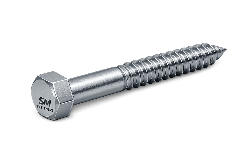
Lag Screw Bolts represent a specialized category of high-load wood and substrate anchoring fasteners designed to transmit structural loads directly into non-metallic base materials without requiring mating nuts or tapped holes.
Unlike standard machine bolts, lag screw bolts generate holding capacity through:
- Threaded substrate engagement
- Radial compression
- Material displacement
- Frictional resistance along embedded thread length
They are extensively specified where:
- One-side access installation is required
- Embedded anchorage replaces through-bolting
- High withdrawal resistance is necessary
- Hybrid assemblies combine steel structures with timber or composite foundations
Typical industrial use environments include:
| Sector | Functional Requirement |
|---|---|
| Structural Steel Construction | Timber-to-steel anchoring |
| Oil & Gas Facilities | Cable trays, sleepers, skid mounts |
| Power Plants | Equipment bases & insulation supports |
| Infrastructure | Guard rails, bridges, sign structures |
| Railways | Timber sleepers and track components |
| Shipbuilding | Deck fixtures and interior structures |
| Heavy Equipment | Crating and transport anchoring |
| Petrochemical Plants | Secondary supports & platforms |
Lag screw bolts remain essential where mechanical anchoring reliability must be achieved without expansion anchors or chemical bonding systems.
1.2 Industrial Procurement Perspective
From an EPC procurement standpoint, lag screw bolts are categorized as:
- Structural anchorage fasteners
- Installation-critical hardware
- Safety-relevant mechanical components
Procurement teams typically evaluate based on:
- Load capacity verification
- Material compatibility
- Corrosion performance
- Traceability documentation
- Dimensional conformity to international standards
SM Fasteners manufactures lag screw bolts under controlled ISO 9001 quality systems, ensuring traceable production suitable for infrastructure and energy projects.
2. Technical Definition
2.1 Engineering Definition
A Lag Screw Bolt is:
A heavy-duty externally threaded fastener with a hex or square head and coarse deep threads designed to be installed directly into wood, engineered timber, polymer composites, or prepared anchor inserts without the use of a nut.
Key distinguishing characteristics:
- Large diameter shank
- Deep coarse thread form
- Partial threading
- High shear cross-section
- Direct torque-driven installation
2.2 Terminology Clarification
| Term | Meaning |
|---|---|
| Lag Screw | Traditional carpentry term |
| Lag Bolt lag bolt | Industry synonym |
| Coach Screw (UK/BS) | Equivalent British terminology |
| Wood Screw Bolt | Trade reference |
| Structural Lag | Engineering usage |
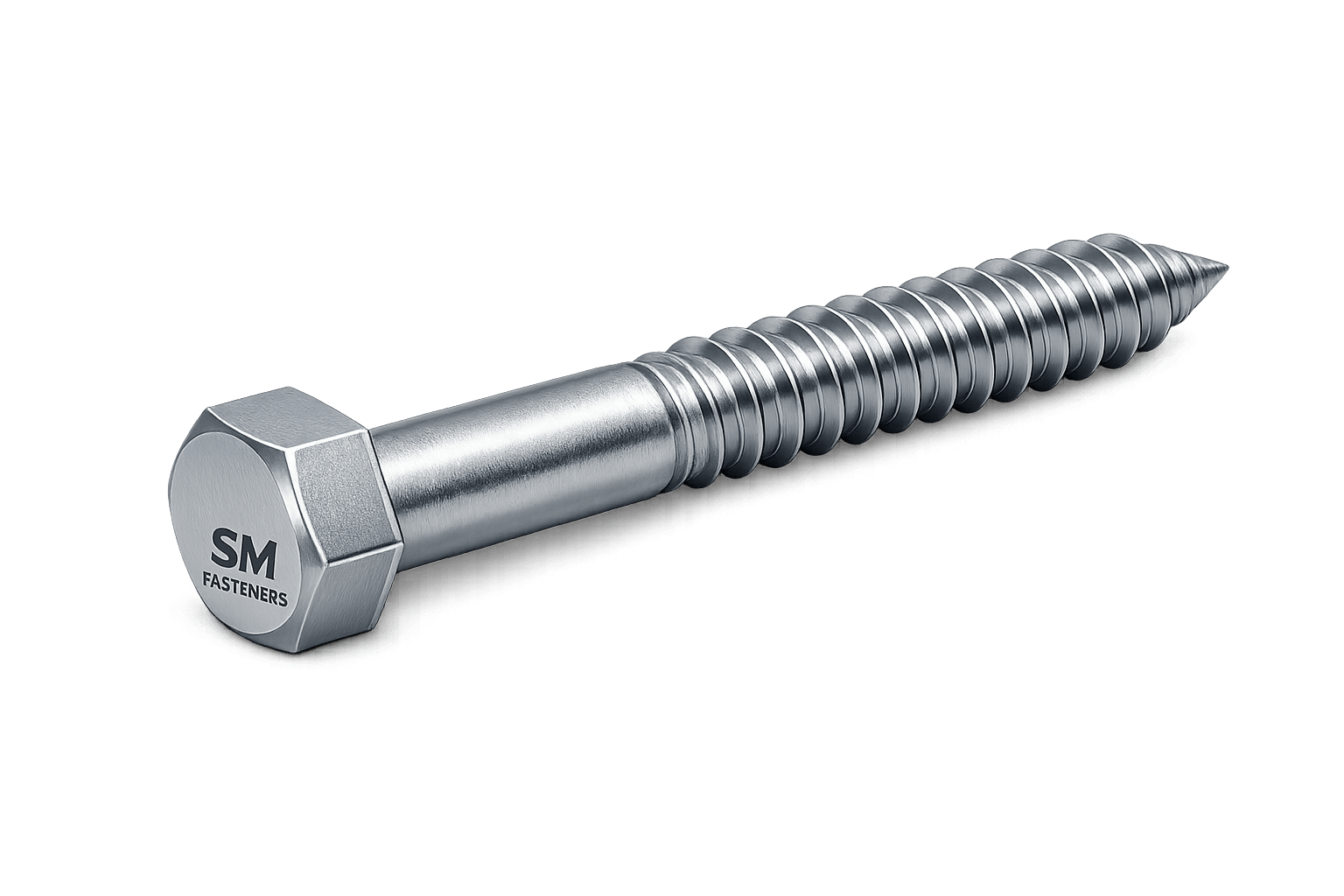
2.3 Primary Components
 ┌────────────┐
 │  HEX HEAD  │
 └─────┬──────┘
       │ Bearing Surface
       │
       │  Smooth Shank
       │
  ======Thread Engagement=====
  Deep Coarse Threads
  Tapered Point
Functional Sections
| Section | Function |
|---|---|
| Head | Torque transmission & clamping |
| Bearing Surface | Load distribution |
| Shank | Shear resistance |
| Thread | Withdrawal resistance |
| Tip | Self-starting penetration |
2.4 Difference from Machine Bolts
| Parameter | Lag Screw Bolt | Machine Bolt |
|---|---|---|
| Nut Required | No | Yes |
| Thread Type | Deep coarse | Standard metric/UN |
| Installation | Driven into substrate | Installed through hole |
| Load Mechanism | Friction + material compression | Clamp force only |
| Primary Application | Wood/composites | Metal joints |
3. Load Mechanics & Force Behavior
Understanding load behavior is critical for structural reliability.
3.1 Load Types Acting on Lag Screw Bolts
Lag screw bolts experience combined stresses:
1. Axial Tensile Load
Force attempting withdrawal from substrate.
Example:
- Suspended equipment
- Cable tray supports
2. Shear Load
Force perpendicular to bolt axis.
Example:
- Structural connections
- Base plates
3. Combined Loading
Most real-world installations involve:
Where:
- = tensile load
- = shear load
3.2 Withdrawal Resistance Mechanics
Holding capacity derives from:
- Thread flank bearing
- Wood fiber compression
- Friction coefficient
- Embedded thread length
Generalized withdrawal formula:
Where:
| Variable | Definition |
|---|---|
| P | Withdrawal load |
| K | Material constant |
| D | Screw diameter |
| L | Thread embedment length |
Engineering Insight
Increasing embedment length is often more effective than increasing diameter beyond optimal ratios.
3.3 Clamping Force Development
Torque applied during installation creates preload:
Where:
- F = Preload force
- T = Applied torque
- K = Nut factor (0.18–0.25 typical)
- D = Nominal diameter
Even without a nut, lag screws generate significant clamping force against joint interfaces.
3.4 Friction Zones Affecting Performance
| Location | Influence |
|---|---|
| Thread/Substrate | Withdrawal capacity |
| Head/Bearing Surface | Clamp force retention |
| Installation Tool | Torque accuracy |
3.5 Load Transfer Mechanism
Lag screw bolts transfer loads through:
- Head compression
- Shank shear resistance
- Thread bearing stresses
- Substrate confinement
Proper joint design ensures load distribution rather than localized crushing.
4. Joint Design Principles
4.1 Engineering Joint Philosophy
Lag screw bolt joints must be designed considering:
- Substrate strength governs capacity
- Fastener strength often exceeds base material strength
- Failure typically occurs in the substrate first
4.2 Recommended Design Parameters
| Parameter | Recommended Practice |
|---|---|
| Pilot Hole | Mandatory for structural installations |
| Edge Distance | ≥ 5 × diameter |
| Spacing | ≥ 8 × diameter |
| Embedment | 6–10 × diameter |
| Washer Use | Required for structural loads |
4.3 Pilot Hole Design
Pilot holes prevent:
- Material splitting
- Torque spikes
- Thread damage
- Installation failure
Typical pilot hole sizing:
| Material | Pilot Hole (% of Root Diameter) |
|---|---|
| Softwood | 60–70% |
| Hardwood | 75–90% |
| Engineered Timber | 70–80% |
| Composite Boards | Engineering verification required |
4.4 Bearing Stress Considerations
Bearing stress beneath the head:
Where:
- = bearing area under head
Washers increase bearing area and prevent embedment failure.
4.5 Failure Modes in Lag Screw Bolt Assemblies
1. Substrate Pull-Out
Most common failure.
Cause:
- Insufficient embedment
- Poor density material
2. Shear Failure of Fastener
Occurs when:
Typically during lateral loading events.
3. Head Pull-Through
Occurs in soft substrates without washer support.
4. Splitting Failure
Caused by inadequate edge distance or oversized fastener.
5. Fatigue Failure
Common in vibration environments:
- rotating machinery bases
- rail systems
- offshore equipment
6. Stress Corrosion Cracking (SCC)
High risk environments:
- Chloride exposure
- Marine atmosphere
- Chemical plants
Material selection becomes critical.
4.6 Design Safety Factors
| Application | Safety Factor |
|---|---|
| Static Structures | 3.0 |
| Dynamic Equipment | 4.0 |
| Offshore Structures | 5.0 |
| Critical Lifting Points | ≥6.0 |
4.7 Engineering Selection Workflow
- Determine service load
- Identify substrate material
- Select diameter based on shear requirement
- Calculate embedment length
- Verify corrosion environment
- Select material grade
- Confirm torque & preload
- Validate inspection documentation
4.8 Role Within Integrated Fastening Systems
Lag screw bolts often function alongside:
- Structural bolts
- Threaded rods
- Anchor bolts
- PEEK fasteners (electrical isolation applications)
SM Fasteners supports engineered assemblies where mixed materials and advanced alloys are required for petrochemical and offshore installations.
5. Product Types and Variants
Lag screw bolts are manufactured in multiple configurations to satisfy structural, mechanical, offshore, and infrastructure applications. Variant selection directly influences installation torque, load transfer efficiency, corrosion resistance, and long-term joint reliability.
5.1 Head Configuration Types
Head geometry governs torque transmission and bearing performance.
| Head Type | Standard Reference | Engineering Function | Typical Application |
|---|---|---|---|
| Hex Head | ASME B18.2.1 | High torque transfer | Structural & heavy equipment |
| Square Head | BS legacy / DIN historical | Anti-rotation | Timber construction |
| Flanged Hex | Manufacturer standard | Increased bearing area | Soft substrates |
| Countersunk Head | DIN 7997 (coach screw equivalent) | Flush installation | Architectural steel |
| Washer Head | Custom | Load distribution | Composite panels |
| Heavy Hex | ASTM adaptation | High preload joints | EPC structures |
Engineering Note:
Hex head lag screw bolts dominate industrial applications due to compatibility with calibrated torque tools.
5.2 Thread Forms and Profiles
Lag screw threads differ fundamentally from machine screw threads.
Primary Thread Characteristics
- Large pitch
- Deep thread height
- Sharp crest penetration
- High flank angle engagement
| Thread Type | Standard | Characteristics | Use Case |
|---|---|---|---|
| Wood Thread | ANSI B18.2.1 adaptation | Deep aggressive profile | Timber anchoring |
| Coach Screw Thread | BSW derived | Traditional UK systems | Infrastructure |
| Unified Coarse (UNC-like) | Modified | Hybrid metal insert systems | Equipment mounting |
| Custom Deep Thread | SM Fasteners | High withdrawal capacity | Offshore crates |
5.3 Point Types
| Point Design | Function |
|---|---|
| Gimlet Point | Self-starting installation |
| Cone Point | Reduced splitting risk |
| Blunt End | Pre-drilled installation |
| Type-17 Cut Point | Chip removal in dense wood |
5.4 Shank Design Variants
| Shank Type | Performance Benefit |
|---|---|
| Partial Thread | Maximized clamping force |
| Full Thread | Increased withdrawal resistance |
| Reduced Shank | Improved fatigue resistance |
| Shoulder Type | Controlled shear plane |
5.5 Drive Interface Compatibility
Industrial installations require repeatable torque application.
| Drive System | Industry Preference |
|---|---|
| Hex Drive | EPC standard |
| Impact Socket Drive | Heavy construction |
| Square Drive | Legacy infrastructure |
| Internal Hex | Limited specialty use |
6. Dimensional Logic and Geometry
Lag screw bolt geometry must balance:
- Shear strength
- Withdrawal resistance
- Installation torque
- Substrate preservation
6.1 Fundamental Geometry Relationships
Critical proportional relationships:
Where:
- = embedment length
- = nominal diameter
Typical Geometric Ratios
| Parameter | Typical Ratio |
|---|---|
| Head Width | 1.5 × Diameter |
| Head Height | 0.6 × Diameter |
| Thread Length | 60–75% of total length |
| Pilot Hole | 70–85% root diameter |
6.2 Standard Dimensional Specification Table
(Representative industrial sizes aligned with SM Fasteners production capability)
| Size | Thread Pitch (Approx) | Length Range (mm) | Head Width (mm) | Head Height (mm) | Recommended Pilot Hole (mm) |
|---|---|---|---|---|---|
| M6 | 2.5 | 25–80 | 10 | 4 | 4.0 |
| M8 | 3.0 | 30–120 | 13 | 5.5 | 5.5 |
| M10 | 3.5 | 40–180 | 17 | 7 | 7.0 |
| M12 | 4.5 | 50–250 | 19 | 8 | 8.5 |
| M16 | 6.0 | 60–300 | 24 | 10 | 11 |
| M20 | 7.0 | 80–350 | 30 | 13 | 14 |
| M24 | 8.0 | 100–400 | 36 | 15 | 17 |
Custom diameters and extended lengths are engineered by SM Fasteners for EPC project requirements.
6.3 Thread Engagement Requirements
Engineering rule:
Higher engagement increases torque demand but improves holding strength.
6.4 Embedment Length Design Table
| Diameter | Minimum Embedment | Structural Embedment | Heavy Load Embedment |
|---|---|---|---|
| M6 | 35 mm | 45 mm | 60 mm |
| M8 | 45 mm | 60 mm | 80 mm |
| M10 | 60 mm | 80 mm | 100 mm |
| M12 | 75 mm | 100 mm | 140 mm |
| M16 | 100 mm | 140 mm | 180 mm |
| M20 | 130 mm | 180 mm | 240 mm |
7. Applicable International Standards
Lag screw bolts operate across multiple legacy and modern standards systems.
7.1 ISO Standards
| Standard | Scope |
|---|---|
| ISO 898-1 | Mechanical properties carbon steel fasteners |
| ISO 965 | Thread tolerances |
| ISO 4759 | Dimensional tolerances |
| ISO 3269 | Acceptance inspection |
| ISO 4042 | Electroplated coatings |
7.2 ASTM Standards
| Standard | Application |
|---|---|
| ASTM A307 | General carbon steel fasteners |
| ASTM A325 (reference) | Structural properties comparison |
| ASTM F593 | Stainless steel fasteners |
| ASTM F594 | Stainless nuts compatibility |
| ASTM B633 | Zinc plating |
| ASTM A153 | Hot-dip galvanizing |
7.3 DIN Standards
| Standard | Description |
|---|---|
| DIN 571 | Hex head wood screws (primary reference) |
| DIN 7997 | Countersunk coach screws |
| DIN 267 | Fastener technical conditions |
| DIN EN ISO 3506 | Stainless fasteners |
DIN 571 remains the most globally recognized lag screw bolt standard.
7.4 British Standards (BS)
| Standard | Application |
|---|---|
| BS 1210 | Coach screws |
| BS 3692 | Metric precision |
| BS EN ISO 4014 | Head geometry reference |
| BSW / BSF | Legacy thread systems |
7.5 Unified Thread Standards
| Thread | Region | Application |
|---|---|---|
| UNC | North America | General construction |
| UNF | Precision assemblies | Machinery mounting |
| BSW | UK/Commonwealth | Infrastructure retrofit |
| Metric Coarse | Global EPC | Standardized projects |
8. Thread Standards & Tolerances Table
| Thread System | Pitch Series | Tolerance Class | Typical Fit |
|---|---|---|---|
| ISO Metric | Coarse | 6g | General industrial |
| ISO Metric | Fine | 6g/6H | Precision assemblies |
| UNC | Coarse | 2A | Construction |
| UNF | Fine | 2A | Machinery |
| BSW | Coarse | Medium Fit | Legacy structures |
| BSF | Fine | Close Fit | Rail & marine |
SM Fasteners manufactures lag screw bolts compliant with multi-standard tolerances to support global interchangeability.
9. Dimensional Tolerances
9.1 Manufacturing Tolerance Control
| Feature | Typical Tolerance |
|---|---|
| Diameter | ±0.1 mm |
| Length | ±1.0 mm |
| Head Width | ±0.2 mm |
| Thread Pitch | ISO class verified |
| Straightness | ≤0.5/100 mm |
Dimensional control is verified under ISO 9001 documented inspection procedures.
10. Mechanical Property Classes (Reference Alignment)
Although lag screw bolts are substrate-governed fasteners, mechanical strength classification remains essential.
| Property Class | Yield Strength (MPa) | Tensile Strength (MPa) | Typical Use |
|---|---|---|---|
| 4.6 | 240 | 400 | Light structural |
| 5.8 | 400 | 500 | General industrial |
| 8.8 | 640 | 800 | Structural mounting |
| 10.9 | 940 | 1040 | Heavy equipment |
| 12.9 | 1100 | 1220 | Specialized engineering |
11. Interchangeability Considerations
Engineering teams must consider:
- Metric vs imperial substitution risks
- Thread penetration differences
- Head dimension conflicts
- Torque requirement variations
Critical projects require dimensional verification prior to substitution.
12. Engineering Selection Logic (Dimensional Perspective)
Selection sequence used by EPC engineering teams:
- Define applied shear load
- Select diameter for shear capacity
- Determine embedment length
- Confirm head bearing capacity
- Verify installation clearance
- Confirm international standard requirement
- Align documentation and inspection class
13. Integration with SM Fasteners Manufacturing Capability
SM Fasteners supports:
- DIN 571 compliant production
- ASTM-compliant materials
- ISO metric and UNC manufacturing
- Custom lengths exceeding standard catalogs
- Special head configurations
- Advanced alloys and PEEK fasteners for electrical isolation or chemical resistance systems
All dimensional outputs align with ISO 9001 certified process controls and project traceability requirements.
14. Material Grades and Selection Criteria
Material selection for lag screw bolts is governed by:
- Load requirements
- Installation environment
- Corrosion exposure
- Temperature range
- Regulatory compliance
- Inspection class requirements
Unlike standard bolts, lag screw bolts interact directly with substrates; therefore material compatibility with surrounding media becomes critical.
14.1 Industrial Material Families
SM Fasteners manufactures lag screw bolts across a full industrial material spectrum.
| Material Family | Common Grades | Primary Characteristics |
|---|---|---|
| Carbon Steel | C1022, EN8, AISI 1018 | High strength, economical |
| Alloy Steel | 4140, 4340 | Heavy structural loads |
| Stainless Steel | 304, 316, 316L | Corrosion resistance |
| Duplex Stainless | 2205 | High strength + corrosion |
| Super Duplex | 2507 | Offshore & seawater |
| Nickel Alloys | Inconel 625, 718 | High temperature |
| Hastelloy | C276 | Acid resistance |
| Monel | 400 | Marine environments |
| SMO 254 | 6Mo alloy | Chloride resistance |
| PEEK | Polymer engineering grade | Electrical insulation |
14.2 Material Selection Decision Matrix
| Environment | Recommended Material |
|---|---|
| Indoor dry | Carbon steel zinc plated |
| Outdoor structural | HDG carbon steel |
| Marine atmosphere | SS316 / Duplex |
| Offshore platform | Super Duplex |
| Chemical plant | Hastelloy / SMO 254 |
| LNG facilities | Low-temperature alloy steel |
| Electrical isolation | PEEK fasteners |
| Sour gas (H₂S) | NACE compliant alloys |
14.3 Material Comparison Table
| Material | UTS (MPa) | Yield (MPa) | Corrosion Resistance | Temperature Limit | Relative Cost | Typical Applications |
|---|---|---|---|---|---|---|
| Carbon Steel | 400–800 | 240–640 | Low | 300°C | Low | Structural |
| Alloy Steel | 900–1200 | 700–1000 | Moderate | 450°C | Medium | Heavy equipment |
| SS304 | 700 | 215 | Good | 425°C | Medium | General industry |
| SS316 | 700 | 220 | Excellent | 425°C | Medium–High | Marine |
| Duplex 2205 | 800 | 550 | Very High | 300°C | High | Offshore |
| Super Duplex 2507 | 950 | 650 | Extreme | 300°C | Very High | Seawater systems |
| Inconel 625 | 900 | 450 | Exceptional | 980°C | Premium | LNG & turbines |
| Hastelloy C276 | 790 | 355 | Acid resistant | 1000°C | Premium | Chemical plants |
| PEEK | 100 | 90 | Chemical inert | 260°C | Specialized | Electrical systems |
15. Mechanical Properties — Grade-Wise
Mechanical performance must comply with ISO 898-1 and ASTM equivalents.
| Property Class | Proof Load (MPa) | Yield Strength (MPa) | Tensile Strength (MPa) | Hardness (HB) |
|---|---|---|---|---|
| 4.6 | 225 | 240 | 400 | 120–180 |
| 5.8 | 380 | 400 | 520 | 150–220 |
| 8.8 | 580 | 640 | 800 | 220–300 |
| 10.9 | 830 | 940 | 1040 | 300–360 |
| 12.9 | 970 | 1100 | 1220 | 360–420 |
15.1 Proof Load & Tensile Capacity Table (Representative)
| Size | Stress Area (mm²) | Proof Load 8.8 (kN) | Tensile 8.8 (kN) | Proof Load 10.9 (kN) |
|---|---|---|---|---|
| M8 | 36.6 | 21 | 29 | 30 |
| M10 | 58 | 34 | 46 | 48 |
| M12 | 84.3 | 49 | 67 | 70 |
| M16 | 157 | 91 | 126 | 130 |
| M20 | 245 | 142 | 196 | 203 |
| M24 | 353 | 205 | 282 | 293 |
Values depend on thread engagement and substrate limitations.
16. Heat Treatment Processes
Heat treatment determines mechanical reliability and fatigue performance.
16.1 Typical Heat Treatment Sequence
- Austenitizing
- Quenching
- Tempering
- Stress relief
- Hardness verification
16.2 Heat Treatment vs Mechanical Effect
| Process | Result |
|---|---|
| Quenching | Increased hardness |
| Tempering | Toughness restoration |
| Normalizing | Grain refinement |
| Annealing | Machinability |
| Solution Annealing | Stainless corrosion resistance |
16.3 Hardness Limits (Critical Engineering Control)
| Service Condition | Maximum Hardness |
|---|---|
| General Service | 32 HRC |
| High Strength | 39 HRC |
| NACE MR0175 Sour Service | ≤22 HRC |
| Hydrogen Risk Areas | Controlled hardness mandatory |
Hardness control prevents hydrogen embrittlement and stress corrosion cracking.
17. End-to-End Manufacturing Workflow
SM Fasteners applies ISO 9001 certified production systems with full traceability.
17.1 Raw Material Verification
Incoming materials verified through:
- Mill Test Certificate (EN 10204 3.1)
- Heat number traceability
- Chemical composition verification
- Positive Material Identification (PMI)
17.2 Forging vs Machining
| Method | Advantage |
|---|---|
| Hot Forging | Grain flow alignment |
| Cold Heading | Dimensional precision |
| CNC Machining | Custom geometry |
| Rolled Shank Production | High fatigue strength |
Forged heads significantly increase impact resistance.
17.3 Thread Production Methods
| Method | Performance |
|---|---|
| Thread Rolling | Superior fatigue life |
| Thread Cutting | Custom sizes |
| Thread Grinding | Precision tolerance |
Thread rolling preferred for structural lag screw bolts.
17.4 Manufacturing Process Flow
Raw Material Inspection
        ↓
Cutting & Preparation
        ↓
Forging / Heading
        ↓
Heat Treatment
        ↓
Thread Rolling
        ↓
Surface Finishing
        ↓
Inspection & Testing
        ↓
Marking & Traceability
        ↓
Packaging
18. Surface Finishing and Coatings
Surface engineering protects lag screw bolts against corrosion, galling, and environmental degradation.
18.1 Coating Types
| Coating | Standard | Typical Thickness | Performance |
|---|---|---|---|
| Zinc Electroplating | ASTM B633 | 5–12 µm | Indoor corrosion |
| Hot Dip Galvanized | ASTM A153 | 50–85 µm | Outdoor structural |
| Mechanical Galvanizing | ASTM B695 | 40–70 µm | Reduced embrittlement |
| Dacromet / Geomet | OEM Spec | 8–12 µm | Automotive |
| PTFE / Xylan | Project Spec | Variable | Low friction |
| Phosphate | DIN | Thin | Assembly aid |
| Passivation | ASTM A967 | — | Stainless protection |
| Nickel Plating | ASTM B689 | Decorative + corrosion |
18.2 Surface Finish Performance Comparison
| Coating | Salt Spray Resistance | Hydrogen Embrittlement Risk | Offshore Suitability |
|---|---|---|---|
| Zinc Plated | 72–120 hrs | Medium | No |
| HDG | 500+ hrs | Low | Yes |
| Mechanical Galv | 400 hrs | Very Low | Yes |
| PTFE | Excellent | None | Chemical plants |
| Stainless Passive | Excellent | None | Marine |
| Duplex Alloy | Extreme | None | Offshore |
18.3 Corrosion Resistance vs Environment
| Environment | Recommended Material/Finish |
|---|---|
| Coastal Atmosphere | HDG / SS316 |
| Seawater Splash Zone | Super Duplex |
| Acid Processing | Hastelloy |
| H₂S Sour Service | NACE compliant alloy |
| Chemical Vapors | PTFE coated |
| High Humidity | Mechanical galvanizing |
| Electrical Panels | PEEK fasteners |
18.4 Hydrogen Embrittlement Control
Critical for high-strength lag screw bolts.
Preventive measures:
- Post-plating baking
- Mechanical galvanizing
- Controlled hardness
- Process validation per ISO 4042
19. Advanced Material Capability — SM Fasteners
SM Fasteners provides engineered solutions including:
- Duplex & Super Duplex lag screw bolts
- Nickel alloy fasteners for LNG and refinery projects
- Custom heat-resistant alloys
- Electrically non-conductive PEEK fasteners for instrumentation and hazardous environments
These materials are integrated into certified manufacturing workflows ensuring EPC project readiness.
19.1 Temperature Capability Overview
| Material | Service Temperature |
|---|---|
| Carbon Steel | −20°C to 300°C |
| Alloy Steel | −40°C to 450°C |
| Stainless Steel | −196°C to 425°C |
| Duplex | −50°C to 300°C |
| Inconel | Up to 980°C |
| PEEK | Up to 260°C |
20. Inspection & Quality Control System
Lag screw bolts used in structural and industrial assemblies must comply with strict inspection regimes to ensure mechanical integrity, dimensional conformity, and long-term reliability.
SM Fasteners integrates inspection activities within an ISO 9001 certified quality management system, enabling traceable compliance for EPC, oil & gas, infrastructure, and heavy engineering projects.
20.1 Incoming Material Inspection
Every production batch begins with controlled raw material verification.
Verification Activities
- Mill Test Certificate (EN 10204 3.1)
- Heat number traceability
- Chemical composition validation
- Positive Material Identification (PMI)
- Visual and dimensional verification
| Inspection Item | Method |
|---|---|
| Chemical Composition | Spectrometer |
| Alloy Confirmation | PMI Analyzer |
| Mechanical Properties | Certificate validation |
| Surface Quality | Visual inspection |
| Heat Traceability | Batch control system |
20.2 In-Process Manufacturing Inspection
| Stage | Inspection Activity |
|---|---|
| Forging | Head dimension check |
| Heat Treatment | Hardness testing |
| Thread Rolling | Go/No-Go gauges |
| Coating | Thickness measurement |
| Marking | Traceability verification |
20.3 Final Inspection Requirements
Final inspection ensures product release suitability.
Mechanical Testing
- Tensile testing
- Proof load testing
- Hardness testing
- Bend testing (where applicable)
Dimensional Inspection
- Head dimensions
- Thread pitch
- Overall length
- Straightness
- Thread engagement length
20.4 Non-Destructive Testing (NDT)
Used for critical industrial orders.
| NDT Method | Purpose |
|---|---|
| Magnetic Particle Testing | Crack detection |
| Dye Penetrant Inspection | Surface flaws |
| Ultrasonic Testing | Internal defects |
| Eddy Current Testing | Material discontinuity |
20.5 Certification & Documentation
Typical documentation supplied:
- EN 10204 3.1 / 3.2 MTC
- Heat treatment reports
- Coating certificates
- Inspection reports
- Dimensional reports
- Compliance Certificate (CoC)
21. Mechanical Properties Table (Engineering Reference)
| Grade | Yield Strength (MPa) | Tensile Strength (MPa) | Proof Stress (MPa) | Elongation (%) |
|---|---|---|---|---|
| 4.6 | 240 | 400 | 225 | 22 |
| 5.8 | 400 | 520 | 380 | 14 |
| 8.8 | 640 | 800 | 580 | 12 |
| 10.9 | 940 | 1040 | 830 | 9 |
| 12.9 | 1100 | 1220 | 970 | 8 |
22. Tightening Torque Chart
Torque values vary with lubrication and coating friction.
| Size | Grade | Dry Torque (Nm) | Lubricated Torque (Nm) | HDG Torque (Nm) |
|---|---|---|---|---|
| M8 | 8.8 | 25 | 18 | 20 |
| M10 | 8.8 | 50 | 35 | 40 |
| M12 | 8.8 | 85 | 60 | 70 |
| M16 | 8.8 | 210 | 150 | 170 |
| M20 | 8.8 | 410 | 290 | 330 |
| M24 | 8.8 | 710 | 500 | 560 |
Engineering Note:
Lag screw bolts rely partially on substrate friction; torque verification should consider pilot hole quality.
23. Preload Calculation
Preload ensures joint stability and vibration resistance.
Formula
Where:
- F = preload force
- T = torque
- K = nut factor (0.20 typical)
- D = nominal diameter
Worked Example
Bolt: M12 Lag Screw Bolt
Torque Applied: 85 Nm
Diameter: 12 mm (0.012 m)
Result:
Approximate preload ≈ 35 kN
24. Failure Mechanisms & Prevention
| Failure Mode | Cause | Prevention |
|---|---|---|
| Pull-Out | Insufficient embedment | Increase engagement |
| Shear Failure | Undersized diameter | Upgrade size/grade |
| Fatigue | Dynamic loads | Proper preload |
| Hydrogen Embrittlement | Improper plating | Controlled coating |
| SCC | Chloride exposure | Material upgrade |
| Head Crushing | No washer | Use hardened washer |
25. Weight Chart — Lag Screw Bolts
(Representative values aligned with SM Fasteners manufacturing data)
| Size | Length | Weight/Piece (kg) | Weight/100 pcs (kg) |
|---|---|---|---|
| M8×60 | 0.018 | 1.8 | |
| M10×80 | 0.035 | 3.5 | |
| M12×100 | 0.065 | 6.5 | |
| M16×120 | 0.130 | 13 | |
| M20×150 | 0.240 | 24 | |
| M24×200 | 0.480 | 48 |
Used for:
- EPC BOQ preparation
- Freight calculations
- Container optimization
26. Surface Finish Performance Table
| Surface Finish | Corrosion Protection | Friction Control | Typical Industry |
|---|---|---|---|
| Zinc Plated | Moderate | Good | Indoor installations |
| HDG | High | Moderate | Structural construction |
| PTFE | Excellent | Excellent | Chemical plants |
| Passivated Stainless | Excellent | Good | Marine |
| Mechanical Galv | High | Good | Infrastructure |
| Duplex Alloy | Extreme | Excellent | Offshore |
27. Corrosion Resistance vs Environment
| Environment | Recommended Solution |
|---|---|
| Seawater | Super Duplex / SS316 |
| Acidic Process | Hastelloy |
| H₂S Service | NACE MR0175 compliant |
| Coastal | HDG Carbon Steel |
| LNG Cryogenic | Stainless Steel |
| Electrical Isolation | PEEK fasteners |
28. Industry Applications
28.1 Construction & Structural Steel
- Timber-to-steel connections
- Guard rails
- Bridge structures
- Formwork anchoring
28.2 Oil & Gas Industry
Upstream
- Skid structures
- Pipe supports
- Temporary drilling platforms
Midstream
- Compressor bases
- Cable routing supports
Downstream
- Refinery maintenance structures
- Equipment insulation frames
Materials frequently comply with NACE MR0175 / ISO 15156.
28.3 Power Generation
- Turbine housing supports
- Cable trays
- Transformer mounting structures
- Renewable energy foundations
28.4 Petrochemical & Chemical Processing
- Corrosion-resistant assemblies
- Chemical tank platforms
- Maintenance walkways
28.5 LNG & Offshore Installations
- Marine deck structures
- Offshore living quarters
- Splash-zone anchoring systems
Duplex and nickel alloy lag screw bolts are preferred.
28.6 Railways & Infrastructure
- Timber sleepers
- Signage structures
- Noise barriers
- Track accessories
28.7 Shipbuilding & Marine Engineering
- Interior fastening systems
- Deck hardware anchoring
- Insulated structures
28.8 Automotive & Heavy Equipment
- Transport crating
- Equipment mounting bases
- Structural panels
28.9 PEEK Fastener Applications
SM Fasteners supplies engineered PEEK lag-type fastening solutions for:
- Electrical isolation
- Non-magnetic assemblies
- Chemical instrumentation
- Semiconductor environments
29. Export Capability & Industrial Packaging
29.1 Industrial Packaging Methods
| Method | Purpose |
|---|---|
| VCI Packaging | Corrosion prevention |
| Thread Protectors | Prevent damage |
| Polybag + Carton | Controlled handling |
| Heavy Pallet Packing | Bulk shipment |
| Moisture Barrier Bags | Marine export |
29.2 Export Crating
- ISPM-15 compliant wooden crates
- Container load optimization
- Batch traceability labeling
- Shock-resistant packaging
29.3 Documentation Package
Supplied with international shipments:
- Mill Test Certificate (3.1 / 3.2)
- Inspection Release Note
- Packing List
- Certificate of Conformity
- Heat Treatment Reports
- Coating Certification
- Third-Party Inspection (TPI) Reports
30. Thread Standards & Tolerances Summary
| Standard | Thread | Typical Tolerance |
|---|---|---|
| ISO Metric | M Series | 6g |
| UNC | Unified Coarse | 2A |
| UNF | Unified Fine | 2A |
| BSW | British Standard Whitworth | Medium Fit |
| BSF | British Standard Fine | Close Fit |
31. Engineering Procurement Checklist
Used by EPC buyers and QA engineers.
✔ Verify applicable standard
✔ Confirm material grade
✔ Check coating requirement
✔ Validate preload requirement
✔ Review inspection class
✔ Confirm documentation package
✔ Validate weight data for logistics
✔ Confirm traceability compliance
32. SM Fasteners — Engineering Manufacturing Capability
Through ISO 9001 certified systems and UKAF-accredited quality practices, SM Fasteners provides:
- Precision forged lag screw bolts
- Multi-standard manufacturing (ISO / ASTM / DIN / BS)
- Advanced alloy manufacturing capability
- Custom engineered fasteners
- Full inspection traceability
- EPC project documentation readiness
- Global export supply capability
The manufacturing and quality framework ensures lag screw bolts meet demanding requirements across energy, infrastructure, offshore, petrochemical, and heavy engineering sectors.