

Speed Nut
1. Industry Context
Speed Nuts are specialized self-retaining sheet fastening elements developed to support high-volume industrial assembly, thin-section joining, and blind installation environments where conventional nut-and-bolt assemblies are impractical.
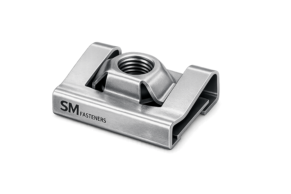
Within modern engineering sectors, speed nuts serve a critical function in:
- Automotive body systems
- HVAC assemblies
- Electrical enclosures
- Sheet metal fabrication
- Rail coach manufacturing
- Heavy equipment panels
- Infrastructure assemblies
- Industrial equipment guarding systems
Unlike traditional hex nuts requiring backside access and torque tools, speed nuts enable:
- Single-sided installation
- Rapid assembly cycles
- Reduced labor dependency
- Consistent preload generation
- Weight reduction in assemblies
For EPC contractors and OEM manufacturers, speed nuts significantly reduce Total Installed Cost (TIC) while maintaining mechanical reliability.
SM Fasteners manufactures precision-engineered Speed Nuts aligned with global industrial quality systems, supporting high-volume automated assembly lines and export-driven supply chains.
2. Technical Definition
A Speed Nut is a spring steel or formed metal fastener designed to:
- Clip onto sheet material or structural edges
- Provide a captive threaded interface
- Generate locking action through elastic deformation
Functional Characteristics
| Characteristic | Engineering Function |
|---|---|
| Spring action | Maintains continuous thread pressure |
| Self-retention | Eliminates loose hardware |
| Floating tolerance | Compensates hole misalignment |
| Sheet metal compatibility | Suitable for thin substrates |
| Anti-vibration | Maintains preload under dynamic loads |
Speed nuts typically function with:
- Machine screws
- Self-tapping screws
- Thread forming screws
- Metric or Unified fasteners
3. Load Mechanics & Force Behavior
Speed nut performance depends on elastic energy storage within the formed metal geometry.
Primary Load Modes
3.1 Clamp Load (Primary Load)
Generated when screw torque produces axial tension:
Where:
- = Preload force (N)
- = Applied torque (Nm)
- = Nut factor (0.18–0.25 typical)
- = Nominal diameter (m)
3.2 Spring Retention Force
The speed nut arms act as cantilever springs:
- Provide continuous contact pressure
- Prevent loosening
- Maintain vibration resistance
3.3 Load Transfer Path
Load distribution sequence:
- Screw head → panel surface
- Panel → speed nut contact zone
- Thread engagement → spring arms
- Elastic deformation → preload stabilization
3.4 Shear Resistance
Unlike structural nuts, speed nuts are not primary shear-load fasteners.
Engineering practice:
- Shear loads carried by panel interface
- Speed nut provides clamping retention only
3.5 Vibration Performance
Locking is achieved through:
- Radial thread interference
- Spring compression
- Frictional damping
Suitable for:
- Automotive vibration spectra
- Railway oscillation environments
- Industrial rotating equipment panels
4. Joint Design Principles
Proper joint design ensures performance reliability.
4.1 Substrate Compatibility
| Substrate Type | Recommended |
|---|---|
| Sheet metal | Excellent |
| Aluminum panels | Excellent |
| Composite panels | Good |
| Thick structural members | Not recommended |
Typical thickness range:
0.5 mm – 6 mm
4.2 Edge Distance Requirements
Minimum edge distance:
Prevents deformation and loss of retention.
4.3 Thread Engagement
Recommended engagement:
| Thread Size | Minimum Engagement |
|---|---|
| M4 | 4 mm |
| M5 | 5 mm |
| M6 | 6 mm |
| M8 | 8 mm |
4.4 Torque–Tension Relationship
Critical influencing parameters:
- Surface finish
- Coating friction coefficient
- Lubrication condition
- Thread class tolerance
Speed nuts rely on controlled friction, therefore over-lubrication must be avoided unless torque recalibration is applied.
4.5 Failure Mechanisms
A. Thread Stripping
Occurs when:
- Panel too thin
- Material hardness mismatch
B. Spring Fatigue
Caused by repeated removal cycles.
Recommended reuse limit:
3–5 installation cycles (typical industrial practice).
C. Over-Torque Collapse
Excess torque plastically deforms nut arms.
D. Corrosion-Induced Seizure
Common in outdoor or marine environments without coatings.
4.6 Design Advantages for EPC Projects
- No secondary access required
- Faster installation
- Reduced assembly tools
- Lower inventory complexity
- Improved maintainability
4.7 Engineering Selection Criteria
| Parameter | Selection Basis |
|---|---|
| Load | Light–medium clamp loads |
| Environment | Indoor / coated outdoor |
| Assembly speed | High-volume lines |
| Accessibility | Blind installation |
| Maintenance | Quick removal |
4.8 Comparison vs Conventional Nut Systems
| Feature | Speed Nut | Hex Nut |
|---|---|---|
| Installation side | Single | Dual |
| Assembly speed | Very high | Moderate |
| Structural load | Limited | High |
| Automation compatibility | Excellent | Moderate |
| Weight | Low | Higher |
4.9 Functional Role in Modern Engineering Assemblies
Speed nuts act as:
- Retained thread providers
- Panel fastening solutions
- Assembly acceleration components
Common integration:
- Equipment covers
- Cable trays
- Vehicle interiors
- Electrical cabinets
- HVAC ducts
4.10 SM Fasteners Engineering Integration
SM Fasteners manufactures speed nuts under:
- ISO 9001 controlled processes
- Traceable raw materials
- Global dimensional compliance
- Custom geometry engineering
- Advanced alloy and corrosion-resistant materials
Capabilities include:
- Stainless & alloy grades
- High-spring carbon steel
- Duplex & Nickel alloys
- PEEK engineered fasteners for electrical insulation applications
5. Product Types and Variants
Speed Nuts are engineered in multiple geometries to accommodate different assembly access conditions, panel designs, and thread engagement requirements. Selection depends on installation direction, panel thickness, vibration exposure, and service environment.
SM Fasteners manufactures standardized and custom-engineered speed nuts suitable for OEM, EPC, and export industrial applications.
5.1 U-Type speed nut (U-Clip Nut)
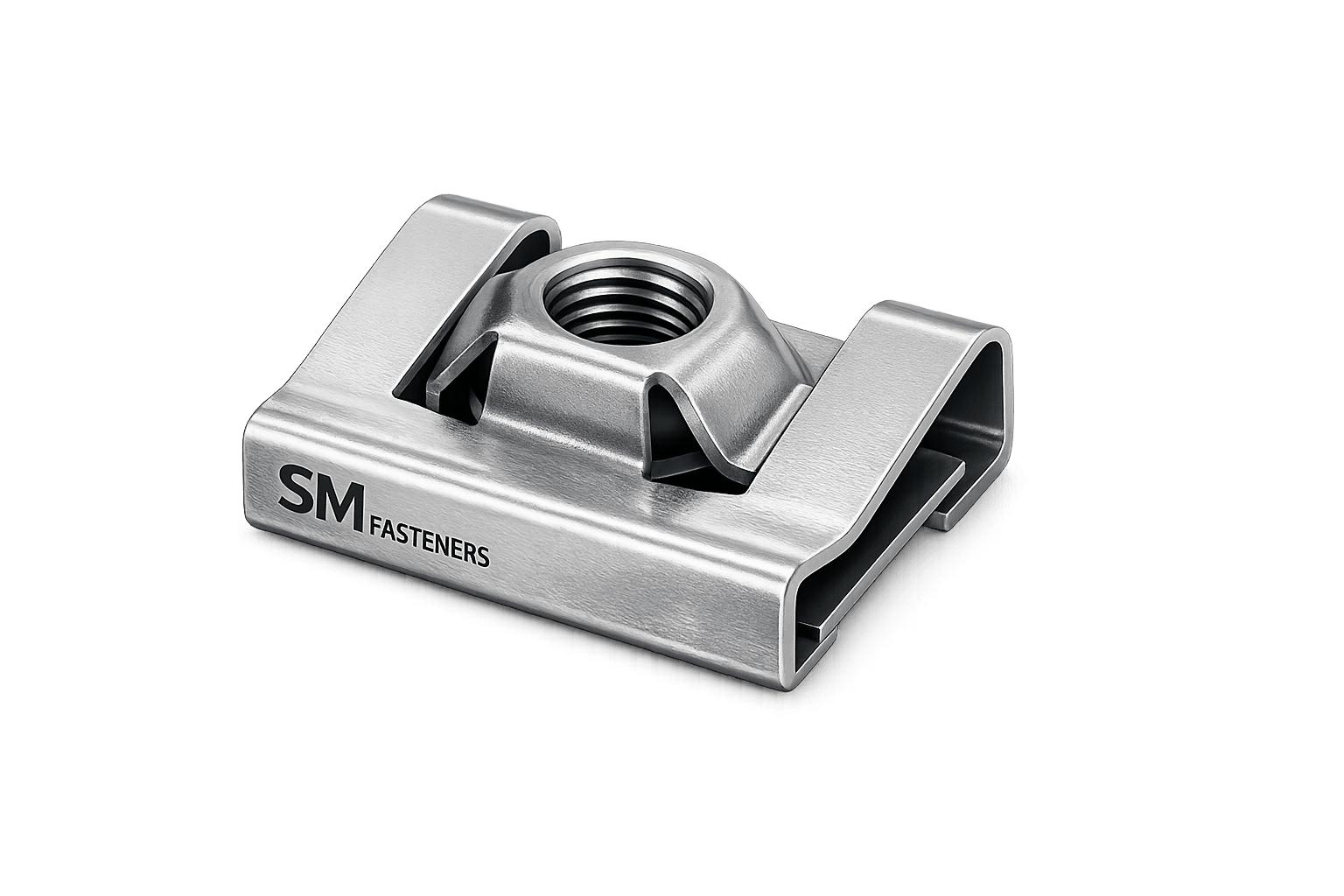
Most widely used industrial configuration.
Design Principle
- U-shaped spring steel clip
- Slides over sheet edge
- Captive floating threaded feature
Engineering Characteristics
| Parameter | Description |
|---|---|
| Installation | Edge clip |
| Alignment tolerance | High |
| Assembly speed | Excellent |
| Serviceability | Reusable |
| Typical industries | Automotive, HVAC, Electrical Panels |
Advantages:
- No pre-threaded hole required
- Accommodates panel tolerance variation
- Enables blind assembly
5.2 J-Type Speed Nut
Used where panel access is restricted to one side only.
Characteristics
- Single-leg retention design
- Compact footprint
- Reduced material usage
Applications:
- Appliance assemblies
- Light enclosures
- Interior panel fixing
5.3 Flat Speed Nut (Push-On Type)
Threadless locking design relying on radial gripping force.
| Feature | Engineering Function |
|---|---|
| Serrated bore | Shaft retention |
| No threads | Fast push installation |
| High vibration resistance | Mechanical grip locking |
Used for:
- Stud retention
- Shaft locking
- Electrical insulation supports
5.4 Panel Speed Nut (Extruded Thread Type)
Manufactured with formed internal threads.
Engineering benefits:
- Improved load distribution
- Higher pull-out resistance
- Increased thread engagement depth
5.5 Floating Speed Nut
Allows controlled lateral movement.
Purpose:
- Compensates hole misalignment
- Enables robotic assembly tolerance
Common in:
- Automotive body-in-white
- Aerospace interiors
- Rail coach fabrication
5.6 Self-Locking Speed Nut
Incorporates locking deformation.
Locking achieved by:
- Elliptical thread section
- Spring pressure interference
Provides resistance against:
- Vibration loosening
- Thermal cycling
5.7 Heavy-Duty Speed Nut
Designed for industrial equipment panels.
Features:
- Thick gauge material
- Increased spring stiffness
- Higher torque capacity
Used in:
- Construction equipment
- Power generation housings
- Offshore modules
5.8 PEEK Speed Nuts (Special Engineering Variant)
SM Fasteners supplies PEEK polymer speed nuts for extreme environments.
Advantages:
| Property | Benefit |
|---|---|
| Electrical insulation | Electronics & rail |
| Chemical resistance | Process plants |
| Lightweight | Aerospace & instrumentation |
| Non-magnetic | Sensitive equipment |
Temperature capability:
−70°C to +260°C
6. Dimensional Logic and Geometry
Speed nut geometry directly governs mechanical performance.
6.1 Critical Geometric Parameters
| Parameter | Symbol | Function |
|---|---|---|
| Nominal screw diameter | D | Load capacity |
| Clip opening width | W | Panel compatibility |
| Material thickness | t | Spring force |
| Thread engagement height | H | Clamp reliability |
| Grip range | G | Panel thickness tolerance |
6.2 Engineering Geometry Principles
Spring Deflection Design
Speed nuts operate within elastic limits:σ=bt26FL
Where:
- F = Applied force
- L = Arm length
- b = Width
- t = Thickness
Proper design ensures:
- Elastic recovery
- Long fatigue life
- Consistent retention force
6.3 Standard Dimensional Specification Table
(Representative SM Fasteners Engineering Data)
| Thread Size | Screw Dia (mm) | Clip Width (mm) | Material Thickness (mm) | Grip Range (mm) | Hole Size (mm) |
|---|---|---|---|---|---|
| M3 | 3 | 8 | 0.5–0.6 | 0.5–2 | 3.2 |
| M4 | 4 | 9 | 0.6–0.8 | 0.6–3 | 4.2 |
| M5 | 5 | 11 | 0.7–0.9 | 0.8–4 | 5.2 |
| M6 | 6 | 13 | 0.8–1.0 | 1–5 | 6.3 |
| M8 | 8 | 17 | 1.0–1.2 | 1–6 | 8.4 |
| M10 | 10 | 21 | 1.2–1.6 | 2–8 | 10.5 |
6.4 Weight Chart (SM Fasteners Reference)
| Size | Weight / Piece (g) | Weight / 100 pcs (kg) |
|---|---|---|
| M3 | 0.7 | 0.07 |
| M4 | 1.2 | 0.12 |
| M5 | 2.0 | 0.20 |
| M6 | 3.2 | 0.32 |
| M8 | 6.0 | 0.60 |
| M10 | 9.5 | 0.95 |
Weight control supports EPC logistics planning and export documentation.
7. Thread Standards & Compatibility
Speed nuts must match international thread systems used in global equipment.
7.1 Metric Threads — ISO System
Applicable Standards:
- ISO 261 — Metric thread series
- ISO 965 — Tolerances
- ISO 68-1 — Basic profile
Common tolerance class:
6H internal thread
7.2 Unified Thread System
| Thread Type | Standard |
|---|---|
| UNC | ASME B1.1 |
| UNF | ASME B1.1 |
| UNEF | Aerospace applications |
Used primarily for US-origin equipment.
7.3 British Thread Standards
| Standard | Application |
|---|---|
| BSW | Legacy infrastructure |
| BSF | Fine-thread machinery |
| BS 3643 | Metric adoption |
7.4 Thread Tolerance Table
| Thread System | Internal Class | External Class | Fit Type |
|---|---|---|---|
| Metric | 6H | 6g | General |
| UNC | 2B | 2A | Industrial |
| UNF | 2B | 2A | Precision |
| BSW | Medium | Medium | Legacy |
8. Applicable International Standards
Speed nuts are governed by dimensional, material, and mechanical references rather than one single universal specification.
8.1 DIN Standards
| Standard | Scope |
|---|---|
| DIN 6799 | Retaining fasteners |
| DIN 7965 | Sheet metal fasteners |
| DIN EN ISO 4759 | Fastener tolerances |
8.2 ISO Standards
| Standard | Coverage |
|---|---|
| ISO 898 | Mechanical properties |
| ISO 4042 | Electroplating |
| ISO 10683 | Zinc flake coatings |
| ISO 3506 | Stainless steel fasteners |
8.3 ASTM Standards
| Standard | Application |
|---|---|
| ASTM A1008 | Sheet steel |
| ASTM A684 | Spring steel |
| ASTM F1941 | Coating systems |
| ASTM B633 | Zinc plating |
8.4 British Standards (BS)
| Standard | Coverage |
|---|---|
| BS 4183 | Metric fasteners |
| BS EN 10204 | Certification |
| BS 3692 | Threaded fasteners |
9. Interchangeability & Global Procurement Logic
EPC procurement frequently requires cross-standard compatibility.
Key considerations:
- Metric ↔ Unified conversion
- Coating thickness tolerance effects
- Thread class matching
- Panel thickness variation
SM Fasteners engineering teams provide:
- Drawing validation
- Reverse engineering
- Global equivalency mapping
- Custom tolerance design
10. Engineering Selection Matrix
| Requirement | Recommended Variant |
|---|---|
| High vibration | Self-locking speed nut |
| Misaligned holes | Floating speed nut |
| Electrical isolation | PEEK speed nut |
| Outdoor environment | Stainless steel |
| High-volume assembly | U-type speed nut |
| Heavy equipment | Heavy-duty variant |
11. Design Integration with Automated Assembly
Speed nuts are optimized for:
- Robotic screwdrivers
- Conveyor assembly lines
- Pre-installed panel systems
- Modular fabrication
Benefits:
- Reduced takt time
- Controlled torque repeatability
- Lower operator dependency
12. SM Fasteners Manufacturing Capability Alignment
SM Fasteners supports global buyers through:
- ISO 9001 process control
- UKAF-certified quality management
- MSME manufacturing scale flexibility
- Custom geometry development
- Multi-material production including nickel alloys and PEEK
Engineering deliverables include:
- 2D/3D CAD validation
- PPAP documentation (when required)
- Batch traceability
- Export-ready packaging standards
13. Material Grades and Selection Criteria
Speed Nuts function fundamentally as spring-loaded fastening devices, therefore material selection is governed by:
- Elastic recovery capability
- Fatigue resistance
- Surface hardness
- Corrosion performance
- Formability during stamping
- Long-term stress relaxation resistance
Unlike conventional nuts designed primarily for tensile strength, speed nuts require an optimized balance between strength and controlled flexibility.
SM Fasteners manufactures speed nuts across a wide industrial material spectrum compliant with global standards and EPC procurement requirements.
13.1 Primary Material Categories
| Material Group | Typical Standards | Core Purpose |
|---|---|---|
| Spring Carbon Steel | ASTM A684 / EN 10132 | High elasticity |
| Stainless Steel | AISI 304 / 316 / ISO 3506 | Corrosion resistance |
| Alloy Steel | ASTM A574 / EN 10083 | Higher strength |
| Duplex Stainless Steel | UNS S31803 | Marine & offshore |
| Nickel Alloys | Inconel, Monel, Hastelloy | Extreme environments |
| Engineering Polymer (PEEK) | ASTM D6262 | Electrical isolation |
13.2 Carbon Spring Steel (Most Common)
Typical grades:
- SAE 1074
- SAE 1075
- C75S
- EN 10270 spring steel
Engineering Advantages
- Excellent elastic recovery
- High fatigue resistance
- Cost efficiency
- Ideal for high-volume automotive assemblies
Hardness after treatment:
HRC 40–50
13.3 Stainless Steel Speed Nuts
AISI 304 (1.4301)
- General industrial environments
- Indoor equipment
- Moderate corrosion exposure
AISI 316 / 316L (1.4401 / 1.4404)
- Marine atmosphere
- Chemical processing
- Offshore installations
13.4 Duplex & Super Duplex Stainless Steel
Used where both strength and corrosion resistance are critical.
| Grade | Standard | Application |
|---|---|---|
| Duplex 2205 | UNS S31803 | Offshore |
| Super Duplex 2507 | UNS S32750 | Seawater systems |
Advantages:
- High chloride resistance
- Stress corrosion resistance
- High yield strength
13.5 Nickel-Based Alloys
Available through SM Fasteners custom programs.
| Alloy | Key Property |
|---|---|
| Inconel 625 | High temperature strength |
| Hastelloy C276 | Acid resistance |
| Monel 400 | Seawater corrosion resistance |
| Incoloy 825 | Chemical stability |
Used in:
- LNG plants
- Refineries
- Chemical reactors
13.6 PEEK Speed Nuts (Advanced Engineering Solution)
PEEK provides non-metallic fastening solutions.
| Property | Value |
|---|---|
| Continuous temperature | 260°C |
| Dielectric strength | Excellent |
| Chemical resistance | Outstanding |
| Weight reduction | ~70% lighter than steel |
Applications:
- Electrical equipment
- Semiconductor systems
- Rail signaling
- MRI-compatible assemblies
14. Material Comparison Table
| Material | UTS (MPa) | Yield Strength (MPa) | Corrosion Resistance | Temp Limit | Cost Level | Typical Application |
|---|---|---|---|---|---|---|
| Carbon Spring Steel | 900–1200 | 700 | Low | 150°C | Low | Automotive |
| SS 304 | 515–620 | 205 | Good | 400°C | Medium | General industry |
| SS 316 | 515–620 | 205 | Excellent | 450°C | Medium-High | Marine |
| Duplex 2205 | 620–880 | 450 | Very High | 300°C | High | Offshore |
| Inconel 625 | 827 | 414 | Exceptional | 700°C | Very High | LNG |
| PEEK | 100 | 90 | Chemical resistant | 260°C | High | Electronics |
15. Corrosion Resistance vs Environment
| Environment | Carbon Steel | SS304 | SS316 | Duplex | Nickel Alloy | PEEK |
|---|---|---|---|---|---|---|
| Indoor Industrial | Good | Excellent | Excellent | Excellent | Excellent | Excellent |
| Outdoor Atmosphere | Fair | Good | Excellent | Excellent | Excellent | Excellent |
| Marine Seawater | Poor | Moderate | Excellent | Superior | Superior | Excellent |
| Acidic Chemical | Poor | Moderate | Good | Very Good | Outstanding | Outstanding |
| H₂S Sour Service | Not Recommended | Limited | Good | Excellent | Excellent | Excellent |
Duplex and nickel alloys can be supplied compliant with:
NACE MR0175 / ISO 15156 (sour gas environments).
16. Mechanical Properties (Grade-Wise)
Although speed nuts are not classified like bolt property classes, mechanical performance is still controlled.
| Material | Hardness | Spring Modulus | Fatigue Resistance |
|---|---|---|---|
| Spring Steel | HRC 40–50 | High | Excellent |
| Stainless Steel | HRB 85–95 | Medium | Good |
| Duplex Steel | HRC 28–32 | High | Excellent |
| Nickel Alloys | HRC 20–35 | Medium | Excellent |
| PEEK | Shore D 85 | Low | Excellent |
17. Heat Treatment Processes
Heat treatment determines spring functionality.
17.1 Austenitizing
Steel heated to:
800–870°C
Purpose:
- Dissolve carbides
- Prepare martensitic structure
17.2 Quenching
Rapid cooling:
- Oil quench
- Polymer quench
Produces high hardness required for spring action.
17.3 Tempering
Critical step controlling elasticity.
Typical range:
350–500°C
Outcome:
- Reduced brittleness
- Improved fatigue life
- Stable spring recovery
17.4 Stress Relieving
Applied after forming.
Prevents:
- Shape distortion
- Long-term relaxation
17.5 Solution Annealing (Stainless Steel)
Temperature:
1040–1120°C
Ensures:
- Corrosion resistance restoration
- Removal of work hardening
17.6 Hydrogen Embrittlement Prevention
Mandatory for plated high-strength steels.
SM Fasteners controls risk through:
- Post-plate baking (200°C / 4 hrs)
- Controlled electroplating parameters
- Hardness monitoring
18. End-to-End Manufacturing Workflow
SM Fasteners applies ISO 9001 certified manufacturing control from raw material to shipment.
18.1 Raw Material Verification
Incoming inspection includes:
- Mill Test Certificate (EN 10204 3.1)
- Chemical composition verification
- Mechanical property validation
- PMI testing for alloy grades
18.2 Coil Preparation
Steel supplied in coils:
- Thickness tolerance verification
- Surface inspection
- Lubrication application
18.3 Progressive Die Stamping
High-speed stamping produces geometry.
Advantages:
- Dimensional repeatability
- High productivity
- Reduced material waste
Tooling accuracy:
±0.02 mm typical.
18.4 Piercing and Forming Operations
Processes include:
- Hole piercing
- Thread-forming deformation
- Clip shaping
- Spring arm creation
18.5 Thread Formation
Two methods:
| Method | Benefit |
|---|---|
| Thread rolling | Higher strength |
| Thread forming | Faster production |
Cut threads avoided where possible to preserve grain flow.
18.6 Heat Treatment
Performed in controlled furnaces:
- Continuous belt furnace
- Protective atmosphere
- Hardness validation
18.7 Surface Preparation
Pre-treatment steps:
- Degreasing
- Pickling
- Shot blasting
- Passivation
18.8 Surface Coating Application
(Details expanded below.)
18.9 Final Calibration & Sorting
- Spring force verification
- Thread gauge testing
- Vision inspection systems
18.10 Traceability System
Each batch linked to:
- Heat number
- Production lot
- Inspection records
- Operator traceability
Aligned with ISO 9001 quality management.
19. Surface Finishing and Protective Coatings
Surface engineering directly influences durability and torque characteristics.
19.1 Surface Finish Comparison Table
| Coating | Standard | Corrosion Resistance | Friction Control | Typical Use |
|---|---|---|---|---|
| Zinc Plating | ASTM B633 | 72–120 hrs | Good | Indoor |
| Zinc Yellow | ASTM B633 Type II | Improved | Good | Automotive |
| Zinc-Nickel | ASTM F1941 | 500–1000 hrs | Excellent | OEM |
| Mechanical Galvanizing | ASTM B695 | High | Moderate | Structural |
| Hot Dip Galvanized | ISO 1461 | Very High | High friction | Outdoor |
| Dacromet / Geomet | ISO 10683 | Excellent | Controlled | Automotive |
| Phosphate + Oil | MIL-DTL-16232 | Moderate | Excellent | Assembly lines |
| Passivation (SS) | ASTM A967 | Corrosion resistance | Neutral | Stainless |
| PTFE Topcoat | ISO 16047 | Low friction | Excellent | Controlled torque |
19.2 Coating Selection vs Environment
| Environment | Recommended Coating |
|---|---|
| Indoor industrial | Zinc plated |
| Automotive | Zinc-nickel / Geomet |
| Offshore | SS316 / Duplex |
| Chemical plant | Nickel alloy / passivated |
| Electrical insulation | PEEK |
19.3 Coating Thickness Control
Typical ranges:
- Electroplating: 5–12 µm
- Zinc flake: 8–15 µm
- HDG: 45–85 µm
Controlled thickness prevents thread interference.
19.5 SM Fasteners Surface Engineering Capability
SM Fasteners provides:
- RoHS compliant coatings
- REACH compliant processes
- Controlled friction coatings
- Custom corrosion protection programs
- Project-specific coating validation
All finishes supported with traceable inspection documentation.
20. Inspection & Quality Control System
Speed Nuts operate as functional spring fasteners, therefore inspection must verify not only dimensions but also elastic performance, thread integrity, and coating durability.
SM Fasteners integrates inspection activities into an ISO 9001 certified quality management system, ensuring traceability from raw material to international shipment.
20.1 Incoming Material Inspection
All production begins with controlled raw material validation.
Verification Activities
- Mill Test Certificate review (EN 10204 3.1)
- Chemical composition confirmation
- Mechanical property validation
- Coil thickness tolerance inspection
- Surface defect inspection
- Positive Material Identification (PMI) for alloy grades
Applicable Standards:
- ASTM A751 — Chemical analysis
- ISO 6892 — Tensile testing
- ASTM E415 — Spectrometry
20.2 In-Process Dimensional Inspection
Critical inspection stages include:
| Process Stage | Inspection Method |
|---|---|
| Stamping | Optical measurement |
| Forming | Go/No-Go gauges |
| Thread forming | Thread plug gauges |
| Heat treatment | Hardness testing |
| Coating | Thickness measurement |
Typical tolerance capability:
±0.02–0.05 mm
20.3 Mechanical Testing
Because speed nuts rely on spring action, functional testing is mandatory.
Tests Performed
- Spring retention force test
- Torque installation test
- Thread stripping resistance
- Fatigue cycle evaluation
- Pull-out resistance
20.4 Hardness Testing
| Material | Method |
|---|---|
| Carbon steel | Rockwell C |
| Stainless steel | Rockwell B |
| Duplex alloys | Rockwell C |
| PEEK | Shore D |
20.5 Coating Inspection
- Salt spray testing — ASTM B117
- Coating thickness — ISO 2178
- Adhesion testing
- Hydrogen embrittlement validation
20.6 Non-Destructive Testing (NDT)
Applied for critical project supply.
- Visual inspection
- Magnetic particle testing
- Dye penetrant testing
- Eddy current testing (special alloys)
20.7 Final Quality Release
Shipment approval includes:
- Dimensional audit
- Functional assembly validation
- Traceability confirmation
- Packaging verification
20.8 Certification & Documentation
SM Fasteners supplies:
- EN 10204 3.1 / 3.2 certificates
- Certificate of Conformance (CoC)
- Heat treatment reports
- Plating reports
- Inspection reports
- PMI reports (on request)
21. Engineering Failure Mechanisms & Prevention
21.1 Fatigue Failure
Cause:
- Excess vibration
- Repeated removal cycles
Prevention:
- Correct material hardness
- Self-locking variants
- Proper torque control
21.2 Thread Stripping
Cause:
- Thin panel mismatch
- Over-torque condition
Engineering solution:
- Increase engagement height
- Select reinforced speed nut design
21.3 Hydrogen Embrittlement
Risk exists in plated high-strength steels.
Control Measures:
- Post-plate baking
- Hardness limitation
- Controlled electroplating chemistry
21.4 Stress Corrosion Cracking
Occurs in:
- Chloride environments
- H₂S exposure
Recommended materials:
- Duplex stainless steel
- Nickel alloys
- PEEK
22. Industrial Applications
Speed nuts enable rapid assembly across multiple industrial sectors.
22.1 Construction & Structural Steel
Applications:
- Façade panels
- Cable trays
- HVAC ducts
- Access covers
Advantages:
- No backside access
- Fast installation at height
22.2 Oil & Gas Industry
Used in:
- Instrumentation panels
- Control cabinets
- Skid assemblies
- Junction boxes
Material compliance:
NACE MR0175 / ISO 15156 available.
22.3 Power Generation
Applications include:
- Turbine enclosure panels
- Electrical cabinets
- Generator housings
- Solar mounting equipment
22.4 Petrochemical & Chemical Processing
Preferred materials:
- SS316
- Duplex
- Hastelloy
- Inconel
Resistant to:
- Acids
- Chlorides
- Hydrocarbon exposure
22.5 LNG & Offshore Installations
Requirements:
- High corrosion resistance
- Vibration reliability
- Low maintenance
SM Fasteners provides offshore-ready coated and alloy speed nuts.
22.6 Automotive & Heavy Equipment
Primary usage sector.
Applications:
- Body panels
- Interior systems
- Engine bay covers
- Protective guards
Benefits:
- Assembly automation compatibility
- Reduced takt time
22.7 Railways & Infrastructure
- Coach interiors
- Electrical systems
- Signaling equipment
- HVAC installations
PEEK variants widely used for electrical insulation.
22.8 Shipbuilding
Used in:
- Accommodation panels
- Cable routing systems
- Marine electronics housings
Recommended materials:
SS316 / Duplex.
23. Export Capability & Global Supply Readiness
SM Fasteners operates as an export-oriented precision manufacturer supporting EPC contractors and OEM buyers worldwide.
23.1 Industrial Packaging Standards
| Packaging Type | Purpose |
|---|---|
| VCI packaging | Corrosion protection |
| Polybag sealing | Moisture control |
| Compartment trays | Automation supply |
| Thread protection | Damage prevention |
23.2 Export Crating
- ISPM-15 compliant wooden crates
- Vacuum packing (marine shipment)
- Palletized container loading
- Shock-resistant packing
23.3 Documentation Package
Typical export file includes:
- Commercial Invoice
- Packing List
- Certificate of Origin
- MTC EN 10204 3.1
- Inspection Report
- Coating Certificate
- Compliance Declaration
23.4 Supply Chain Advantages
SM Fasteners supports:
- Custom fastener engineering
- Project batch manufacturing
- Mixed-material supply capability
- Global logistics coordination
- Long-term EPC contracts
24. COMPLETE ENGINEERING TABLES
24.1 Mechanical Properties Table
| Material | Tensile Strength (MPa) | Yield Strength (MPa) | Hardness | Elongation |
|---|---|---|---|---|
| Spring Steel | 900–1200 | 700 | HRC 40–50 | 8–10% |
| SS304 | 515 | 205 | HRB 90 | 40% |
| SS316 | 515 | 205 | HRB 85 | 40% |
| Duplex 2205 | 800 | 450 | HRC 28–32 | 25% |
| Inconel 625 | 827 | 414 | HRC 20–35 | 30% |
| PEEK | 100 | 90 | Shore D 85 | High |
24.2 Proof Load & Tensile Strength (Reference)
| Size | Recommended Proof Load (kN) | Max Clamp Load (kN) |
|---|---|---|
| M3 | 1.2 | 1.8 |
| M4 | 2.2 | 3.5 |
| M5 | 3.5 | 5.5 |
| M6 | 5.0 | 8.0 |
| M8 | 9.0 | 14 |
| M10 | 14 | 22 |
(Values dependent on screw grade and panel material.)
24.3 Tightening Torque Chart
| Size | Grade 8.8 Dry (Nm) | Lubricated (Nm) |
|---|---|---|
| M3 | 1.2 | 0.9 |
| M4 | 3 | 2.2 |
| M5 | 6 | 4.5 |
| M6 | 10 | 7.5 |
| M8 | 25 | 18 |
| M10 | 50 | 37 |
Torque values must always be validated by application testing.
24.4 Preload Calculation (Worked Example)
Formula:
Example:
- Torque T=10 Nm
- Nut factor K=0.20
- Diameter D=0.006 m (M6)
Generated clamp load ≈ 8.3 kN
24.5 Thread Standards & Tolerances
| Thread | Pitch Example | Tolerance |
|---|---|---|
| M6 | 1.0 mm | 6H |
| M8 | 1.25 mm | 6H |
| UNC 1/4″ | 20 TPI | 2B |
| UNF 1/4″ | 28 TPI | 2B |
| BSW | 55° profile | Medium |
24.6 Corrosion Resistance Comparison
| Environment | Zinc | SS304 | SS316 | Duplex | Nickel Alloy | PEEK |
|---|---|---|---|---|---|---|
| Indoor | Good | Excellent | Excellent | Excellent | Excellent | Excellent |
| Marine | Poor | Moderate | Excellent | Superior | Superior | Excellent |
| Acid | Poor | Moderate | Good | Very Good | Outstanding | Outstanding |
| H₂S | Not suitable | Limited | Good | Excellent | Excellent | Excellent |
24.7 Surface Finish Performance
| Finish | Salt Spray (hrs) | Friction | Typical Sector |
|---|---|---|---|
| Zinc | 72–120 | Medium | Indoor |
| Zinc-Nickel | 720+ | Controlled | Automotive |
| Geomet | 1000+ | Stable | OEM |
| HDG | Very High | High friction | Structural |
| Passivated SS | Excellent | Stable | Offshore |
24.8 Weight Reference Chart (SM Fasteners Alignment)
| Size | Weight / Piece (g) | Weight / 100 pcs (kg) |
|---|---|---|
| M3 | 0.7 | 0.07 |
| M4 | 1.2 | 0.12 |
| M5 | 2.0 | 0.20 |
| M6 | 3.2 | 0.32 |
| M8 | 6.0 | 0.60 |
| M10 | 9.5 | 0.95 |
25. SM FASTENERS — ENGINEERING POSITIONING
SM Fasteners demonstrates full industrial capability through:
- ISO 9001 certified manufacturing systems
- UKAF quality assurance alignment
- MSME registered production infrastructure
- Advanced metallurgy expertise
- Precision stamping and forming technology
- Multi-material manufacturing including PEEK and high-performance alloys
- Complete inspection and export documentation readiness
The company supports: