

Kep Nut
1. Industry Context
Modern industrial assemblies operate under increasingly demanding service environments characterized by:
- Dynamic vibration
- Thermal cycling
- Variable axial loading
- High assembly speeds
- Restricted maintenance access
- Corrosive exposure conditions
Traditional nut-and-washer combinations introduce several engineering and procurement challenges:
| Conventional Issue | Engineering Impact |
|---|---|
| Separate washer handling | Increased installation time |
| Washer omission risk | Loss of preload retention |
| Misalignment during assembly | Uneven load distribution |
| Inventory complexity | Procurement inefficiency |
| Automated assembly incompatibility | Reduced production efficiency |
To overcome these limitations, integrated locking fasteners were developed.
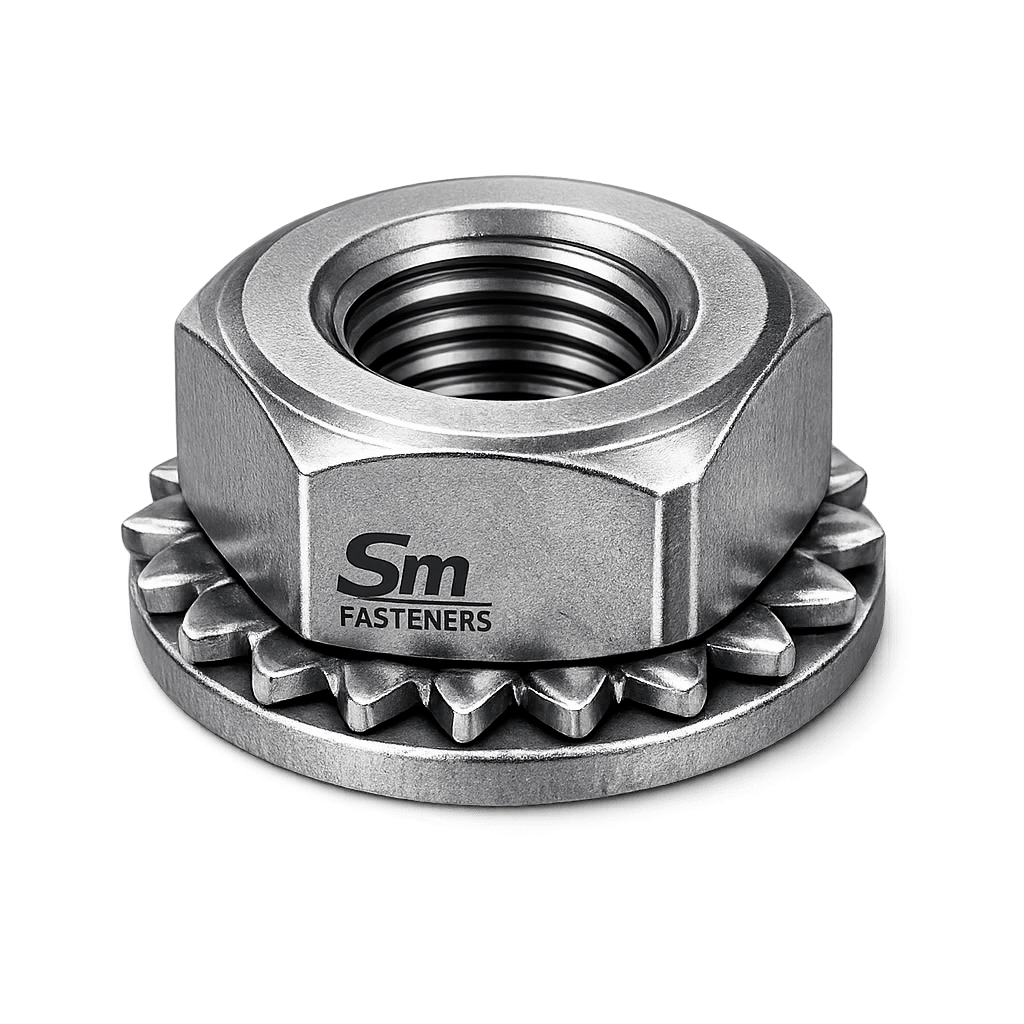
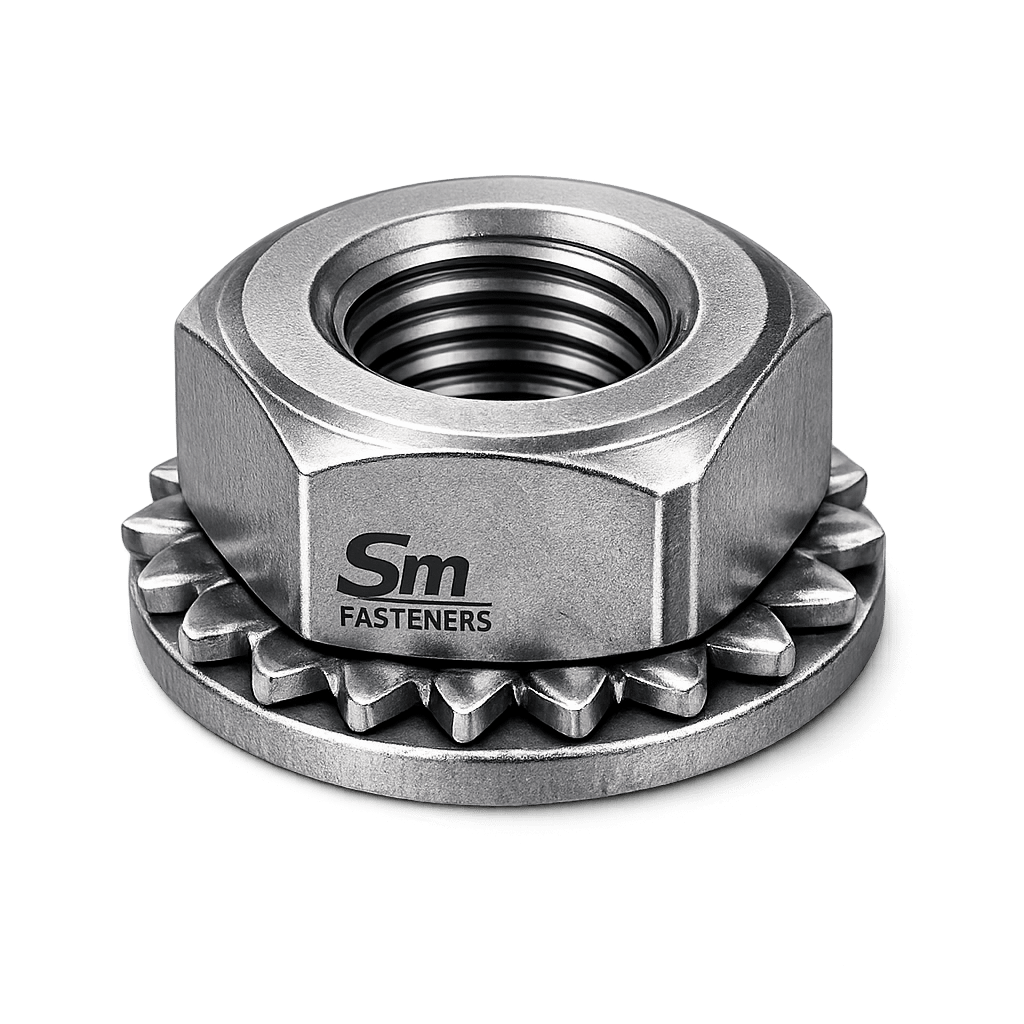
The Kep Nut, also known as a Lock Washer Nut, represents a standardized engineered solution combining:
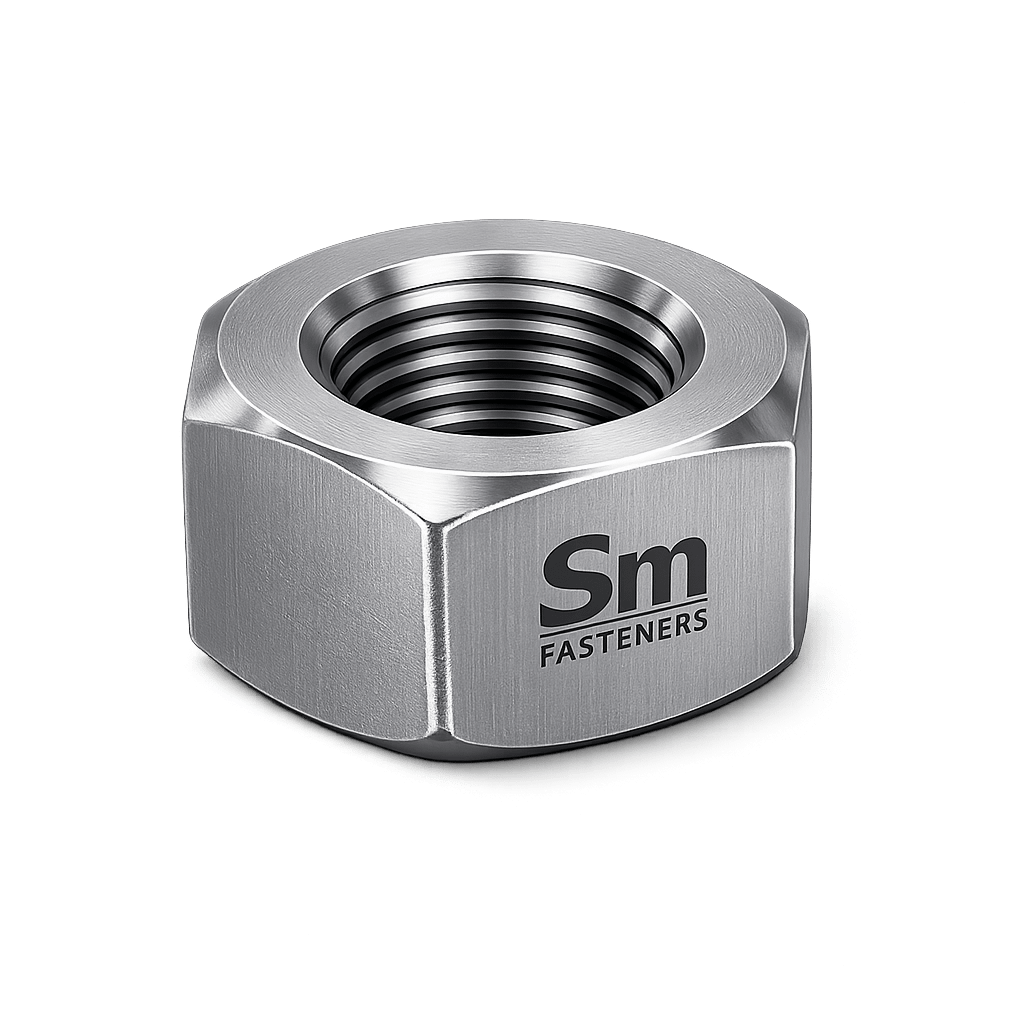
- Hex Nut
- Free-spinning external tooth lock washer
- Integrated vibration resistance
This configuration is widely adopted across:
- Structural fabrication
- Automotive production
- Electrical equipment
- Heavy machinery
- Rail infrastructure
- Oil & gas auxiliary systems
- OEM mass assembly operations
Industrial Drivers Behind Kep Nut Adoption
| Industry Requirement | Kep Nut Advantage |
|---|---|
| High-speed assembly lines | One-piece installation |
| Vibration environments | Mechanical locking action |
| Reduced part count | Integrated washer |
| Controlled preload | Increased friction stabilization |
| Maintenance reliability | Resistance to self-loosening |
SM Fasteners manufactures Kep Nuts under ISO 9001 certified quality systems, ensuring dimensional consistency, mechanical integrity, and global interchangeability required by EPC contractors and OEM buyers.
2. Technical Definition
Engineering Definition
A Kep Nut (Lock Washer Nut) is:
A hexagonal threaded fastener incorporating a permanently assembled free-spinning external or internal tooth lock washer designed to increase frictional resistance and prevent loosening under vibration or cyclic loading.
Functional Elements
| Component | Function |
|---|---|
| Hex Nut Body | Provides primary clamping force |
| Captive Lock Washer | Generates anti-rotation resistance |
| Serrated Teeth | Penetrate mating surface coating |
| Internal Thread | Converts torque into preload |
| Bearing Face | Distributes compressive load |
Terminology
Common industrial names include:
- Kep Nut
- Keps Nut
- Lock Washer Nut
- Washer Face Nut
- External Tooth Lock Nut
- Captive Washer Nut
Operating Principle
Unlike prevailing torque locknuts (nylon insert or distorted thread types), Kep Nuts rely on:
Surface friction enhancement + elastic washer action
Mechanism:
- Nut torque produces axial preload.
- Washer teeth embed into mating surface.
- Rotational resistance increases.
- Vibrational back-off is suppressed.
Mechanical Locking Concept
Self-loosening occurs when transverse vibration reduces thread friction (Junker effect).
Kep Nut counteracts this through:
- Increased friction coefficient (μ)
- Micro-interlocking of teeth
- Energy dissipation at interface
3. Functional Role in Bolted Assemblies
Kep Nuts serve dual engineering purposes:
3.1 Primary Function — Clamp Load Generation
The nut converts applied torque into axial clamping force:
Where:
| Symbol | Meaning |
|---|---|
| Preload force | |
| Applied torque | |
| Nut factor | |
| Nominal diameter |
3.2 Secondary Function — Locking Stability
The washer introduces:
- Increased friction torque
- Rotation resistance
- Load retention under vibration
4. Load Mechanics & Force Behavior
Understanding Kep Nut performance requires evaluation of force distribution within the bolted joint.
4.1 Force Transmission Path
4.2 Preload Importance
Approximately 85–90% of applied torque is lost to friction:
| Energy Distribution | Percentage |
|---|---|
| Thread friction | 40–50% |
| Bearing friction | 35–45% |
| Useful preload | 10–15% |
The lock washer increases bearing friction intentionally to improve anti-loosening performance.
4.3 Clamping Force Behavior
When tightened:
- Bolt stretches elastically
- Joint compresses
- Stored elastic energy maintains clamping force
Kep Nuts improve preload retention rather than increasing strength.
4.4 Vibration Resistance Mechanism
Under transverse vibration:
| Standard Nut | Kep Nut |
|---|---|
| Rapid preload decay | Stable preload |
| Rotation possible | Tooth engagement resists motion |
| Washer displacement | Washer captive |
4.5 Load Types Acting on Kep Nuts
| Load Type | Effect |
|---|---|
| Axial tensile | Primary design load |
| Shear | Transferred via joint friction |
| Dynamic vibration | Main locking requirement |
| Thermal expansion | Compensated by elastic washer |
| Shock loading | Improved retention |
5. Joint Design Principles
Correct Kep Nut selection depends on joint engineering rather than fastener strength alone.
5.1 Recommended Joint Conditions
Kep Nuts are ideal where:
- Thin sheet metal assemblies exist
- Automated installation required
- Washer loss risk must be eliminated
- Medium locking performance acceptable
5.2 Not Recommended Applications
| Condition | Reason |
|---|---|
| Hardened mating surfaces (>40 HRC) | Teeth cannot embed |
| Critical structural tension joints | Limited prevailing torque |
| Repeated disassembly cycles | Tooth wear reduces locking |
| Soft non-metal surfaces | Surface damage risk |
5.3 Minimum Thread Engagement
Engineering rule:Le≥1.0×D
Where:
- = engagement length
- = nominal diameter
For softer materials:
5.4 Joint Stiffness Relationship
Bolt and joint behave as springs:
Where:
| Term | Meaning |
|---|---|
| Bolt stiffness | |
| Joint stiffness | |
| Load sharing factor |
Higher joint stiffness improves Kep Nut locking effectiveness.
5.5 Frictional Locking Contribution
Total resistance torque:
Where:
- = thread friction torque
- = washer tooth resistance
5.6 Preload Loss Factors
| Cause | Impact |
|---|---|
| Embedment relaxation | Initial preload drop |
| Surface coating creep | Gradual loss |
| Thermal cycling | Expansion mismatch |
| Vibration | Self-loosening |
Kep Nuts specifically mitigate vibration-induced loosening.
6. Torque–Tension Relationship
Kep Nut assemblies exhibit slightly higher nut factors due to washer friction.
Typical values:
| Condition | Nut Factor (K) |
|---|---|
| Plain steel | 0.18–0.20 |
| Zinc plated | 0.20–0.24 |
| Lubricated | 0.15–0.17 |
| Stainless steel | 0.22–0.28 |
This must be accounted for during torque specification.
7. Failure Mechanisms Relevant to Kep Nuts
7.1 Self-Loosening (Junker Effect)
Cause:
- Transverse joint movement.
Mitigation:
- Washer teeth friction.
- Increased bearing resistance.
7.2 Fatigue Failure
Occurs when preload is insufficient.
Symptoms:
- Crack initiation at thread root.
Prevention:
- Correct torque application.
- Proper property class selection.
7.3 Surface Galling (Stainless Steel)
Risk factors:
- High friction
- Similar metallurgy
Control methods:
- Anti-seize compounds
- Controlled torque speeds
7.4 Washer Tooth Wear
Repeated reuse reduces locking efficiency.
Engineering recommendation:
- Replace after multiple service cycles.
7.5 Hydrogen Embrittlement
Relevant for:
- High strength carbon/alloy steel Kep Nuts
- Electroplated coatings
Mitigation (SM Fasteners practice):
- Controlled plating processes
- Post-plate baking
- ISO-compliant hardness limits
8. Selection Criteria — Engineering Perspective
Engineers should evaluate:
| Parameter | Selection Consideration |
|---|---|
| Bolt grade | Match property class |
| Environment | Corrosion resistance |
| Surface hardness | Tooth engagement ability |
| Vibration severity | Locking effectiveness |
| Temperature | Material capability |
| Assembly speed | Automation compatibility |
| Maintenance access | Long-term retention |
9. Advantages in Industrial Procurement
Kep Nuts simplify global sourcing programs.
Procurement Benefits
- Reduced BOM complexity
- Faster installation
- Lower assembly error probability
- Standardized inventory control
- Improved repeatability
SM Fasteners supports EPC procurement through:
- ISO 9001 quality assurance
- MSME manufacturing traceability
- UKAF certification alignment
- Custom material engineering
- Global logistics readiness
10. Engineering Summary
Kep Nuts function as integrated locking fasteners designed to maintain clamp load stability in vibration-prone assemblies while improving installation efficiency.
Key engineering conclusions:
Best suited for medium locking applications requiring rapid assembly and reliable preload retention.
Locking achieved through frictional resistance rather than prevailing torque deformation.
Performance depends heavily on joint design and surface conditions.
Proper torque calculation remains essential.
11. Product Types and Variants
Kep Nuts are produced in multiple engineered configurations to address differences in:
- Load requirement
- Surface hardness
- Assembly accessibility
- Corrosion exposure
- Automation compatibility
- Electrical grounding needs
SM Fasteners manufactures Kep Nuts in standardized and custom configurations aligned with global industrial specifications.
11.1 External Tooth Kep Nut (Type K)
Description
The most widely used configuration featuring an external tooth lock washer attached beneath the hex nut.
Functional Characteristics
| Feature | Engineering Effect |
|---|---|
| External radial teeth | Aggressive surface penetration |
| Larger contact diameter | Improved load distribution |
| High friction coefficient | Strong anti-rotation resistance |
| Free-spinning washer | Maintains alignment during tightening |
Typical Applications
- Sheet metal assemblies
- Electrical panels
- Automotive structures
- HVAC equipment
- Rail coach fabrication
11.2 Internal Tooth Kep Nut
Description
Washer teeth located internally toward the nut center.
Engineering Behavior
| Attribute | Performance |
|---|---|
| Reduced outer diameter | Flush installation |
| Lower surface damage | Suitable for coated parts |
| Controlled bite action | Electrical bonding |
Applications
- Electronics enclosures
- Instrument panels
- Precision assemblies
11.3 Conical Tooth Kep Nut
Designed for improved spring action.
Advantages
- Higher elastic recovery
- Better thermal cycling performance
- Improved preload retention
Used in:
- Vibratory equipment
- Compressors
- Industrial machinery
11.4 Heavy Pattern Kep Nut
Features:
- Increased nut height
- Larger washer thickness
- Higher proof load capability
Applications:
- Heavy equipment
- Structural attachments
- Power generation assemblies
11.5 Stainless Steel Kep Nut
Designed for corrosion-critical environments.
Common grades:
- A2-70
- A4-80
- Duplex stainless
- SMO 254
- Nickel alloys
Typical industries:
- Offshore platforms
- Marine systems
- Chemical processing plants
- LNG terminals
11.6 PEEK Kep Nut (High-Performance Polymer Variant)
SM Fasteners supports advanced engineering programs requiring metal replacement fasteners.
Characteristics
| Property | Performance |
|---|---|
| Material | PEEK polymer |
| Weight | ~70% lighter than steel |
| Electrical insulation | Excellent |
| Chemical resistance | Outstanding |
| Temperature capability | Up to 260°C |
| Non-magnetic | Yes |
Applications:
- Semiconductor equipment
- Medical systems
- Aerospace electronics
- Battery manufacturing lines
12. Geometry and Dimensional Logic
The geometry of a Kep Nut directly influences:
- Load distribution
- Washer engagement
- Torque behavior
- Locking efficiency
12.1 Primary Geometric Elements
| Parameter | Description |
|---|---|
| Thread diameter (d) | Nominal fastener size |
| Pitch (P) | Thread spacing |
| Across flats (s) | Wrench size |
| Nut height (m) | Load capacity |
| Washer OD (dw) | Contact area |
| Tooth height | Locking penetration depth |
| Washer thickness | Elastic response |
12.2 Engineering Design Considerations
Washer Diameter Ratio
Larger washer diameters:
- Reduce bearing stress
- Improve vibration resistance
Bearing Stress Calculation
Where:
- = preload force
- = bearing area
Kep Nuts reduce localized stress concentration compared with standard nuts.
13. Standard Dimensional Specification Table (Metric Series)
(Typical engineering reference values — SM Fasteners manufacturing tolerances comply with ISO requirements.)
| Size | Pitch (mm) | Across Flats (mm) | Nut Height (mm) | Washer OD (mm) | Approx Weight (g/pc) |
|---|---|---|---|---|---|
| M3 | 0.5 | 5.5 | 2.4 | 7 | 0.3 |
| M4 | 0.7 | 7 | 3.2 | 9 | 0.6 |
| M5 | 0.8 | 8 | 4.0 | 10 | 1.0 |
| M6 | 1.0 | 10 | 5.0 | 12 | 1.8 |
| M8 | 1.25 | 13 | 6.5 | 16 | 3.5 |
| M10 | 1.5 | 17 | 8.0 | 20 | 6.5 |
| M12 | 1.75 | 19 | 10 | 24 | 10.5 |
| M16 | 2.0 | 24 | 13 | 30 | 24 |
| M20 | 2.5 | 30 | 16 | 36 | 45 |
14. Thread Systems and Tolerances
Kep Nuts must maintain full compatibility with international bolt standards.
14.1 Supported Thread Standards
| Standard | System | Typical Use |
|---|---|---|
| ISO 261 / ISO 965 | Metric | Global industrial |
| ASME B1.1 | UNC / UNF | USA projects |
| BS 84 | BSW | Legacy British equipment |
| BSF | Fine thread | Precision assemblies |
| DIN 13 | Metric | European machinery |
14.2 Thread Tolerance Classes
| Thread Type | Nut Class | Bolt Class |
|---|---|---|
| Metric | 6H | 6g |
| UNC | 2B | 2A |
| UNF | 2B | 2A |
| Precision | 4H | 4g |
SM Fasteners ensures gauge verification using calibrated GO/NO-GO thread gauges under ISO 9001 inspection procedures.
15. Applicable International Standards
Kep Nuts are governed by several dimensional and performance standards.
15.1 DIN Standards
| Standard | Description |
|---|---|
| DIN 985 (reference concept) | Locknut design basis |
| DIN 6923 | Flange nut geometry reference |
| DIN 6798 | Lock washer tooth design |
| DIN 934 | Hex nut dimensional reference |
15.2 ISO Standards
| ISO Standard | Scope |
|---|---|
| ISO 4032 | Hex nuts — style 1 |
| ISO 898-2 | Mechanical properties of nuts |
| ISO 3269 | Acceptance inspection |
| ISO 4759 | Tolerances |
| ISO 10683 | Coating requirements |
15.3 ASTM / ASME Standards
| Standard | Application |
|---|---|
| ASTM A563 | Carbon steel nuts |
| ASTM A194 | Alloy steel/high temperature |
| ASTM F594 | Stainless steel nuts |
| ASME B18.2.2 | Inch series hex nuts |
| ASTM B633 | Zinc plating |
15.4 British Standards
| Standard | Application |
|---|---|
| BS 4190 | Hex nut dimensions |
| BS 3692 | Metric fasteners |
| BS EN ISO series | Harmonized European standards |
16. Property Class Systems
Kep Nuts must match bolt strength grades.
16.1 Metric Property Classes
| Nut Property Class | Compatible Bolt Class |
|---|---|
| 5 | 5.8 bolts |
| 8 | 8.8 bolts |
| 10 | 10.9 bolts |
| 12 | 12.9 bolts |
16.2 Proof Load Requirements
Nuts must withstand proof stress without thread stripping.
| Property Class | Proof Stress (MPa) |
|---|---|
| 5 | 500 |
| 8 | 800 |
| 10 | 1000 |
| 12 | 1200 |
17. Inch Series Kep Nuts (UNC / UNF)
Common EPC project requirement.
| Size | Thread | Across Flats | Height | Washer OD |
|---|---|---|---|---|
| #6 | 32 UNC | 1/4″ | 7/64″ | 3/8″ |
| #8 | 32 UNC | 11/32″ | 1/8″ | 7/16″ |
| 1/4″ | 20 UNC | 7/16″ | 7/32″ | 5/8″ |
| 5/16″ | 18 UNC | 1/2″ | 1/4″ | 3/4″ |
| 3/8″ | 16 UNC | 9/16″ | 5/16″ | 7/8″ |
| 1/2″ | 13 UNC | 3/4″ | 7/16″ | 1-1/8″ |
18. Dimensional Interchangeability Considerations
Engineering teams must consider:
- Washer diameter variations among manufacturers
- Tooth geometry differences
- Surface finish impact on torque values
- Metric vs inch assembly compatibility
SM Fasteners maintains interchangeability through:
- Statistical process control
- Calibrated tooling
- Standard-compliant dies
- Batch traceability
19. Engineering Geometry Impact on Performance
| Geometry Parameter | Influence |
|---|---|
| Washer thickness | Elastic recovery |
| Tooth angle | Locking strength |
| Nut height | Load capacity |
| Thread tolerance | Torque accuracy |
| Bearing diameter | Surface pressure control |
20. Weight Chart — SM Fasteners Reference
(Aligned with industrial packaging and logistics planning.)
| Size | Weight / Piece (kg) | Weight / 100 pcs (kg) |
|---|---|---|
| M4 | 0.0006 | 0.06 |
| M5 | 0.0010 | 0.10 |
| M6 | 0.0018 | 0.18 |
| M8 | 0.0035 | 0.35 |
| M10 | 0.0065 | 0.65 |
| M12 | 0.0105 | 1.05 |
| M16 | 0.024 | 2.4 |
| M20 | 0.045 | 4.5 |
Used by SM Fasteners export logistics teams for pallet optimization and EPC shipment forecasting.
21. Engineering Summary
Kep Nuts are engineered fastening components whose performance is governed by:
- Integrated washer geometry
- Thread tolerance accuracy
- Standard compliance
- Property class compatibility
- Correct dimensional selection
International standard alignment ensures full interchangeability across global EPC and OEM supply chains.
SM Fasteners delivers Kep Nuts manufactured to ISO, ASTM, DIN, and BS requirements with controlled dimensional accuracy suitable for audited industrial projects.
22. Materials Engineering — Industrial Material Selection
Material selection for Kep Nuts directly determines:
- Load capacity
- Corrosion resistance
- Temperature performance
- Galling resistance
- Service life reliability
SM Fasteners manufactures Kep Nuts across the full industrial alloy spectrum to satisfy EPC project specifications and international procurement requirements.
22.1 Material Families Used in Kep Nuts
| Material Family | Standards | Typical Grades | Primary Use |
|---|---|---|---|
| Carbon Steel | ASTM A563 | Grade A, DH | Structural & general engineering |
| Alloy Steel | ASTM A194 | 2H, 7, L7 | High strength & temperature |
| Stainless Steel | ASTM F594 | A2-70, A4-80 | Corrosion resistance |
| Duplex Stainless | ASTM A479 | 2205 | Offshore & chloride exposure |
| Super Duplex | ASTM A182 | 2507 | Seawater & subsea |
| Nickel Alloys | ASTM B564 | Monel, Inconel | Chemical & LNG |
| SMO 254 | UNS S31254 | Super Austenitic | Marine & desalination |
| PEEK Polymer | ASTM D6262 | Industrial Grade | Electrical & chemical isolation |
22.2 Mechanical Property Comparison Table
| Material | Yield Strength (MPa) | UTS (MPa) | Temp Limit | Corrosion Resistance | Relative Cost | Typical Application |
|—|—|—|—|—|—|
| Carbon Steel 8 | 640 | 800 | 300°C | Low | Low | Structural steel |
| Alloy Steel 10 | 940 | 1040 | 450°C | Moderate | Medium | Power plants |
| Alloy Steel 12 | 1100 | 1220 | 500°C | Moderate | Medium-High | Heavy machinery |
| SS A2-70 | 450 | 700 | 400°C | Good | Medium | General corrosion |
| SS A4-80 | 600 | 800 | 450°C | Excellent | Medium-High | Marine |
| Duplex 2205 | 620 | 850 | 300°C | Very High | High | Offshore |
| Super Duplex 2507 | 800 | 1000 | 300°C | Extreme | Very High | Subsea |
| Inconel 625 | 460 | 830 | 700°C | Exceptional | Premium | LNG/chemical |
| SMO 254 | 650 | 900 | 400°C | Extreme chloride | Premium | Desalination |
| PEEK | — | — | 260°C | Chemical inert | High | Electronics |
22.3 Material Selection Criteria
Engineers must evaluate:
| Parameter | Engineering Consideration |
|---|---|
| Environment | Atmospheric / marine / chemical |
| Required preload | Strength class |
| Temperature | Material stability |
| Hydrogen exposure | NACE compliance |
| Weight reduction | Polymer option |
| Electrical conductivity | Grounding vs insulation |
23. Corrosion Resistance vs Service Environment
| Environment | Carbon Steel | Stainless A2 | Stainless A4 | Duplex | Nickel Alloy | PEEK |
|---|---|---|---|---|---|---|
| Indoor dry | Excellent | Excellent | Excellent | Excellent | Excellent | Excellent |
| Outdoor industrial | Fair | Good | Excellent | Excellent | Excellent | Excellent |
| Marine atmosphere | Poor | Good | Excellent | Excellent | Excellent | Excellent |
| Seawater immersion | Not recommended | Moderate | Good | Excellent | Exceptional | Excellent |
| Acidic chemical plant | Poor | Moderate | Good | Excellent | Exceptional | Excellent |
| H₂S Sour Service | Limited | Conditional | Good | Excellent | Excellent | Immune |
| LNG cryogenic | Limited | Good | Good | Excellent | Excellent | Good |
SM Fasteners supplies Kep Nuts compliant with NACE MR0175 / ISO 15156 for sour service applications when required.
24. Heat Treatment Processes
Heat treatment governs the mechanical performance of high-strength Kep Nuts.
24.1 Carbon & Alloy Steel Heat Treatment Cycle
Process Sequence
- Controlled forging
- Austenitizing
- Quenching
- Tempering
- Hardness verification
Heat Treatment Objective
| Process | Engineering Purpose |
|---|---|
| Quenching | Increase strength |
| Tempering | Improve toughness |
| Stress relief | Prevent cracking |
| Hardness control | Avoid brittleness |
24.2 Property Class vs Hardness
| Property Class | Hardness Range (HV) |
|---|---|
| 5 | 120–210 |
| 8 | 200–302 |
| 10 | 272–353 |
| 12 | 353–425 |
SM Fasteners maintains hardness limits aligned with ISO 898-2 requirements.
24.3 Hydrogen Embrittlement Prevention
Critical for plated high-strength Kep Nuts.
SM Fasteners controls risk through:
- Low hydrogen plating chemistry
- Post-plating bake at 190–230°C
- Controlled hardness limits
- Process validation records
24.4 Stainless Steel Processing
Stainless Kep Nuts undergo:
- Solution annealing
- Rapid quenching
- Passivation
Benefits:
- Restores corrosion resistance
- Removes free iron contamination
- Prevents intergranular corrosion
24.5 Heat Treatment for Nickel Alloys
- Precipitation hardening
- Controlled aging cycles
- Grain stabilization
Used for high-temperature and LNG service.
25. End-to-End Manufacturing Workflow
SM Fasteners applies a fully traceable manufacturing system integrated with ISO 9001 quality management.
25.1 Raw Material Verification
Incoming material inspection includes:
- Mill Test Certificate (MTC)
- Heat number verification
- PMI testing
- Chemical composition analysis
- Mechanical property confirmation
25.2 Manufacturing Process Flow
Raw Material → Wire Rod Inspection → Cold Forging
→ Washer Stamping → Assembly → Threading
→ Heat Treatment → Surface Finish → Inspection
→ Marking → Packaging → Dispatch
25.3 Forging Process
Cold Forging Advantages
| Benefit | Engineering Result |
|---|---|
| Grain flow continuity | Higher fatigue strength |
| Reduced machining | Dimensional consistency |
| Improved surface finish | Better coating adhesion |
25.4 Washer Manufacturing
Lock washers are produced through:
- Progressive stamping
- Precision tooth forming
- Hardness control
- Spring elasticity verification
Washer is permanently assembled yet free-spinning.
25.5 Thread Production
Thread Rolling (Preferred)
| Parameter | Benefit |
|---|---|
| Compressive grain flow | Increased fatigue life |
| Smooth surface | Lower stress concentration |
| Improved accuracy | Torque repeatability |
Thread Cutting (Special Cases)
Used for:
- Large diameters
- Exotic alloys
- Low production volumes
25.6 Assembly Integration
The washer is mechanically retained before finishing operations ensuring:
- No field washer loss
- Automation compatibility
- Controlled rotational freedom
26. Surface Engineering & Coatings
Surface treatment determines long-term performance.
26.1 Surface Finish Comparison Table
| Coating | Thickness | Corrosion Resistance | Temperature Limit | Typical Use |
|---|---|---|---|---|
| Plain Oil | Minimal | Low | 200°C | Indoor equipment |
| Zinc Electroplated | 5–12 µm | Moderate | 120°C | General industrial |
| Zinc Flake | 8–12 µm | High | 180°C | Automotive |
| Hot Dip Galvanized | 40–70 µm | Very High | 200°C | Structural steel |
| Mechanical Galvanized | 20–40 µm | High | 200°C | Construction |
| Phosphate | Thin | Moderate | 300°C | Pre-lubricated |
| PTFE / Xylan | Thin | Excellent | 260°C | Chemical plants |
| Dacromet / Geomet | Thin | Very High | 300°C | Offshore |
| Passivation (SS) | — | Restores CR | 400°C | Stainless fasteners |
26.2 Coating Selection Guidelines
| Requirement | Recommended Finish |
|---|---|
| Outdoor structures | HDG |
| Automotive vibration | Zinc flake |
| Chemical exposure | PTFE |
| Offshore platform | Geomet |
| Stainless applications | Passivated finish |
26.3 Friction Coefficient Impact
Coatings influence torque values.
| Surface Condition | Friction Coefficient |
|---|---|
| Dry steel | 0.20 |
| Zinc plated | 0.22 |
| Lubricated | 0.15 |
| PTFE coated | 0.10–0.12 |
Engineering torque values must be adjusted accordingly.
26.4 Galvanic Compatibility Considerations
Avoid dissimilar metal pairing.
| Combination | Risk |
|---|---|
| Carbon steel + Aluminum | High corrosion risk |
| Stainless + Carbon steel | Moderate |
| Duplex + Duplex | Safe |
| PEEK + Any metal | Electrically isolated |
27. Manufacturing Traceability & Identification
SM Fasteners maintains full traceability through:
- Heat number marking
- Batch coding
- ERP tracking
- Inspection linkage
- Material certification traceability
28. Engineering Summary
The reliability of Kep Nuts depends on:
- Correct material engineering
- Controlled heat treatment
- Precision cold forming
- Accurate thread production
- Environment-specific surface coatings
SM Fasteners integrates advanced metallurgy, certified manufacturing systems, and specialized materials—including Duplex, Nickel Alloys, and PEEK fasteners—to meet demanding industrial project requirements worldwide.
29. Inspection & Quality Control System
Kep Nuts used in industrial assemblies must demonstrate verified mechanical integrity, dimensional conformity, and traceable manufacturing history.
SM Fasteners operates under an ISO 9001 certified Quality Management System, supported by MSME manufacturing traceability and UKAF-aligned certification practices.
29.1 Incoming Material Inspection
Every production batch begins with controlled verification.
| Inspection Stage | Verification Method | Standard Reference |
|---|---|---|
| Material chemistry | Spectrometer / PMI | ASTM / EN |
| Heat number validation | MTC cross-check | EN 10204 |
| Mechanical properties | Tensile testing | ISO 898-2 |
| Surface condition | Visual inspection | ISO 3269 |
| Raw stock dimensions | Calibrated gauges | ISO 4759 |
29.2 In-Process Quality Controls
| Process | Inspection Activity |
|---|---|
| Cold forging | Dimensional sampling |
| Washer stamping | Tooth geometry verification |
| Thread rolling | GO/NO-GO gauges |
| Heat treatment | Hardness testing |
| Coating | Thickness measurement |
| Assembly | Washer rotation validation |
Statistical Process Control (SPC) ensures repeatable production.
29.3 Final Inspection Protocol
Final inspection ensures EPC-ready delivery.
| Test | Purpose |
|---|---|
| Visual inspection | Surface defects |
| Dimensional inspection | Standard compliance |
| Proof load testing | Thread stripping resistance |
| Torque test | Functional locking validation |
| Coating thickness | Corrosion protection |
| Marking verification | Traceability |
29.4 Mechanical Testing
Proof Load Testing
Confirms nut withstands required axial force without deformation.
Hardness Testing
Methods:
- Rockwell
- Vickers
- Brinell
Functional Lock Test
Verifies washer teeth provide resistance against rotation.
29.5 Non-Destructive Testing (When Required)
| Method | Application |
|---|---|
| Magnetic Particle Inspection | Crack detection |
| Dye Penetrant | Surface flaws |
| Ultrasonic Testing | Large forged parts |
| PMI Testing | Alloy confirmation |
29.6 Documentation & Certification
SM Fasteners supplies complete inspection documentation:
- EN 10204 3.1 / 3.2 Material Test Certificate
- Heat treatment reports
- Coating certification
- Dimensional inspection reports
- Certificate of Conformity (CoC)
- Third-party inspection (TPI) approvals
30. Industry Applications
Kep Nuts are primarily used where vibration resistance and assembly efficiency are required.
30.1 Construction & Structural Steel
Applications:
- Steel framing systems
- Modular buildings
- Equipment supports
- HVAC installations
Engineering Benefit:
Integrated washer eliminates installation error.
30.2 Oil & Gas Industry
Upstream
- Control panels
- Skid-mounted equipment
- Instrumentation brackets
Midstream
- Pump assemblies
- Pipeline auxiliary equipment
Downstream
- Refinery equipment housings
- Maintenance access systems
Materials:
- A4 stainless
- Duplex
- Alloy steel
NACE MR0175 compliant options available.
30.3 Power Generation
Used in:
- Turbine enclosures
- Generator housings
- Cable tray supports
- Electrical cabinets
Performance Need:
Vibration resistance under rotating machinery loads.
30.4 Petrochemical & Chemical Processing
Preferred features:
- Reduced component count
- Chemical-resistant materials
- PTFE-coated variants
30.5 LNG & Offshore Platforms
Critical requirements:
- Corrosion resistance
- Salt spray durability
- Long service intervals
Materials supplied by SM Fasteners:
- Super Duplex
- Inconel
- SMO 254
30.6 Automotive & Heavy Equipment
Advantages:
- High-speed robotic assembly
- Reduced inventory handling
- Consistent torque performance
Typical uses:
- Body panels
- Engine accessories
- Chassis attachments
30.7 Railways & Infrastructure
Applications:
- Signal equipment
- Rolling stock interiors
- Control enclosures
30.8 Shipbuilding & Marine Systems
Benefits:
30.9 PEEK Kep Nut Applications
Used where metal fasteners cannot operate:
- Semiconductor fabrication
- Battery production equipment
- Medical machinery
- High purity chemical systems
Advantages:
- Non-conductive
- Non-magnetic
- Chemical inertness
31. Export Capability & Global Supply
SM Fasteners supports international EPC procurement programs.
31.1 Industrial Packaging
| Method | Purpose |
|---|---|
| VCI packaging | Corrosion prevention |
| Thread protection | Damage prevention |
| Lot identification | Traceability |
| Moisture barrier bags | Export protection |
31.2 Export Crating
- ISPM-15 compliant wooden crates
- Palletized loading
- Shock-resistant packaging
- Container optimization using weight charts
31.3 Export Documentation Package
Each shipment may include:
- Commercial invoice
- Packing list
- EN 10204 3.1 MTC
- Heat treatment report
- Coating report
- Inspection release note
- Country of origin certificate
- Third-party inspection approval
32. Mechanical Properties Table (Property Class)
| Property Class | Proof Load (MPa) | Minimum Tensile Strength (MPa) | Hardness Range |
|---|---|---|---|
| 5 | 500 | 500 | 120–210 HV |
| 8 | 800 | 800 | 200–302 HV |
| 10 | 1000 | 1040 | 272–353 HV |
| 12 | 1200 | 1220 | 353–425 HV |
33. Proof Load & Tensile Capacity by Size (Metric Example)
| Size | Property Class 8 Proof Load (kN) | Property Class 10 Proof Load (kN) |
|---|---|---|
| M6 | 8.0 | 10.0 |
| M8 | 15.0 | 19.0 |
| M10 | 24.0 | 30.0 |
| M12 | 35.0 | 44.0 |
| M16 | 70.0 | 87.0 |
| M20 | 110.0 | 140.0 |
34. Tightening Torque Chart
(Typical engineering reference values — dry condition)
| Size | Grade 8 Torque (Nm) | Grade 10 Torque (Nm) | Lubricated Torque (Nm) |
|---|---|---|---|
| M6 | 10 | 14 | 8 |
| M8 | 25 | 35 | 20 |
| M10 | 50 | 70 | 40 |
| M12 | 85 | 120 | 70 |
| M16 | 210 | 290 | 170 |
| M20 | 410 | 560 | 330 |
35. Preload Calculation — Engineering Formula
Governing Equation
Where:
| Symbol | Meaning |
|---|---|
| | Preload Force |
| Applied Torque | |
| Nut Factor | |
| Nominal Diameter |
Worked Example
Given
- Kep Nut Size: M10
- Torque = 50 Nm
- Nut factor
- Diameter
Result:
Approximate clamp load = 25 kN
36. Thread Standards & Tolerance Table
| Thread System | Standard | Nut Tolerance | Bolt Tolerance |
|---|---|---|---|
| Metric Coarse | ISO 965 | 6H | 6g |
| Metric Fine | ISO 965 | 6H | 6g |
| UNC | ASME B1.1 | 2B | 2A |
| UNF | ASME B1.1 | 2B | 2A |
| BSW | BS 84 | Medium | Medium |
| BSF | BS 84 | Medium | Medium |
37. Surface Finish Performance Comparison
| Coating | Salt Spray Resistance | Friction Stability | Reusability | Offshore Suitability |
|---|---|---|---|---|
| Zinc Plated | 72–120 hrs | Moderate | Medium | Limited |
| HDG | 500+ hrs | High friction | High | Good |
| Zinc Flake | 600–1000 hrs | Stable | High | Excellent |
| PTFE | Excellent | Low friction | High | Excellent |
| Passivated SS | Excellent | Stable | High | Excellent |
38. Weight Chart — SM Fasteners Logistics Reference
| Size | Weight/Piece (kg) | Weight/100 pcs (kg) |
|---|---|---|
| M5 | 0.0010 | 0.10 |
| M6 | 0.0018 | 0.18 |
| M8 | 0.0035 | 0.35 |
| M10 | 0.0065 | 0.65 |
| M12 | 0.0105 | 1.05 |
| M16 | 0.024 | 2.4 |
| M20 | 0.045 | 4.5 |
Used for EPC logistics planning and container loading optimization.
39. Failure Prevention Guidelines
| Failure Mode | Prevention Method |
|---|---|
| Self-loosening | Correct torque + washer engagement |
| Fatigue cracking | Maintain adequate preload |
| Galling | Lubrication or coating |
| Hydrogen embrittlement | Controlled plating |
| Stress corrosion cracking | Proper alloy selection |
40. SM Fasteners Engineering Capability
SM Fasteners demonstrates full industrial readiness through:
- ISO 9001 certified manufacturing
- MSME registered production systems
- UKAF-aligned certification framework
- Advanced material capability including:
- Duplex & Super Duplex
- Nickel Alloys
- SMO 254
- PEEK Fasteners
- Custom fastener engineering
- EPC project documentation compliance
- Global export logistics capability
41. Final Engineering Conclusion
Kep Nuts (Lock Washer Nuts) represent a highly efficient fastening solution combining:
- Reliable clamp load generation
- Integrated locking functionality
- Reduced assembly complexity
- Improved vibration resistance
When engineered correctly—through material selection, torque control, coating specification, and quality verification—they provide dependable performance across heavy industrial environments.
Through certified manufacturing systems, advanced metallurgy capability, and rigorous inspection practices, SM Fasteners delivers Kep Nuts suitable for globally audited engineering projects requiring precision, reliability, and full standards compliance.