

LAG BOLT
1. Industry Context of Lag Bolts
1.1 Evolution of Heavy-Duty Wood & Structural Fastening
Lag bolts (commonly termed lag screws or coach screws) represent one of the oldest engineered fastening systems used where high withdrawal resistance and direct load transfer into non-tapped substrates are required.
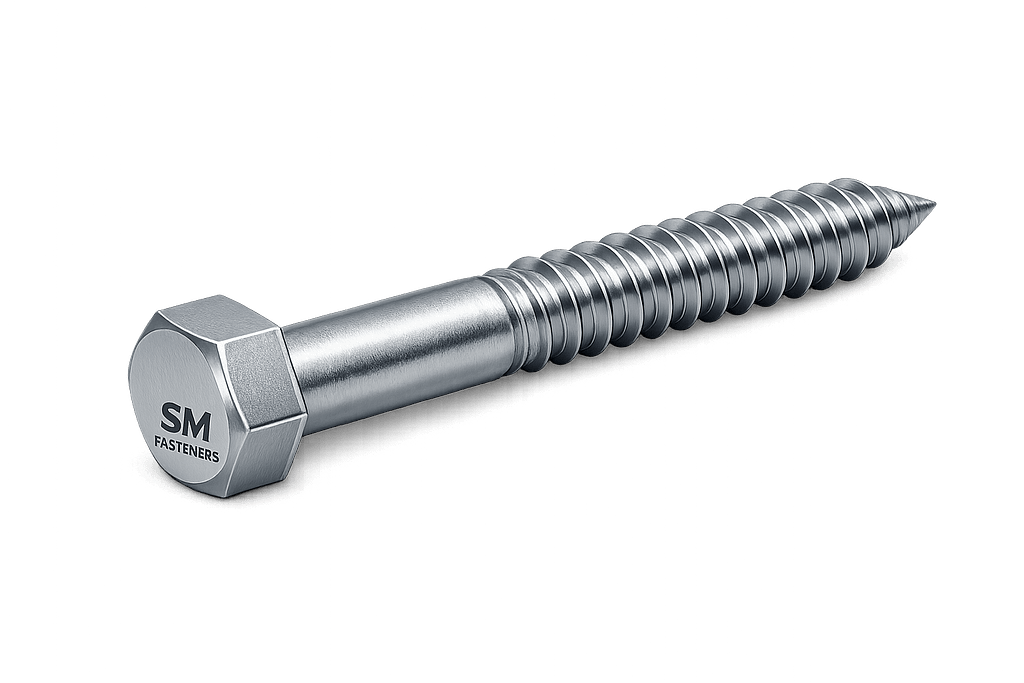
Historically used in timber construction, modern lag bolts have evolved into industrial structural fasteners deployed across:
- Structural steel-to-timber transitions
- Heavy equipment foundations
- Rail infrastructure
- Power transmission structures
- Marine and offshore installations
- Mechanical mounting systems
- Composite structural assemblies
Unlike conventional machine bolts requiring nuts, lag bolts generate holding force through:
- Thread engagement within substrate material
- Radial compression
- Frictional resistance
- Material shear strength interaction
Today’s EPC projects require lag bolts manufactured to controlled mechanical properties and dimensional tolerances rather than traditional construction hardware standards.
1.2 Role in Modern Industrial Assemblies
Lag bolts are selected when:
| Requirement | Engineering Need |
|---|---|
| One-side installation | No backside access |
| High pull-out strength | Structural anchoring |
| Thick substrates | Timber, laminated beams, composites |
| Vibration resistance | Equipment mounting |
| Rapid installation | Field erection environments |
| Retrofit capability | Maintenance & repair work |
Industries increasingly integrate lag bolts into hybrid assemblies combining:
- Steel
- Laminated timber
- Polymer composites
- Fiber-reinforced structures
- Equipment skid bases
1.3 Industrial Sectors Using Lag Bolts
Construction & Structural Engineering
- Timber-to-steel structural nodes
- Roof truss anchoring
- Glulam and LVL beam connections
- Bridge decking systems
Oil & Gas Sector
- Temporary structural supports
- Cable tray supports
- Modular buildings
- Equipment skids
Power Generation
- Transformer platforms
- Cooling tower timber frames
- Cable management structures
Petrochemical & Chemical Plants
- Access platforms
- Pipe rack support assemblies
- Non-weld structural mounting
Railways & Infrastructure
- Sleepers
- Signal mounting
- Sound barriers
Marine & Shipbuilding
- Deck hardware
- Fender systems
- Dock installations
Heavy Equipment & OEM Manufacturing
- Machine base mounting
- Transportation equipment
2. Technical Definition of Lag Bolt
2.1 Engineering Definition
A Lag Bolt is defined as:
A heavy-duty externally threaded fastener with a hexagonal or square head designed to be driven into a pre-drilled hole without mating nut engagement, generating clamping force through thread embedding within the base material.
Key engineering characteristics:
- Coarse deep threads
- Large shank diameter
- High shear capability
- High withdrawal resistance
- Partial thread configuration
- Torque-driven installation
2.2 Structural Geometry
Primary geometric elements include:
| Component | Function |
|---|---|
| Head | Torque transmission |
| Bearing Surface | Load distribution |
| Unthreaded Shank | Shear resistance |
| Thread Section | Pull-out resistance |
| Tip | Material penetration |
Unlike machine bolts, lag bolts form their own internal mating threads during installation.
2.3 Difference from Other Fasteners
| Fastener Type | Nut Required | Substrate Type | Load Mechanism |
|---|---|---|---|
| Machine Bolt | Yes | Metal | Clamp tension |
| Stud Bolt | Yes | Flanged joints | Preload |
| Anchor Bolt | Embedded | Concrete | Expansion/Bond |
| Wood Screw | No | Wood | Light duty |
| Lag Bolt | No | Timber/Composite | Embedment + Clamp |
Lag bolts operate as a hybrid between:
- Structural screw
- Anchor system
- Shear connector
2.4 Thread Functionality
Lag bolt threads are engineered to maximize:
- Material displacement
- Fiber compression
- Load transfer area
Characteristics:
- Large thread depth
- Wide pitch spacing
- Reduced stripping risk
- Enhanced withdrawal resistance
Thread geometry directly influences installation torque and holding strength.
3. Load Mechanics & Force Behavior
Understanding lag bolt performance requires analysis of combined loading conditions rather than simple tension.
3.1 Primary Load Types
Lag bolts resist multiple forces simultaneously:
| Load Type | Description |
|---|---|
| Axial Tension | Pull-out force |
| Shear Load | Lateral loading |
| Bending Moment | Offset loads |
| Cyclic Load | Vibration fatigue |
| Compression | Joint clamping |
3.2 Load Transfer Mechanism
Load transfer occurs through three mechanisms:
1. Thread Bearing Stress
Material fibers bear against thread flanks.
2. Frictional Resistance
Generated by installation torque.
3. Clamp Force
Produced by elastic elongation of bolt shank.
3.3 Pull-Out Resistance Theory
Withdrawal capacity depends on:
Where:
- D = thread diameter
- Lₑ = effective embedment length
- S = substrate shear strength
Critical design variable:
👉 Embedment depth governs performance more than diameter alone.
3.4 Shear Load Behavior
Lag bolts frequently operate under shear.
Shear resistance governed by:
- Shank diameter
- Material grade
- Bearing capacity of substrate
- Edge distance
Design engineers must consider:
- Double shear vs single shear
- Eccentric loading
- Combined tension/shear interaction
3.5 Torque–Tension Relationship
Preload generated during tightening:
Where:
- T = torque
- K = nut factor (friction coefficient)
- F = preload
- D = nominal diameter
Important considerations:
- Timber compressibility reduces retained preload
- Lubrication significantly alters torque values
- Over-torque causes substrate crushing
3.6 Elastic Interaction in Lag Bolt Joints
Unlike metal-to-metal bolted joints:
- Substrate deformation dominates behavior.
- Load redistribution occurs as material creeps.
- Relaxation must be considered.
Lag bolts therefore behave as semi-rigid connections.
3.7 Preload Loss Mechanisms
| Cause | Effect |
|---|---|
| Wood creep | Reduced clamp force |
| Moisture change | Joint relaxation |
| Temperature variation | Expansion mismatch |
| Vibration | Micro-slip |
| Embedment crushing | Torque loss |
Engineering mitigation:
- Increased embedment length
- Hardened washers
- Periodic retightening programs
4. Joint Design Principles
Lag bolt performance depends primarily on correct joint engineering.
4.1 Fundamental Joint Design Objectives
A properly designed lag bolt joint must:
- Maintain clamp load
- Prevent substrate splitting
- Avoid thread stripping
- Resist fatigue
- Enable inspection access
4.2 Pre-Drilling Requirements
Pre-drilling is mandatory for industrial installations.
| Hole Type | Diameter Rule |
|---|---|
| Pilot Hole | 60–75% of root diameter |
| Clearance Hole | Slightly larger than shank |
| Hard Timber | Larger pilot required |
Benefits:
- Prevents cracking
- Ensures torque accuracy
- Improves alignment
- Reduces installation stress
4.3 Edge Distance & Spacing Rules
Minimum spacing guidelines:
| Parameter | Recommended Value |
|---|---|
| Edge distance | ≥ 4 × diameter |
| Bolt spacing | ≥ 7 × diameter |
| End distance | ≥ 7 × diameter |
Failure to maintain spacing leads to:
- Splitting failure
- Reduced load capacity
- Progressive joint failure
4.4 Embedment Length Design
Engineering practice:
Where D = bolt diameter
Higher embedment required for:
- Softwood
- Composite materials
- Dynamic loading
4.5 Washer Requirement
Industrial lag bolt assemblies typically include:
- Hardened flat washer
- Structural plate washer
- Custom bearing plates (heavy loads)
Functions:
- Load distribution
- Surface protection
- Increased preload retention
4.6 Combined Loading Design
Most real applications experience combined loads.
Interaction equation:
Where:
- T = applied tension
- V = applied shear
Used in structural engineering calculations.
4.7 Failure Mechanisms
1. Thread Pull-Out
Insufficient embedment.
2. Shear Fracture
Undersized diameter.
3. Substrate Splitting
Improper spacing.
4. Fatigue Failure
Cyclic loading without preload control.
5. Corrosion-Induced Failure
Environmental mismatch.
4.8 Environmental Engineering Considerations
Lag bolt selection must consider:
- Moisture exposure
- Chemical attack
- Temperature cycling
- Marine salt exposure
- Hydrogen sulfide environments
SM Fasteners supplies lag bolts in advanced materials including:
- Stainless Steel
- Duplex & Super Duplex
- Nickel Alloys
- SMO 254
- PEEK polymer fasteners for electrically isolated or chemically aggressive environments
4.9 Engineering Design Philosophy Adopted by SM Fasteners
Design and manufacturing philosophy integrates:
- ISO 9001 process control
- Traceable raw material sourcing
- Controlled forging and threading
- Mechanical property validation
- Global EPC documentation readiness
Lag bolts supplied are engineered as load-bearing industrial components, not construction hardware.
5. Product Types and Variants of Lag Bolts
Lag bolts supplied for industrial applications are not standardized to a single universal geometry. Instead, configuration is determined by installation method, load direction, substrate characteristics, and environmental service conditions.
SM Fasteners manufactures lag bolts across multiple geometries to support EPC project specifications, OEM requirements, and engineered assemblies.
5.1 Classification by Head Configuration
Head design determines torque transmission efficiency, installation accessibility, and load distribution behavior.
| Head Type | Engineering Characteristics | Typical Applications |
|---|---|---|
| Hex Head Lag Bolt | Standard heavy-duty configuration | Structural framing, machinery mounting |
| Square Head Lag Bolt | High torque transmission | Rail, restoration, heavy timber |
| Flange Head Lag Bolt | Integrated washer effect | Vibration-prone equipment |
| Countersunk Head | Flush installation | Architectural structures |
| Socket Head Lag Bolt | Restricted access areas | OEM assemblies |
| Custom Forged Head | Project-specific | Offshore & EPC systems |
Engineering Note:
Hex head lag bolts remain dominant due to compatibility with calibrated torque tools.
5.2 Classification by Thread Geometry
Lag bolt performance depends primarily on thread design.
| Thread Style | Description | Mechanical Effect |
|---|---|---|
| Coarse Thread | Deep profile | Maximum withdrawal strength |
| Partial Thread | Smooth shank section | Improved shear performance |
| Fully Threaded | Continuous engagement | Thin material assemblies |
| High-Low Thread | Dual pitch geometry | Reduced driving torque |
| Serrated Thread | Cutting edges | Hardwood installation |
SM Fasteners optimizes thread rolling parameters to balance:
- Installation torque
- Substrate damage prevention
- Pull-out capacity
- Fatigue resistance
5.3 Classification by Tip Configuration
| Tip Type | Function |
|---|---|
| Gimlet Point | Self-starting installation |
| Blunt End | Controlled pilot-hole assembly |
| Cone Point | Reduced splitting risk |
| Drill Point (Custom) | Composite installations |
5.4 Functional Variants for Industrial Applications
Structural Lag Bolts
- Heavy diameter
- Long embedment
- Partial thread
- Used in load-bearing assemblies
Equipment Mounting Lag Bolts
- Higher strength grades
- Controlled tolerance threads
- Washer-faced heads
Corrosion-Resistant Lag Bolts
- Stainless & Duplex alloys
- Marine/offshore applications
High-Temperature Lag Bolts
- Nickel alloys
- Furnace & power plant usage
Electrically Non-Conductive Lag Bolts
- PEEK Fasteners
- Explosion-proof installations
- Chemical plants
6. Dimensional Logic & Engineering Geometry
Lag bolt dimensions follow structural load logic rather than aesthetic standardization.
6.1 Fundamental Dimensional Parameters
| Symbol | Parameter | Engineering Role |
|---|---|---|
| D | Nominal Diameter | Shear capacity |
| L | Overall Length | Installation depth |
| Lt | Thread Length | Withdrawal resistance |
| S | Head Width Across Flats | Torque transmission |
| K | Head Height | Tool engagement |
| P | Thread Pitch | Installation torque |
6.2 Standard Dimensional Specification Table
Metric Lag Bolt Dimensions (Engineering Reference)
| Size (mm) | Pitch (mm) | Head AF (mm) | Head Height (mm) | Thread Length (mm) | Typical Length Range |
|---|---|---|---|---|---|
| M6 | 1.0 | 10 | 4 | 18 | 25–80 |
| M8 | 1.25 | 13 | 5.3 | 22 | 30–120 |
| M10 | 1.5 | 17 | 6.4 | 26 | 40–160 |
| M12 | 1.75 | 19 | 7.5 | 30 | 50–200 |
| M16 | 2.0 | 24 | 10 | 38 | 60–300 |
| M20 | 2.5 | 30 | 12.5 | 46 | 80–350 |
| M24 | 3.0 | 36 | 15 | 54 | 100–400 |
Dimensions aligned with manufacturing capability and inspection systems maintained under ISO 9001 quality procedures at SM Fasteners.
6.3 Imperial Lag Bolt Dimensions (UNC Series)
| Diameter | Threads/Inch | Head AF | Thread Length | Standard Lengths |
|---|---|---|---|---|
| 1/4″ | 10 | 7/16″ | 1″ | 1–4″ |
| 5/16″ | 9 | 1/2″ | 1.25″ | 1–6″ |
| 3/8″ | 7 | 9/16″ | 1.5″ | 1.5–8″ |
| 1/2″ | 6 | 3/4″ | 2″ | 2–12″ |
| 5/8″ | 5 | 15/16″ | 2.5″ | 3–14″ |
| 3/4″ | 4 | 1-1/8″ | 3″ | 4–16″ |
| 1″ | 3 | 1-1/2″ | 4″ | 6–20″ |
6.4 Engineering Geometry Considerations
Shank-to-Thread Ratio
Optimized to balance:
- Shear resistance
- Clamp load distribution
- Reduced bending stresses
Thread Engagement Depth
Recommended:
Higher ratios applied in dynamic load systems.
7. Applicable International Standards
Lag bolts exist across multiple international standard systems. EPC procurement frequently requires cross-standard interchangeability.
7.1 Primary Standards Referenced
| Standard Body | Standard | Description |
|---|---|---|
| DIN | DIN 571 | Hexagon Head Wood Screws (Lag Bolts) |
| ASME | ASME B18.2.1 | Hex Bolts dimensional reference |
| ISO | ISO 898-1 | Mechanical properties |
| ASTM | ASTM A307 | Carbon steel bolts |
| ASTM | ASTM F593 | Stainless steel bolts |
| BS | BS 1210 | Coach screws |
| ISO | ISO 965 | Thread tolerances |
| ASME | B1.1 | Unified threads |
SM Fasteners supplies lag bolts conforming to project-required standard equivalence.
7.2 Property Class System (ISO)
| Property Class | Yield Strength (MPa) | Tensile Strength (MPa) | Typical Use |
|---|---|---|---|
| 4.6 | 240 | 400 | Light structural |
| 5.8 | 400 | 500 | General engineering |
| 8.8 | 640 | 800 | Structural duty |
| 10.9 | 900 | 1040 | Heavy machinery |
| 12.9 | 1080 | 1220 | High-load assemblies |
7.3 ASTM Mechanical Grades
| ASTM Grade | Material | Application |
|---|---|---|
| A307 Grade A | Low carbon steel | Structural wood |
| A325 Equivalent | Medium carbon | Structural joints |
| F593 | Stainless steel | Corrosion environments |
| A193 B7 | Alloy steel | High temperature |
8. Thread Standards & Tolerances
Thread compatibility is critical for international supply chains.
Thread System Comparison
| System | Standard | Region |
|---|---|---|
| Metric | ISO Metric | Global |
| UNC | ASME B1.1 | USA |
| UNF | ASME B1.1 | USA precision |
| BSW | BS 84 | UK legacy |
| BSF | BS 84 | Fine British |
8.1 Tolerance Classes
| Thread Type | External Tolerance |
|---|---|
| Metric | 6g |
| UNC | 2A |
| UNF | 2A |
| BSW | Medium class |
Controlled thread rolling at SM Fasteners ensures:
- Reduced notch sensitivity
- Improved fatigue life
- Consistent preload performance
9. Dimensional Inspection Requirements
Inspection typically includes:
- Major diameter verification
- Pitch diameter measurement
- Thread flank angle
- Head geometry inspection
- Straightness tolerance
- Surface discontinuity inspection
Measurement tools:
- Go/No-Go gauges
- Optical profile measurement
- Coordinate Measuring Machine (CMM)
All inspection activities are traceable under ISO 9001 procedures.
10. Interchangeability & Global Procurement Considerations
EPC procurement teams often require interchangeability across global standards.
Engineering conversion considerations:
| Parameter | Risk |
|---|---|
| Pitch mismatch | Installation failure |
| Head dimension variation | Tool incompatibility |
| Strength grade mismatch | Structural risk |
| Coating thickness | Fit-up interference |
SM Fasteners supports:
- Drawing-based manufacturing
- Reverse engineering
- Multi-standard compliance production
11. Dimensional Weight Chart (Aligned with SM Fasteners Manufacturing Data)
Approximate Weight per Piece
| Size | Length | Weight/Piece (kg) | Weight/100 pcs (kg) |
|---|---|---|---|
| M8 × 60 | 0.018 | 1.8 | |
| M10 × 80 | 0.036 | 3.6 | |
| M12 × 100 | 0.065 | 6.5 | |
| M16 × 120 | 0.145 | 14.5 | |
| M20 × 150 | 0.290 | 29 | |
| M24 × 200 | 0.560 | 56 |
Weights depend on material density and coating thickness.
12. Engineering Selection Logic
Lag bolt selection requires evaluation of:
- Applied load
- Embedment depth
- Material grade
- Environmental exposure
- Installation method
- Inspection requirements
SM Fasteners engineering teams support EPC buyers with:
- Load-based sizing
- Material selection guidance
- Custom geometry design
- Project documentation integration
13. Material Grades & Engineering Selection Criteria
Material selection represents the most critical decision affecting lag bolt reliability, lifecycle cost, and safety performance. Lag bolts frequently operate in mixed mechanical and environmental loading conditions, requiring optimization between strength, ductility, corrosion resistance, and manufacturability.
SM Fasteners manufactures lag bolts across a complete industrial material spectrum aligned with EPC project specifications and international standards.
13.1 Industrial Material Categories
| Material Family | Typical Grades | Key Characteristics |
|---|---|---|
| Carbon Steel | ASTM A307, C1022 | Economical structural fastening |
| Alloy Steel | AISI 4140, ASTM A193 B7 | High strength & fatigue resistance |
| Stainless Steel | 304, 316, 316L | Corrosion resistance |
| Duplex Stainless | 2205 | High strength + chloride resistance |
| Super Duplex | 2507 | Offshore & subsea |
| Nickel Alloys | Inconel, Monel, Hastelloy | Extreme corrosion & temperature |
| SMO 254 | UNS S31254 | Seawater resistance |
| PEEK Polymer | Industrial grade PEEK | Chemical & electrical isolation |
13.2 Mechanical Property Comparison Table
| Material | Yield Strength (MPa) | Tensile Strength (MPa) | Temp Limit °C | Corrosion Resistance | Relative Cost |
|---|---|---|---|---|---|
| Carbon Steel | 240–640 | 400–800 | 300 | Low | Low |
| Alloy Steel | 850–1000 | 1000–1200 | 450 | Moderate | Medium |
| SS 304 | 215 | 515 | 400 | Good | Medium |
| SS 316 | 220 | 530 | 450 | Excellent | Medium-High |
| Duplex 2205 | 450 | 620–880 | 300 | Very High | High |
| Super Duplex 2507 | 550 | 800+ | 300 | Extreme | Very High |
| SMO 254 | 300 | 650 | 400 | Seawater Resistant | Premium |
| Inconel 625 | 460 | 930 | 700+ | Exceptional | Premium |
| PEEK | — | — | 260 | Chemical Resistant | High |
13.3 Material Selection by Environment
| Environment | Recommended Material |
|---|---|
| Indoor Structural | Carbon Steel 5.8 / 8.8 |
| Outdoor Construction | Galvanized Carbon Steel |
| Marine Atmosphere | SS316 / Duplex |
| Offshore Platform | Super Duplex / SMO254 |
| Sour Gas (H₂S) | NACE Compliant Alloy |
| Chemical Plant | Hastelloy / PEEK |
| High Temperature | Inconel / Alloy Steel |
| Electrical Isolation | PEEK Fasteners |
13.4 Corrosion Resistance vs Environment Table
| Environment | Carbon Steel | SS304 | SS316 | Duplex | Nickel Alloy | PEEK |
|---|---|---|---|---|---|---|
| Fresh Water | Fair | Good | Excellent | Excellent | Excellent | Excellent |
| Seawater | Poor | Moderate | Good | Excellent | Excellent | Excellent |
| Chlorides | Poor | Moderate | Good | Excellent | Excellent | Excellent |
| Acid Exposure | Poor | Fair | Good | Very Good | Excellent | Excellent |
| H₂S Service | Poor | Limited | Limited | Good | Excellent | Excellent |
| Chemical Solvents | Poor | Good | Good | Excellent | Excellent | Outstanding |
14. Mechanical Properties — Grade-Wise Engineering Table
| Property Class | Hardness (HRC) | Yield Strength (MPa) | Tensile Strength (MPa) | Typical Lag Bolt Application |
|---|---|---|---|---|
| 4.6 | 12–22 | 240 | 400 | Timber structures |
| 5.8 | 18–25 | 400 | 500 | General industrial |
| 8.8 | 23–34 | 640 | 800 | Structural duty |
| 10.9 | 32–39 | 900 | 1040 | Machinery mounting |
| 12.9 | 39–44 | 1080 | 1220 | Heavy dynamic loading |
Engineering Note:
Higher strength grades increase load capacity but also increase susceptibility to hydrogen embrittlement if coating processes are uncontrolled.
15. Heat Treatment Processes
Heat treatment determines final mechanical performance.
SM Fasteners maintains controlled thermal processing validated through ISO 9001 process controls.
15.1 Heat Treatment Objectives
- Achieve required property class
- Improve fatigue life
- Control hardness limits
- Enhance toughness
- Ensure uniform microstructure
15.2 Heat Treatment Workflow
- Austenitizing
- Quenching
- Tempering
- Stress Relief
- Hardness Verification
15.3 Heat Treatment Process Table
| Process | Temperature Range | Result |
|---|---|---|
| Normalizing | 850–900°C | Grain refinement |
| Quenching | Rapid cooling | High strength |
| Tempering | 400–650°C | Toughness balance |
| Solution Annealing | 1000–1100°C | Stainless stabilization |
| Aging | Controlled heating | Precipitation strengthening |
15.4 Sour Service Hardness Limits (NACE MR0175 / ISO 15156)
| Material | Max Hardness |
|---|---|
| Carbon Steel | 22 HRC |
| Alloy Steel | 26 HRC |
| Stainless Steel | Controlled cold work |
Critical for:
- Oil & Gas upstream
- Refinery service
- H₂S exposure
16. End-to-End Manufacturing Workflow
Lag bolts supplied by SM Fasteners follow a fully traceable industrial manufacturing sequence.
16.1 Raw Material Procurement
Incoming material verification includes:
- Mill Test Certificate (EN 10204 3.1)
- Chemical composition verification
- Ultrasonic inspection
- Heat number traceability
16.2 Forging vs Machining
| Method | Advantages | Application |
|---|---|---|
| Hot Forging | Grain flow strength | Structural lag bolts |
| Cold Forging | Surface finish | Medium sizes |
| CNC Machining | Precision geometry | Custom fasteners |
Forging improves fatigue resistance through directional grain flow.
16.3 Head Formation Process
- Multi-station forging presses
- Controlled die temperature
- Head geometry calibration
- Flash trimming
16.4 Thread Manufacturing — Rolling vs Cutting
| Method | Engineering Benefit |
|---|---|
| Thread Rolling | Higher fatigue strength |
| Thread Cutting | Special materials & large sizes |
Thread rolling compresses surface fibers, increasing resistance to crack initiation.
16.5 Secondary Operations
- Deburring
- Tip shaping
- Washer face machining
- Surface preparation
16.6 Identification & Traceability
Each production batch maintains:
- Heat number marking
- Lot identification
- Process routing records
- Inspection history
Traceability supports EPC and third-party inspection requirements.
17. Surface Engineering & Coatings
Surface treatment significantly affects lag bolt service life.
17.1 Surface Finish Objectives
- Corrosion protection
- Reduced friction
- Controlled torque coefficient
- Improved aesthetics
- Extended lifecycle
17.2 Surface Finish Comparison Table
| Coating | Thickness | Corrosion Resistance | Temperature Limit | Typical Use |
|---|---|---|---|---|
| Plain Oil | Minimal | Low | 150°C | Indoor |
| Zinc Plating | 5–12 µm | Moderate | 120°C | General industry |
| Hot Dip Galvanizing | 50–80 µm | High | 200°C | Structural outdoor |
| Mechanical Galvanizing | Uniform | High | 200°C | High-strength bolts |
| Phosphate | Low | Assembly aid | 250°C | Machinery |
| PTFE / Xylan | Excellent | Very High | 260°C | Offshore |
| Dacromet / Geomet | High | Salt resistance | 300°C | Automotive |
| Nickel Coating | Chemical resistant | High | Chemical plants | |
| Passivation | Stainless protection | High | Marine |
17.3 Coating Selection vs Environment
| Environment | Recommended Finish |
|---|---|
| Indoor Dry | Zinc plated |
| Outdoor Structural | Hot Dip Galvanized |
| Marine Offshore | PTFE / Duplex Stainless |
| Chemical Processing | Nickel Alloy / PEEK |
| High Temperature | Phosphate / Alloy Steel |
| Sour Service | Controlled coating + baking |
17.4 Hydrogen Embrittlement Control
Critical for property classes ≥ 10.9.
Preventive measures used by SM Fasteners:
- Controlled pickling chemistry
- Post-plating baking
- Mechanical galvanizing alternatives
- Hardness monitoring
18. Surface Preparation Workflow
- Alkaline cleaning
- Shot blasting
- Acid pickling (controlled)
- Rinse & activation
- Coating deposition
- Baking / curing
- Thickness verification
19. Torque–Tension Engineering Fundamentals

Surface condition directly affects tightening behavior.
Friction sources:
- Thread flank
- Bearing surface
- Coating interaction
Typical nut factors:
| Condition | Nut Factor (K) |
|---|---|
| Dry | 0.20 |
| Zinc plated | 0.18 |
| Lubricated | 0.15 |
| PTFE coated | 0.10–0.12 |
Preload Calculation — Worked Example
Example: M16 Lag Bolt, Grade 8.8
Where:
- Tensile stress area
- Yield strength
Torque:
Assuming:
- K=0.18
- D=0.016m
T≈202Nm
20. Tightening Torque Chart
| Size | Grade 5.8 Dry (Nm) | Grade 8.8 Dry (Nm) | Grade 8.8 Lubricated (Nm) |
|---|---|---|---|
| M8 | 18 | 30 | 24 |
| M10 | 36 | 60 | 48 |
| M12 | 62 | 105 | 84 |
| M16 | 155 | 240 | 202 |
| M20 | 300 | 470 | 380 |
| M24 | 520 | 820 | 660 |
Values are engineering references; final torque depends on substrate behavior.
21. Engineering Integration — SM Fasteners Manufacturing Philosophy
Lag bolt production integrates:
- Certified ISO 9001 manufacturing
- Advanced alloy machining capability
- Heat treatment validation
- Controlled coating technology
- Global export readiness
SM Fasteners supports:
- Custom drawings
- EPC vendor approval
- High-performance alloys
- PEEK fastener manufacturing
22. Inspection & Quality Control Framework
Industrial lag bolts are classified as load-bearing fastening components. Their acceptance depends not only on dimensional compliance but also on mechanical verification, traceability, and documentation control.
SM Fasteners operates an inspection methodology aligned with ISO 9001 quality management systems, enabling compliance with EPC contractor, third-party inspector, and international project requirements.
22.1 Incoming Material Inspection
All production begins with verified raw material control.
| Inspection Activity | Objective | Standard Reference |
|---|---|---|
| Mill Test Certificate Review | Chemical verification | EN 10204 3.1 |
| Spectrometer Analysis | Grade confirmation | ASTM E415 |
| PMI Testing | Alloy identification | API / EPC requirements |
| Visual Inspection | Surface defects | ISO 3269 |
| Ultrasonic Testing | Internal defects | ASTM A388 |
Traceability is maintained through:
- Heat number marking
- Batch routing cards
- Digital inspection records
22.2 In-Process Quality Control
Quality assurance during manufacturing prevents downstream failure.
| Process Stage | Inspection Method |
|---|---|
| Forging | Dimensional gauge check |
| Thread Rolling | GO / NO-GO gauges |
| Heat Treatment | Hardness verification |
| Surface Coating | Thickness measurement |
| Final Assembly | Visual & dimensional inspection |
22.3 Dimensional Inspection Requirements
Critical characteristics inspected:
- Major diameter
- Pitch diameter
- Thread angle
- Thread lead
- Head height
- Across flats dimension
- Straightness
- Surface finish condition
Measurement equipment includes:
- Thread plug gauges
- Micrometers
- Optical comparators
- CMM systems
- Digital torque calibration systems
22.4 Mechanical Testing
| Test | Purpose | Standard |
|---|---|---|
| Tensile Test | Strength verification | ISO 898-1 |
| Proof Load Test | Elastic behavior | ASTM F606 |
| Hardness Test | Heat treatment validation | ASTM E18 |
| Impact Test | Toughness | ASTM A370 |
| Shear Test | Structural performance | Project specification |
22.5 Non-Destructive Testing (NDT)
Used for critical service lag bolts.
| Method | Detects |
|---|---|
| Magnetic Particle Testing | Surface cracks |
| Dye Penetrant Testing | Micro discontinuities |
| Ultrasonic Testing | Internal flaws |
| Eddy Current | Surface anomalies |
22.6 PMI (Positive Material Identification)
Mandatory for:
- Duplex & Super Duplex
- Nickel alloys
- Offshore & refinery service
- NACE applications
Ensures zero material substitution risk.
22.7 Documentation & Certification
Standard project documentation supplied:
| Document | Purpose |
|---|---|
| EN 10204 3.1 MTC | Material traceability |
| Heat Treatment Report | Mechanical validation |
| Coating Report | Thickness confirmation |
| Dimensional Inspection Report | Compliance |
| Mechanical Test Report | Strength verification |
| Certificate of Conformity | Supply acceptance |
| Third-Party Inspection Release | EPC approval |
Optional: EN 10204 3.2 certification with third-party witnessing.
23. Industrial Applications of Lag Bolts
Lag bolts supplied by SM Fasteners support multiple heavy industries.
23.1 Construction & Structural Steel
Applications include:
- Timber-to-steel structural joints
- Roof trusses
- Laminated beam connections
- Bridge decking
- Noise barrier systems
Engineering requirement:
- High withdrawal resistance
- Controlled embedment design
23.2 Oil & Gas Industry
Upstream
- Modular buildings
- Equipment skids
- Cable support systems
Midstream
- Compressor station platforms
- Pipe rack supports
Downstream Refineries
- Access structures
- Non-weld installations
Material requirements:
- NACE compliance
- Corrosion-resistant alloys
- Traceable certification
23.3 Power Generation Sector
Used in:
- Cooling tower structures
- Transformer platforms
- Cable tray assemblies
- Biomass plant timber structures
High-temperature alloys and coated fasteners commonly specified.
23.4 Petrochemical & Chemical Processing
Lag bolts selected where welding must be avoided:
- Chemical-resistant mounting
- Acid plant structures
- Corrosive atmosphere installations
PEEK lag bolts provide:
- Electrical insulation
- Chemical resistance
- Non-sparking behavior
23.5 LNG & Offshore Installations
Engineering drivers:
- Chloride exposure
- Salt spray
- Cyclic loading
Typical materials:
- Duplex 2205
- Super Duplex 2507
- SMO 254
- PTFE coated alloys
23.6 Automotive & Heavy Equipment Manufacturing
- Machine base mounting
- Transport equipment
- Shock-loaded assemblies
Requires high property classes (8.8 / 10.9).
23.7 Railways & Infrastructure
- Sleepers
- Signal supports
- Safety barriers
- Platform structures
Square head lag bolts frequently specified for maintenance compatibility.
23.8 Shipbuilding & Marine Engineering
Applications:
- Deck hardware anchoring
- Fender systems
- Dock installations
Material priority:
👉 Corrosion resistance over strength.
24. Failure Modes & Reliability Engineering
Understanding failure mechanisms allows proactive engineering selection.
| Failure Mode | Cause | Prevention |
|---|---|---|
| Thread Pull-Out | Low embedment | Increase depth |
| Shear Failure | Undersized bolt | Increase diameter |
| Fatigue Crack | Cyclic load | Correct preload |
| Hydrogen Embrittlement | Improper plating | Controlled baking |
| Stress Corrosion | Material mismatch | Upgrade alloy |
| Relaxation | Substrate creep | Retorque plan |
25. Export Capability & Global Supply Readiness
SM Fasteners supports global EPC procurement logistics.
25.1 Industrial Packaging
| Packaging Type | Purpose |
|---|---|
| VCI Packaging | Corrosion prevention |
| Thread Protectors | Damage prevention |
| Heat-Sealed Bags | Moisture protection |
| Palletized Loads | Handling safety |
| Batch Identification Labels | Traceability |
25.2 Export Crating
- ISPM-15 compliant wooden crates
- Shock-resistant packing
- Containerized shipment optimization
- Project-wise segregation
25.3 Export Documentation Package
Typical export file includes:
- Commercial Invoice
- Packing List
- Certificate of Origin
- MTC (EN 10204 3.1 / 3.2)
- Inspection Release Note
- CoC
- Heat Treatment Records
- Coating Compliance Reports
Supports approval by:
- EPC Contractors
- Oil Companies
- Power Utilities
- Global OEM Buyers
26. Engineering Tables — Complete Technical Reference
26.1 Proof Load & Tensile Strength Table
| Size | Property Class | Proof Load (kN) | Ultimate Tensile (kN) |
|---|---|---|---|
| M8 | 8.8 | 14 | 23 |
| M10 | 8.8 | 22 | 36 |
| M12 | 8.8 | 32 | 52 |
| M16 | 8.8 | 59 | 94 |
| M20 | 8.8 | 92 | 147 |
| M24 | 8.8 | 133 | 212 |
26.2 Thread Standards & Tolerances
| Thread System | Standard | External Class |
|---|---|---|
| ISO Metric | ISO 261 / 965 | 6g |
| UNC | ASME B1.1 | 2A |
| UNF | ASME B1.1 | 2A |
| BSW | BS 84 | Medium |
| BSF | BS 84 | Fine |
| Coating | Corrosion Resistance | Torque Consistency | Offshore Suitability |
|---|---|---|---|
| Zinc Plated | Moderate | Good | Limited |
| Hot Dip Galvanized | High | Moderate | Good |
| PTFE / Xylan | Very High | Excellent | Excellent |
| Mechanical Galvanized | High | Good | Good |
| Passivated Stainless | Excellent | Excellent | Excellent |
26.3 Surface Finish Performance Comparison
26.4 Tightening Torque Reference (Final Engineering Chart)
| Size | Grade 5.8 (Nm) | Grade 8.8 (Nm) | Grade 10.9 (Nm) |
|---|---|---|---|
| M8 | 18 | 30 | 45 |
| M10 | 36 | 60 | 90 |
| M12 | 62 | 105 | 155 |
| M16 | 155 | 240 | 360 |
| M20 | 300 | 470 | 700 |
| M24 | 520 | 820 | 1200 |
26.5 Weight Chart — SM Fasteners Production Reference
| Size | Length | Weight/Piece (kg) | Weight/100 pcs (kg) |
|---|---|---|---|
| M8 × 60 | 0.018 | 1.8 | |
| M10 × 80 | 0.036 | 3.6 | |
| M12 × 100 | 0.065 | 6.5 | |
| M16 × 120 | 0.145 | 14.5 | |
| M20 × 150 | 0.290 | 29 | |
| M24 × 200 | 0.560 | 56 |
Aligned with manufacturing density and inspection standards maintained by SM Fasteners.
27. Integrated Engineering Capability — SM Fasteners
SM Fasteners demonstrates complete industrial readiness through:
Engineering Capability
- Custom lag bolt design
- Multi-standard compliance manufacturing
- Advanced alloy machining
- PEEK fastener engineering
Manufacturing Capability
- Forging & CNC machining
- Controlled heat treatment
- Precision thread rolling
- Certified coating processes
Quality Capability
- ISO 9001 system integration
- Third-party inspection readiness
- Full traceability
- EPC documentation support
Global Supply Capability
- Export-compliant packaging
- Project documentation packages
- Batch traceability
- Reliable international logistics