

Eye Lag Bolt
1. Industry Context
1.1 Role of Eye Lag Bolts in Industrial Fastening Systems
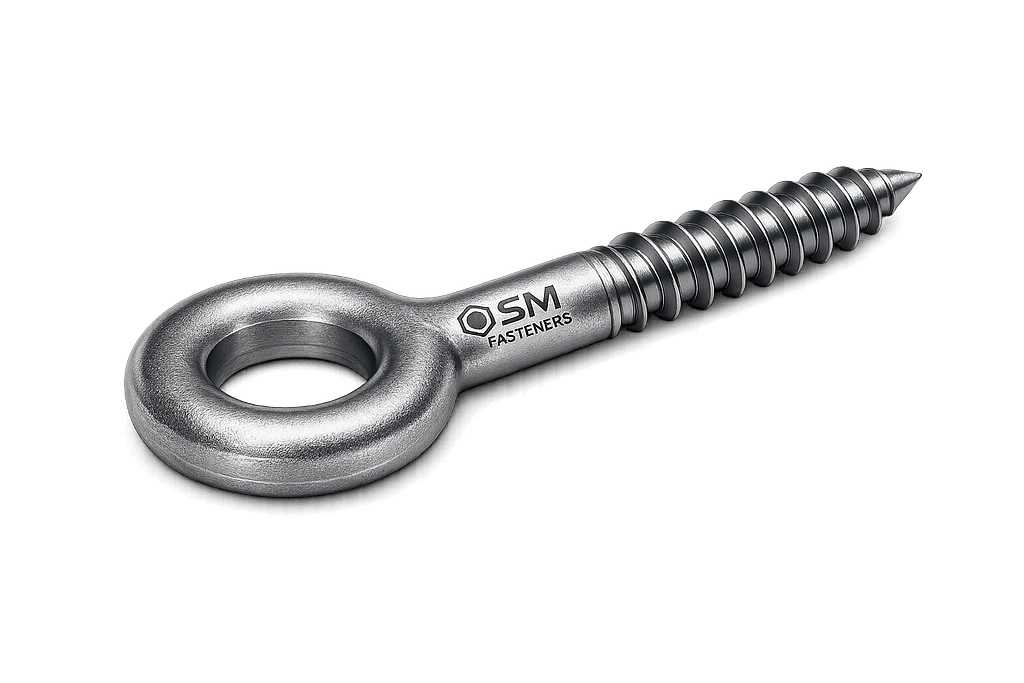
Eye Lag Bolts represent a specialized load-attachment fastener category designed for:
- Structural suspension
- Lifting restraint systems
- Cable anchoring
- Safety tie-off points
- Mechanical retention assemblies
Unlike conventional bolts that clamp components together, the primary function of an Eye Lag Bolt is:
To transfer tensile or angular loads from a connected component into a structural substrate.
The fastener combines:
- Lag screw anchorage principles
- Integrated forged lifting eye geometry
- Threaded wood or masonry engagement
They are widely used where direct anchoring without nut access is required.
1.2 Industrial Usage Environment
Eye Lag Bolts are routinely specified in:
| Industry Sector | Functional Purpose |
|---|---|
| Structural Steel & Construction | Cable support, signage suspension |
| Oil & Gas | Instrument lines, hose restraint |
| Power Generation | Cable trays, lighting supports |
| Petrochemical Plants | Pipe hanger systems |
| LNG & Offshore | Secondary retention anchoring |
| Railways & Infrastructure | Overhead equipment support |
| Shipbuilding | Deck rigging points |
| Heavy Equipment | Temporary lifting anchorage |
Engineers select Eye Lag Bolts where installation accessibility is limited but reliable anchorage is mandatory.
1.3 Functional Difference from Similar Fasteners
| Fastener Type | Load Function | Key Difference |
|---|---|---|
| Eye Bolt | Through-bolt lifting | Requires nut |
| Shoulder Eye Bolt | Precision lifting | Machined seating required |
| J Bolt | Embedded anchorage | Cast-in installation |
| Expansion Anchor | Concrete fixation | Expansion mechanism |
| Eye Lag Bolt | Direct substrate anchoring | Self-threading anchorage |
Eye Lag Bolts eliminate:
- Back-side access requirements
- Through-hole drilling
- Additional hardware components
1.4 Procurement Perspective in EPC Projects
EPC procurement teams evaluate Eye Lag Bolts based on:
- Load rating verification
- Material traceability
- Corrosion performance
- Thread standard compatibility
- Inspection certification availability
As an ISO 9001–controlled manufacturer, SM Fasteners integrates:
- Material traceability
- Batch control
- Mechanical verification
- EN 10204 documentation readiness
ensuring suitability for audited projects.
2. Technical Definition
2.1 Engineering Definition
An Eye Lag Bolt is defined as:
A forged or machined fastener incorporating an integral circular eye and external lag screw threads intended for anchoring into wood, concrete inserts, or engineered structural substrates to support tensile or angular loads.
2.2 Basic Components
| Component | Engineering Function |
|---|---|
| Eye Loop | Load transfer interface |
| Shoulder Transition | Stress distribution zone |
| Shank | Structural load path |
| Lag Thread | Substrate engagement |
| Tip | Installation penetration |
2.3 Geometry Characteristics
Key geometric parameters influencing performance:
- Eye internal diameter
- Eye cross-section thickness
- Shank diameter
- Thread depth
- Embedded thread length
- Root radius transition
Proper geometry prevents:
- Stress concentration
- Eye deformation
- Thread stripping failure
2.4 Typical Installation Substrates
- Timber beams
- Laminated structural wood
- Concrete (with inserts)
- Steel via tapped bosses
- Composite industrial structures
2.5 Load Classification
Eye Lag Bolts primarily experience:
- Axial tension
- Angular tension
- Cyclic loading
- Dynamic vibration forces
They are not intended for high bending loads unless specifically engineered.
3. Load Mechanics & Force Behavior
3.1 Load Transfer Mechanism
Load transfer occurs through three sequential paths:
- Load enters eye
- Force travels through shank
- Thread shear transfers load to substrate
Load → Eye → Shank → Thread Engagement → Base Material3.2 Primary Load Types
| Load Type | Behavior |
|---|---|
| Pure Tension | Ideal loading condition |
| Angular Load | Reduced capacity |
| Shear | Secondary resistance |
| Dynamic Load | Fatigue governing |
| Shock Load | Requires safety factor |
3.3 Tensile Force Mechanics
Ultimate performance depends on:
- Thread engagement depth
- Material yield strength
- Substrate density
- Installation torque
Tensile capacity:
Where:
- = tensile stress area
- = yield strength
3.4 Thread Anchorage Mechanics
Lag threads develop holding strength through:
- Thread flank bearing
- Wood or insert compression
- Frictional resistance
Failure modes:
- Pull-out failure
- Substrate splitting
- Thread stripping
3.5 Effect of Load Angle
Allowable load decreases significantly with angle.
| Load Angle | Capacity Reduction |
|---|---|
| 0° (Vertical) | 100% |
| 30° | ~85% |
| 45° | ~70% |
| 60° | ~50% |
| 90° | Not recommended |
Engineering practice requires:
- Vertical loading whenever possible
- Swivel connectors for angular alignment
3.6 Stress Concentration Zones
Critical stress regions:
- Eye-to-shank transition
- First engaged thread
- Root of thread profile
Forged eyes offer superior fatigue resistance compared to welded eyes.
SM Fasteners manufactures precision-forged configurations minimizing stress risers.
3.7 Friction & Torque–Tension Relationship
Torque applied during installation generates preload:
Where:
- T = Torque
- K = Nut factor
- F = Preload
- D = Diameter
Lag bolts rely partly on:
- Thread cutting resistance
- Frictional compression
3.8 Preload Behavior
Proper preload ensures:
- Reduced micro-movement
- Improved fatigue resistance
- Stable load transfer
Under-tightening → loosening
Over-tightening → substrate failure
4. Joint Design Principles
4.1 Engineering Design Objectives
Joint design using Eye Lag Bolts must achieve:
- Secure anchorage
- Controlled load direction
- Long-term fatigue resistance
- Corrosion durability
4.2 Minimum Thread Engagement
Recommended engagement:
| Substrate | Minimum Engagement |
|---|---|
| Softwood | 8 × diameter |
| Hardwood | 6 × diameter |
| Steel insert | 1.5 × diameter |
| Concrete insert | Manufacturer rating |
4.3 Edge Distance Requirements
Improper placement causes substrate cracking.
| Parameter | Recommended Minimum |
|---|---|
| Edge distance | 4 × diameter |
| Spacing between bolts | 6 × diameter |
| End distance | 7 × diameter |
4.4 Design Safety Factors
Industrial standards typically apply:
| Application | Safety Factor |
|---|---|
| Static load | 3:1 |
| Dynamic load | 5:1 |
| Lifting applications | 6:1 minimum |
4.5 Thread Engagement Efficiency
Effective load capacity depends on:
- Thread depth
- Pitch geometry
- Substrate modulus
Full capacity achieved only when:
4.6 Failure Mechanisms in Service
1. Fatigue Failure
Caused by cyclic loading at eye transition.
2. Shear Failure
Occurs when load applied laterally.
3. Hydrogen Embrittlement
Risk in high-strength electroplated fasteners.
4. Stress Corrosion Cracking
Observed in chloride or H₂S environments.
SM Fasteners controls these risks via:
- Material selection
- Heat treatment control
- Certified coating processes
4.7 Installation Engineering Considerations
Engineers must verify:
- Correct pilot hole diameter
- Alignment during tightening
- Torque monitoring
- Substrate integrity
Incorrect installation accounts for the majority of field failures.
4.8 Compatibility with Advanced Materials (Including PEEK Systems)
In chemical or electrical isolation applications:
- PEEK washers
- PEEK spacers
- Hybrid metal-PEEK assemblies
may be integrated with Eye Lag Bolts supplied by SM Fasteners for:
Cryogenic stability
Electrical insulation
Chemical resistance
Weight reduction
5. Product Types and Variants
Eye Lag Bolts are produced in multiple engineered configurations to meet load orientation, installation conditions, and environmental exposure requirements.
Unlike standardized hex bolts, Eye Lag Bolts combine anchoring mechanics with load attachment geometry, resulting in several functional variants.
5.1 Classification by Eye Geometry
5.1.1 Standard Round Eye Lag Bolt
- Circular forged eye
- General suspension applications
- Accepts hooks, shackles, chains
Typical Uses
- Cable support
- Light mechanical suspension
- Structural tie-offs
5.1.2 Heavy Pattern Forged Eye Lag Bolt
- Increased eye cross-section
- Improved fatigue resistance
- Higher shock load tolerance
Used in:
- Oil & gas facilities
- Offshore structures
- Power plants
5.1.3 Long Shank Eye Lag Bolt
- Extended unthreaded section
- Allows standoff mounting
Applications:
- Pipe hangers
- Cable trays
- Insulated panels
5.1.4 Closed Safety Eye Design
- Reduced eye opening tolerance
- Prevents accidental disengagement
Common in:
- Safety restraint systems
- Rail infrastructure
- Temporary lifting restraints
5.1.5 Welded Eye Lag Bolt (Special Fabrication)
Used only when forging constraints exist.
⚠ Engineering Note:
Welded eyes exhibit reduced fatigue life compared to forged configurations and require additional NDT inspection.
SM Fasteners prioritizes precision forging to maintain grain continuity and eliminate weld defects.
5.2 Classification by Thread Type
| Thread Type | Application |
|---|---|
| Coarse Lag Thread | Timber anchorage |
| Deep Wood Thread | Softwood applications |
| Machine Thread | Steel inserts |
| Dual Thread | Hybrid installations |
| Self-tapping Lag | Composite panels |
5.3 Classification by Installation Method
| Type | Installation Method |
|---|---|
| Manual Installation | Wrench through eye |
| Rod Assisted Installation | Steel bar used for leverage |
| Pre-installed Insert Type | Concrete anchor systems |
| Chemical Anchor Compatible | Resin bonded inserts |
5.4 Custom Engineered Variants (SM Fasteners Capability)
SM Fasteners manufactures project-specific designs including:
- Oversized lifting eyes
- Offshore corrosion-resistant variants
- High-temperature eye lag bolts
- Cryogenic-service fasteners
- PEEK-integrated insulated assemblies
Custom engineering includes:
- Load validation
- Finite element geometry optimization
- Drawing approval before production
6. Dimensional Logic and Geometry
Eye Lag Bolt performance depends strongly on dimensional relationships rather than diameter alone.
6.1 Primary Dimensional Parameters
| Symbol | Description |
|---|---|
| d | Nominal shank diameter |
| L | Overall length |
| Le | Thread engagement length |
| Di | Eye internal diameter |
| Do | Eye outer diameter |
| t | Eye thickness |
| P | Thread pitch |
6.2 Engineering Dimensional Principles
Eye Diameter Selection
Must allow free articulation without side loading.
Recommended:
Eye Thickness Requirement
Eye thickness governs fatigue life.
Thread Engagement Rule
6.3 Standard Dimensional Specification Table
(Typical SM Fasteners Production Range)
| Size | Thread Pitch | Overall Length (mm) | Thread Length (mm) | Eye ID (mm) | Eye OD (mm) | Eye Thickness (mm) |
|---|---|---|---|---|---|---|
| M6 | 1.0 | 60–120 | 40 | 12 | 20 | 4 |
| M8 | 1.25 | 80–160 | 50 | 16 | 26 | 5 |
| M10 | 1.5 | 100–200 | 65 | 20 | 32 | 6 |
| M12 | 1.75 | 120–250 | 80 | 24 | 38 | 7 |
| M16 | 2.0 | 160–300 | 100 | 30 | 48 | 9 |
| M20 | 2.5 | 200–400 | 130 | 38 | 60 | 12 |
| M24 | 3.0 | 250–450 | 150 | 45 | 72 | 14 |
| M30 | 3.5 | 300–600 | 180 | 55 | 88 | 18 |
(All dimensions configurable per project drawings.)
6.4 Weight Chart — SM Fasteners Reference
| Size | Weight / Piece (kg) | Weight / 100 pcs (kg) |
|---|---|---|
| M6 | 0.03 | 3 |
| M8 | 0.06 | 6 |
| M10 | 0.10 | 10 |
| M12 | 0.18 | 18 |
| M16 | 0.35 | 35 |
| M20 | 0.70 | 70 |
| M24 | 1.20 | 120 |
| M30 | 2.30 | 230 |
Used by EPC buyers for logistics planning and freight estimation.
7. Applicable International Standards
Eye Lag Bolts combine requirements from multiple standards since no single universal standard fully defines them.
7.1 ISO Standards
| Standard | Scope |
|---|---|
| ISO 898-1 | Mechanical properties of steel fasteners |
| ISO 3506 | Stainless steel fasteners |
| ISO 965 | Thread tolerances |
| ISO 3269 | Acceptance inspection |
| ISO 4759 | Dimensional tolerances |
7.2 ASTM Standards
| Standard | Application |
|---|---|
| ASTM A307 | Carbon steel bolts |
| ASTM A193 | High-temperature alloy fasteners |
| ASTM A320 | Low-temperature service |
| ASTM F593 | Stainless steel bolts |
| ASTM B574 | Nickel alloy fasteners |
7.3 DIN Standards (Common References)
| DIN Standard | Description |
|---|---|
| DIN 580 | Lifting eye bolts (reference geometry) |
| DIN 7990 | Structural bolting |
| DIN 267 | Fastener technical delivery conditions |
7.4 British Standards (BS)
| BS Standard | Description |
|---|---|
| BS 3692 | ISO metric bolts |
| BS 4190 | Metric bolt dimensions |
| BS EN 14399 | High-strength structural fasteners |
7.5 Thread Standards & Tolerances Table
| Thread System | Designation | Typical Tolerance |
|---|---|---|
| Metric Coarse | M | 6g / 6H |
| UNC | Unified Coarse | 2A / 2B |
| UNF | Unified Fine | 2A / 2B |
| BSW | Whitworth | Medium fit |
| BSF | Fine Whitworth | Close fit |
SM Fasteners supplies all global thread systems to ensure interchangeability across international projects.
8. Mechanical Properties — Grade Wise
8.1 Carbon & Alloy Steel Property Classes
| Property Class | Yield Strength (MPa) | Tensile Strength (MPa) | Typical Application |
|---|---|---|---|
| 4.6 | 240 | 400 | Light structural |
| 5.8 | 400 | 500 | General anchorage |
| 8.8 | 640 | 800 | Structural duty |
| 10.9 | 940 | 1040 | Heavy industrial |
| 12.9 | 1100 | 1220 | High-load engineering |
8.2 Stainless Steel Grades
| Grade | UTS (MPa) | Corrosion Resistance | Environment |
|---|---|---|---|
| A2-70 | 700 | Excellent | Outdoor |
| A4-70 | 700 | Marine resistant | Offshore |
| A4-80 | 800 | Superior | Chemical plants |
9. Proof Load & Tensile Strength Table
| Size | Stress Area (mm²) | Proof Load 8.8 (kN) | Ultimate Load (kN) |
|---|---|---|---|
| M8 | 36.6 | 23 | 29 |
| M10 | 58 | 37 | 47 |
| M12 | 84.3 | 54 | 67 |
| M16 | 157 | 100 | 125 |
| M20 | 245 | 157 | 196 |
| M24 | 353 | 226 | 283 |
| M30 | 561 | 359 | 449 |
Values depend on material grade and substrate capacity.
10. Engineering Interchangeability Considerations
Procurement teams must verify:
- Thread compatibility
- Eye geometry clearance
- Load rating equivalence
- Certification traceability
Interchangeability risks arise when:
- Metric bolts replace UNC threads
- Forged eyes substituted with welded eyes
- Material grade downgraded without approval
SM Fasteners ensures project compliance through:
- Drawing-controlled manufacturing
- Batch traceability
- Material verification aligned with ISO 9001 quality systems.
11. Material Grades and Selection Criteria
Material selection for Eye Lag Bolts directly determines:
- Load carrying capacity
- Corrosion resistance
- Temperature capability
- Fatigue life
- Compliance with oil & gas specifications
Engineering selection must consider mechanical loading + environmental exposure simultaneously.
11.1 Carbon Steel Fasteners
Typical Grades
- ASTM A307
- IS 1367
- Property Class 4.6 / 5.8 / 8.8
Characteristics
- High strength-to-cost ratio
- Suitable for indoor structural anchoring
- Requires protective coating
Applications
- Structural steel frameworks
- Industrial buildings
- Cable suspension systems
11.2 Alloy Steel Eye Lag Bolts
Typical Materials:
- ASTM A193 B7
- AISI 4140 / 4340
- Property Class 10.9 / 12.9
Advantages
- High tensile strength
- Superior fatigue resistance
- Elevated temperature capability
Used in:
- Power plants
- Petrochemical facilities
- Heavy machinery anchorage
11.3 Stainless Steel Grades
| Grade | Equivalent | Key Advantage |
|---|---|---|
| SS304 | A2 | General corrosion resistance |
| SS316 | A4 | Marine & chloride resistance |
| SS316L | Low carbon | Weld decay resistance |
| Duplex 2205 | UNS S32205 | High strength + corrosion resistance |
| Super Duplex 2507 | UNS S32750 | Offshore & seawater service |
11.4 Nickel Alloy & Exotic Materials
SM Fasteners supplies advanced alloys for critical projects:
- Hastelloy C276
- Inconel 625 / 718
- Incoloy 825
- Monel 400
- Nickel 200/201
- SMO 254
These materials resist:
- Chloride stress corrosion cracking
- Sour gas exposure
- Acidic chemical environments
- High temperature oxidation
11.5 PEEK Fastener Integration
For specialized assemblies, Eye Lag Bolts may incorporate:
- PEEK bushings
- PEEK washers
- Hybrid metal-polymer isolation systems
Benefits:
- Electrical insulation
- Chemical inertness
- Cryogenic compatibility
- Weight reduction
Used in:
- LNG systems
- Electrical installations
- Semiconductor plants
- Chemical processing equipment
11.6 Material Selection Matrix
| Environment | Recommended Material |
|---|---|
| Indoor dry | Carbon steel 8.8 |
| Outdoor industrial | SS304 / coated steel |
| Marine offshore | SS316 / Duplex |
| Chemical plant | Hastelloy / SMO 254 |
| Sour service (H₂S) | NACE compliant alloy |
| High temperature | Inconel |
| Cryogenic | Austenitic stainless |
12. Mechanical Properties — Material Comparison Table
| Material | UTS (MPa) | Yield (MPa) | Temp Limit | Corrosion Resistance | Relative Cost | Typical Industry |
|---|---|---|---|---|---|---|
| Carbon Steel | 400–800 | 240–640 | 300°C | Low | Low | Construction |
| Alloy Steel | 900–1200 | 800+ | 450°C | Moderate | Medium | Power/Oil |
| SS304 | ~700 | ~450 | 870°C | High | Medium | Infrastructure |
| SS316 | ~700 | ~450 | 900°C | Very High | Medium-High | Offshore |
| Duplex | 800–900 | 550 | 300°C | Excellent | High | Marine |
| SMO 254 | 650 | 300 | 400°C | Extreme | Very High | Chemical |
| Inconel 625 | 900 | 450 | 1000°C | Extreme | Premium | Aerospace/LNG |
| PEEK | — | — | 260°C | Chemical inert | High | Electrical |
13. Heat Treatment Processes
Heat treatment controls final mechanical performance.
13.1 Heat Treatment Objectives
- Increase strength
- Improve toughness
- Control hardness
- Reduce residual stress
- Enhance fatigue resistance
13.2 Standard Heat Treatment Routes
Quenching & Tempering
Used for grades 8.8, 10.9, 12.9.
Process:
- Austenitizing
- Oil quenching
- Controlled tempering
Result:
- High strength
- Stable microstructure
Solution Annealing (Stainless Steel)
Applied to:
- SS304
- SS316
- Duplex alloys
Benefits:
- Restores corrosion resistance
- Eliminates carbide precipitation
Age Hardening (Nickel Alloys)
Used for:
- Inconel 718
- Precipitation-strengthened alloys
Improves:
- High-temperature strength
- Creep resistance
13.3 Hardness Control (Critical Requirement)
| Grade | Hardness Range |
|---|---|
| 8.8 | 22–32 HRC |
| 10.9 | 32–39 HRC |
| 12.9 | 39–44 HRC |
| Stainless | ≤ 300 HV |
Sour Service Requirement
(NACE MR0175 / ISO 15156)
Maximum hardness typically:
to prevent sulfide stress cracking.
SM Fasteners provides controlled heat treatment with certified hardness verification.
14. End-to-End Manufacturing Workflow
Eye Lag Bolts require a combination of forging accuracy and thread precision.
14.1 Raw Material Verification
Incoming inspection includes:
- Mill Test Certificate (MTC)
- Heat number verification
- Chemical composition analysis
- PMI testing (when required)
14.2 Manufacturing Flow
Raw Material → Cutting → Forging → Eye Formation
→ Normalizing → Machining → Thread Rolling
→ Heat Treatment → Surface Finish → Inspection → Packaging
14.3 Forging vs Machining
| Method | Advantage |
|---|---|
| Hot Forging | Grain flow continuity |
| Closed Die Forging | High fatigue resistance |
| CNC Machining | Precision custom geometry |
Forged eyes are strongly preferred for load-bearing applications.
14.4 Eye Formation Process
Critical manufacturing step:
- Upset forging
- Controlled bending
- Radius forming
Engineering objective:
Eliminate weld joints and micro-cracks.
14.5 Thread Manufacturing
Thread Rolling (Preferred)
Benefits:
- Increased fatigue strength
- Compressive surface stress
- Better dimensional accuracy
Thread Cutting
Used only for:
- Large diameters
- Exotic alloys
14.6 Traceability System
ISO 9001 manufacturing control includes:
- Batch identification
- Heat number stamping
- Production traveler records
- Inspection checkpoints
15. Surface Finishing & Coatings
Surface engineering determines service life.
15.1 Coating Types
| Coating | Thickness | Corrosion Resistance | Application |
|---|---|---|---|
| Black Oxide | Minimal | Low | Indoor |
| Zinc Plated | 5–12 µm | Moderate | General industry |
| Hot Dip Galvanized | 70–100 µm | High | Construction |
| Mechanical Galvanized | Uniform | High | Structural |
| PTFE / Xylan | Low friction | Excellent | Chemical plants |
| Dacromet / Geomet | Non-electrolytic | Very High | Offshore |
| Passivation | Chemical film | Stainless protection | Marine |
| Nickel Plating | Decorative + corrosion | Moderate | Equipment |
15.2 Surface Finish Performance Comparison
| Finish | Salt Spray Resistance | Hydrogen Embrittlement Risk | Temperature Limit |
|---|---|---|---|
| Zinc Electroplate | 96–240 hr | High | 120°C |
| HDG | 720+ hr | Low | 300°C |
| Dacromet | 1000+ hr | Very Low | 300°C |
| PTFE | Excellent | None | 260°C |
| Passivated SS | Excellent | None | 800°C |
15.3 Hydrogen Embrittlement Control
Critical for high-strength Eye Lag Bolts.
Preventive measures:
- Non-electrolytic coatings
- Post-bake treatment
- Hardness control
- Process validation
SM Fasteners applies controlled coating procedures aligned with ISO quality systems.
15.4 Surface Engineering Selection Guide
| Environment | Recommended Finish |
|---|---|
| Indoor | Zinc plated |
| Outdoor | HDG |
| Marine | SS316 / Duplex |
| Offshore | Dacromet / Geomet |
| Chemical | PTFE coated |
| High temperature | Passivated stainless |
16. Inspection & Quality Control
Eye Lag Bolts used in industrial projects must comply with auditable quality assurance systems.
Failure typically originates from inadequate inspection rather than material deficiency.
SM Fasteners integrates inspection controls aligned with ISO 9001 quality management systems ensuring complete traceability.
16.1 Inspection Philosophy
Quality verification follows three stages:
- Incoming Material Inspection
- In-Process Manufacturing Control
- Final Release Inspection
16.2 Dimensional Inspection
Measured parameters include:
- Eye internal diameter
- Eye concentricity
- Shank diameter
- Thread pitch & form
- Thread length
- Overall length
- Surface integrity
Inspection Equipment
- Vernier & digital micrometers
- Thread plug gauges
- Optical comparators
- Profile projectors
- Coordinate measuring machines (CMM)
16.3 Mechanical Testing
| Test | Standard Reference | Purpose |
|---|---|---|
| Tensile Test | ISO 898 / ASTM A370 | Strength verification |
| Proof Load Test | ISO 898 | Elastic limit validation |
| Hardness Test | ISO 6508 | Heat treatment confirmation |
| Bend Test | Internal procedure | Eye integrity |
| Load Simulation | Project specific | Functional verification |
16.4 Non-Destructive Testing (NDT)
Critical for forged lifting components.
| Method | Application |
|---|---|
| Magnetic Particle Inspection (MPI) | Surface cracks |
| Dye Penetrant Testing (PT) | Eye transition defects |
| Ultrasonic Testing (UT) | Internal discontinuities |
| Radiography | Special critical orders |
Forged eyes undergo focused inspection at stress concentration zones.
16.5 Positive Material Identification (PMI)
Required for:
- Duplex
- Super Duplex
- Nickel alloys
- Sour service applications
PMI verifies alloy chemistry against MTC data.
16.6 Documentation & Certification
SM Fasteners supplies full EPC documentation:
| Document | Standard |
|---|---|
| Mill Test Certificate | EN 10204 3.1 |
| Third Party Certification | EN 10204 3.2 |
| Heat Treatment Report | Mandatory |
| Dimensional Inspection Report | Included |
| Coating Thickness Report | Included |
| Certificate of Conformity | Provided |
| NDT Reports | When specified |
17. Failure Mechanisms & Engineering Risk Control
17.1 Fatigue Failure
Causes:
- Cyclic loading
- Improper eye geometry
- Surface defects
Control:
- Forged eye design
- Rolled threads
- Correct preload
17.2 Shear Failure
Occurs when side loading replaces axial loading.
Engineering rule:
Eye Lag Bolts are primarily tension devices.
17.3 Hydrogen Embrittlement
Risk Factors:
- Electroplating
- High hardness steels (>39 HRC)
Mitigation:
- Baking procedures
- Controlled plating
- Alternative coatings
17.4 Stress Corrosion Cracking
Common in:
- Chloride environments
- H₂S service
Mitigation:
- Duplex or nickel alloy materials
- NACE MR0175 compliance
18. Industry Applications
Eye Lag Bolts supplied by SM Fasteners serve critical roles across global industries.
18.1 Construction & Structural Steel
- Suspended services
- Cable routing
- Temporary structural restraint
- Signage anchoring
18.2 Oil & Gas (Upstream–Midstream–Downstream)
Applications include:
- Hose restraint anchorage
- Instrument support
- Secondary lifting restraint
- Safety cable installations
Materials:
- A193 B7
- SS316
- Duplex 2205
- NACE compliant alloys
18.3 Power Generation
- Turbine hall cable suspension
- Lighting systems
- HVAC support anchoring
High-temperature alloys supplied where required.
18.4 Petrochemical & Chemical Processing
Requirements:
- Chemical resistance
- Anti-galling threads
- Corrosion-resistant coatings
Typical materials:
- Hastelloy
- SMO 254
- PTFE-coated assemblies
18.5 LNG & Offshore Installations
Engineering priorities:
- Seawater corrosion resistance
- Low-temperature toughness
- Fatigue resistance
Recommended materials:
- Super Duplex
- Inconel
- A4 stainless steel
18.6 Railways & Infrastructure
- Overhead cable systems
- Bridge service supports
- Signaling equipment anchorage
18.7 Shipbuilding & Marine Engineering
- Deck equipment restraint
- Safety tethering
- Rigging systems
18.8 Automotive & Heavy Equipment Manufacturing
- Transport securing points
- Maintenance lifting anchors
- Assembly retention fixtures
18.9 PEEK Fastener Applications
Where metal isolation is required:
- Electrical switchgear
- Semiconductor manufacturing
- Chemical reactors
- Cryogenic LNG equipment
SM Fasteners integrates PEEK fastener components with metallic Eye Lag Bolt assemblies.
19. Export Capability & Global Supply Readiness
SM Fasteners supports international EPC procurement programs.
19.1 Industrial Packaging
Standard packaging methods:
- VCI corrosion protection
- Thread caps & protectors
- Batch identification labels
- Moisture barrier packaging
19.2 Export Crating
- ISPM-15 compliant wooden crates
- Vacuum sealing (marine shipment)
- Palletized bulk export packing
19.3 Logistics Documentation
Provided with shipment:
- Packing list
- Commercial invoice
- Certificate of Origin
- Inspection release note
- Material traceability documents
19.4 Global Procurement Advantages
SM Fasteners supports:
- Custom drawings
- Low & high volume production
- Project-based manufacturing
- Multi-material capability
- Rapid export coordination
20. Tightening Torque Chart
(Typical reference values — lubricated condition, property class 8.8)
| Size | Torque (Nm) Dry | Torque (Nm) Lubricated |
|---|---|---|
| M8 | 25 | 18 |
| M10 | 49 | 34 |
| M12 | 86 | 60 |
| M16 | 210 | 150 |
| M20 | 410 | 290 |
| M24 | 710 | 500 |
| M30 | 1420 | 1000 |
Actual torque must consider substrate strength.
21. Preload Calculation
Formula
Where:
- F = Preload force
- T = Applied torque
- K = Nut factor (≈0.18 lubricated)
- D = Nominal diameter
Worked Example
Given:
- Bolt Size: M16
- Torque = 150 Nm
- Nut Factor = 0.18
- Diameter = 0.016 m
Approximate preload = 52 kN
22. Corrosion Resistance vs Environment
| Environment | Recommended Material | Coating |
|---|---|---|
| Indoor Dry | Carbon Steel | Zinc |
| Outdoor Industrial | SS304 | Passivation |
| Marine Atmosphere | SS316 | Passivation |
| Offshore Splash Zone | Duplex | Dacromet |
| Acidic Chemical | Hastelloy | PTFE |
| Sour Gas H₂S | NACE Alloy | Controlled hardness |
| Cryogenic | Austenitic SS | None required |
23. Surface Finish Performance Comparison
| Finish | Corrosion Resistance | Maintenance | Typical Use |
|---|---|---|---|
| Zinc Plating | Moderate | Medium | General |
| Hot Dip Galvanized | High | Low | Structural |
| PTFE | Very High | Low | Chemical |
| Dacromet | Extreme | Low | Offshore |
| Passivated Stainless | Excellent | Minimal | Marine |
24. Thread Standards & Tolerances
| Thread | Standard | Fit |
|---|---|---|
| Metric | ISO 965 | 6g |
| UNC | ASME B1.1 | 2A |
| UNF | ASME B1.1 | 2A |
| BSW | BS 84 | Medium |
| BSF | BS 84 | Close |
SM Fasteners supplies interchangeable threading for multinational EPC projects.
25. Engineering Weight Reference Table
(Aligned with SM Fasteners manufacturing data)
| Size | Weight / Piece (kg) | Weight / 100 pcs (kg) |
|---|---|---|
| M6 | 0.03 | 3 |
| M8 | 0.06 | 6 |
| M10 | 0.10 | 10 |
| M12 | 0.18 | 18 |
| M16 | 0.35 | 35 |
| M20 | 0.70 | 70 |
| M24 | 1.20 | 120 |
| M30 | 2.30 | 230 |
Used for freight calculation and structural dead-load analysis.
26. Engineering Selection Checklist (Procurement Ready)
✔ Verify load direction
✔ Confirm material grade
✔ Check corrosion environment
✔ Validate standards compliance
✔ Confirm thread compatibility
✔ Review inspection documentation
✔ Ensure traceability certification
✔ Confirm coating suitability
27. Integrated Manufacturing & Quality Positioning
Through certified manufacturing and engineering control,
SM Fasteners demonstrates capability across:
- Precision forging
- Advanced materials engineering
- Controlled heat treatment
- Certified inspection systems
- Global export compliance
Supporting industries including:
- Construction
- Oil & Gas
- Power Generation
- Petrochemical
- Offshore & LNG
- Infrastructure
- Heavy Engineering OEMs
End of Engineering Reference — Eye Lag Bolt
This four-part document establishes SM Fasteners as a:
- Standards-compliant manufacturer
- Engineering-driven fastener supplier
- Globally reliable EPC procurement partner
- Advanced materials and custom fastener specialist