

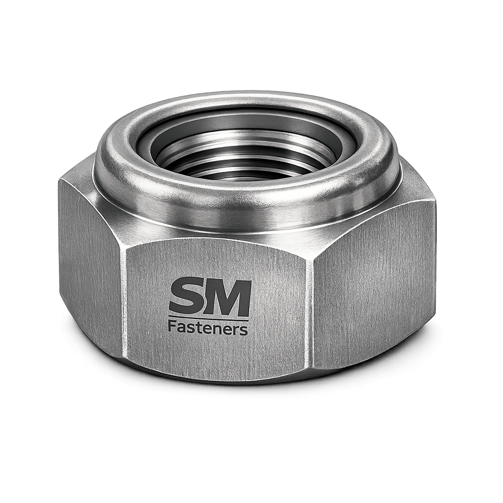
All Metal Lock Nut
1. Industrial Context of All Metal Lock Nuts
Threaded fastening systems remain the primary mechanical joining method across heavy engineering industries due to:
- High load-bearing capability
- Maintainability of assemblies
- Predictable preload behavior
- Compatibility with global standards
However, conventional nuts are susceptible to self-loosening under:
- Dynamic vibration
- Thermal cycling
- Rotational loading
- Shock and impact forces
- Differential expansion between materials
Industries such as Oil & Gas, LNG, Power Generation, Rail Infrastructure, Heavy Equipment, Offshore Platforms, and Structural Steel Construction require fastening systems that maintain clamp load without reliance on polymers or secondary locking devices.
The All Metal Lock Nut was developed to address these reliability requirements.
Unlike nylon insert lock nuts, all metal locking designs retain performance under:
- Elevated temperature environments (>300°C)
- Chemical exposure
- Radiation zones
- Fire-safe applications
- Cryogenic service
SM Fasteners manufactures precision all metal lock nuts engineered for critical load retention, supporting global EPC procurement and inspection requirements.
2. Technical Definition
An All Metal Lock Nut is a threaded fastener incorporating a metallic prevailing torque locking feature, eliminating reliance on plastic inserts or external locking mechanisms.
Locking action is achieved through controlled elastic deformation of the nut body.
Core Functional Principle
The locking mechanism produces:
- Prevailing torque resistance during installation
- Continuous frictional resistance after tightening
- Resistance to vibration-induced rotation
Common locking mechanisms include:
- Top-lock deformation
- Elliptical distortion
- Slotted crown deformation
- Beam-style locking sections
- Conical interference threads
3. Functional Role in Bolted Assemblies
An all metal lock nut performs two simultaneous engineering functions:
- Primary Clamp Load Generation
- Secondary Anti-Rotation Locking
Mechanical Objectives
| Function | Engineering Purpose |
|---|---|
| Preload generation | Creates clamping force |
| Friction stabilization | Prevents loosening |
| Vibration resistance | Maintains joint integrity |
| Thermal reliability | No polymer degradation |
| Reusability | Maintains locking torque |
4. Load Mechanics & Force Behavior
4.1 Bolt–Nut Load System
When torque is applied:
- Threads convert torque into axial force.
- Bolt elongates elastically.
- Joint members compress.
- Clamp load develops.
The assembly behaves like two springs:
- Bolt → tension spring
- Joint → compression spring
Stable preload ensures external forces are absorbed without joint separation.
4.2 Preload Fundamentals
Preload is the single most important parameter in fastener performance.
Where:
- = Preload force (N)
- = Applied torque (Nm)
- = Nut factor
- = Nominal diameter (m)
Typical nut factor values:
| Condition | Nut Factor (K) |
|---|---|
| Dry | 0.20–0.25 |
| Zinc coated | 0.18–0.22 |
| Lubricated | 0.12–0.16 |
| PTFE coated | 0.10–0.14 |
All metal lock nuts introduce prevailing torque, meaning additional torque is required beyond seating torque.
4.3 Prevailing Torque Concept
Prevailing torque = Torque required to rotate the nut without clamp load.
Engineering significance:
- Maintains resistance against loosening
- Independent of clamp force
- Remains effective after load relaxation
4.4 Force Behavior Under Dynamic Loading
Industrial joints experience:
- Transverse vibration
- Axial cyclic loading
- Thermal expansion
- Shock impulses
Self-loosening occurs when transverse displacement reduces friction below rotation resistance.
All metal lock nuts counteract this through:
- Radial thread interference
- Elastic recovery forces
- Continuous contact pressure
5. Joint Design Principles
5.1 Joint Categories
| Joint Type | Lock Nut Requirement |
|---|---|
| Static structural | Optional |
| Vibratory machinery | Mandatory |
| Rotating equipment | Mandatory |
| High temperature | Essential |
| Offshore assemblies | Recommended |
| Pressure equipment | Critical |
5.2 Recommended Design Rules
Thread Engagement
Minimum engagement:
- Steel → 1 × diameter
- Stainless → 1.5 × diameter
- Aluminum → 2 × diameter
Typical engineering practice:
Clamp Load Target
Ensures:
- Maximum fatigue resistance
- No yielding during service
5.3 Friction Zones in Threaded Assemblies
Torque distribution:
| Location | Torque Consumption |
|---|---|
| Thread friction | 40–50% |
| Bearing surface | 40–50% |
| Bolt stretch | 10–15% |
This explains why surface finish and lubrication strongly influence performance.
6. Torque–Tension Relationship
Torque alone does not guarantee preload.
Variables affecting accuracy:
- Surface roughness
- Coating thickness
- Lubrication condition
- Material hardness mismatch
- Thread tolerance class
All metal lock nuts must be selected considering combined torque + prevailing torque values.
7. Failure Mechanisms Addressed by All Metal Lock Nuts
7.1 Self-Loosening
Primary failure mode in vibration environments.
Mitigated by:
- Metallic locking deformation
- Continuous interference pressure
7.2 Fatigue Failure
Occurs due to fluctuating stress when preload is lost.
All metal lock nuts maintain preload → reduces fatigue crack initiation.
7.3 Thermal Relaxation
High temperature causes:
- Polymer insert degradation
- Loss of locking ability
All metal designs remain stable above 600°C depending on material.
7.4 Hydrogen Embrittlement
Critical for:
- High-strength alloy steel fasteners
- Electroplated components
SM Fasteners applies controlled finishing and baking procedures compliant with international standards.
7.5 Stress Corrosion Cracking
Relevant environments:
- Chlorides
- H₂S service
- Offshore exposure
Material selection aligned with NACE MR0175 / ISO 15156 mitigates risk.
8. Engineering Advantages Over Other Locking Systems
| Locking Method | Temperature Limit | Reusable | Chemical Resistant |
|---|---|---|---|
| nylon insert nut | ~120°C | Limited | Poor |
| Adhesives | Variable | No | Limited |
| Double nut | Moderate | Yes | Moderate |
| All Metal Lock Nut | Very High | Yes | Excellent |
9. Selection Criteria (Engineering Perspective)
Engineers specify all metal lock nuts when:
- Operating temperature exceeds polymer limits
- Inspection accessibility is limited
- Safety-critical joint exists
- Maintenance cycles are long
- Vibration is continuous
10. SM Fasteners Engineering Capability
SM Fasteners integrates:
- ISO 9001 quality management systems
- UKAF accredited manufacturing processes
- MSME certified industrial production capability
Manufacturing includes:
Advanced materials including PEEK fasteners for lightweight chemical-resistant assemblies
Precision cold forging
CNC machining for specialty alloys
Custom locking torque calibration
11. Product Types and Variants of All Metal Lock Nuts
All metal lock nuts are engineered using controlled metallic deformation to generate prevailing torque.
Selection depends on:
- Load class
- Temperature exposure
- Installation frequency
- Space constraints
- Inspection accessibility
- Applicable international standards
SM Fasteners manufactures multiple geometries aligned with global EPC specifications and OEM engineering requirements.
11.1 Top Lock (Stover Type) All Metal Lock Nut
Construction Principle
The top portion of the nut is elliptically deformed during manufacturing.
- Thread axis slightly offset
- Creates radial interference with mating bolt
- Generates consistent prevailing torque
Engineering Characteristics
| Parameter | Description |
|---|---|
| Locking method | Elliptical deformation |
| Temperature capability | Very high |
| Reusability | High |
| Vibration resistance | Excellent |
| Typical industries | Structural, heavy equipment |
11.2 Center Lock All Metal Nut
Locking achieved at the mid-section of threads rather than the top.
Advantages:
- Reduced installation torque variation
- Improved alignment
- Lower galling risk in stainless assemblies
Used in:
- Precision mechanical assemblies
- Automotive powertrain systems
- Rotating machinery
11.3 Slotted / Crown Lock Nut (All Metal)
Locking achieved by:
- Slot deformation
- Metal beam flexure
- Controlled compression
Typical applications:
- Aerospace hardware
- High-cycle vibration systems
- Maintenance-critical assemblies
11.4 Two-Way Reversible Lock Nut
Designed to function from either installation side.
Benefits:
- Reduced installation errors
- Faster field assembly
- Preferred in maintenance-intensive plants
11.5 Heavy Hex All Metal Lock Nut
Increased width across flats provides:
- Higher bearing surface
- Increased preload capability
- Improved wrench engagement
Common in:
- Oil & Gas flanges
- Pressure vessels
- Structural steel connections
11.6 High Temperature All Metal Lock Nut
Manufactured using:
- Alloy steel
- Inconel
- Hastelloy
- SMO 254
- Duplex & Super Duplex grades
Designed for:
- Turbines
- Refineries
- LNG facilities
- Furnace equipment
11.7 Custom Engineered Lock Nuts — SM Fasteners Capability
SM Fasteners supports project-specific manufacturing:
- Non-standard heights
- Fine pitch threads
- Metric–Imperial hybrid compatibility
- Special prevailing torque calibration
- PEEK-based engineered locking solutions for lightweight corrosion-critical assemblies
12. Dimensional Logic and Geometry
The geometry of an all metal lock nut directly influences:
- Load distribution
- Prevailing torque
- Installation repeatability
- Fatigue performance
12.1 Fundamental Nut Geometry Parameters
| Dimension | Symbol | Engineering Role |
|---|---|---|
| Nominal diameter | d | Load capacity |
| Pitch | P | Axial advance |
| Width across flats | s | Tool engagement |
| Nut height | m | Thread engagement |
| Locking zone height | hL | Prevailing torque |
| Bearing face diameter | dw | Load distribution |
12.2 Standard Metric Dimensional Specifications (ISO Pattern)
| Size | Pitch (mm) | Width Across Flats (mm) | Height (mm) | Approx Weight (kg/100 pcs)* |
|---|---|---|---|---|
| M6 | 1.0 | 10 | 6 | 0.35 |
| M8 | 1.25 | 13 | 8 | 0.75 |
| M10 | 1.5 | 17 | 10 | 1.50 |
| M12 | 1.75 | 19 | 12 | 2.70 |
| M16 | 2.0 | 24 | 16 | 6.30 |
| M20 | 2.5 | 30 | 20 | 12.5 |
| M24 | 3.0 | 36 | 24 | 22.0 |
| M30 | 3.5 | 46 | 30 | 48.0 |
| M36 | 4.0 | 55 | 36 | 82.0 |
*Weights aligned with SM Fasteners manufacturing reference data.
12.3 Dimensional Design Logic
Nut Height vs Strength
General rule:
Ensures:
- Full proof load development
- Thread shear resistance
- Fatigue durability
Bearing Surface Requirements
Large bearing faces:
- Reduce embedding loss
- Improve preload retention
- Lower surface pressure
12.4 Thread Engagement Engineering
| Bolt Material | Minimum Engagement |
|---|---|
| Carbon Steel | 1 × diameter |
| Stainless Steel | 1.5 × diameter |
| Aluminum Joint | 2 × diameter |
| High temperature alloys | 1.25 × diameter |
13. Thread Standards & Tolerances
All metal lock nuts must maintain compatibility with internationally interchangeable thread systems.
SM Fasteners manufactures in both metric and imperial standards.
13.1 Thread Standards Comparison
| Thread System | Standard | Flank Angle | Application |
|---|---|---|---|
| Metric | ISO 261 / ISO 965 | 60° | Global industry |
| UNC | ASME B1.1 | 60° | Heavy engineering |
| UNF | ASME B1.1 | 60° | High strength joints |
| BSW | BS 84 | 55° | Legacy equipment |
| BSF | BS 84 | 55° | Fine pitch systems |
13.2 Tolerance Classes
| Class | Fit Type | Application |
|---|---|---|
| 6H | Standard nut | General industrial |
| 5H | Precision fit | Automotive |
| 4H | Close tolerance | Aerospace |
| 2B | UNC/UNF | Standard US fit |
Prevailing torque locking deformation is applied after threading while maintaining tolerance compliance.
14. Applicable International Standards
All metal lock nuts are governed by dimensional, mechanical, and performance standards.
14.1 ISO Standards
| Standard | Scope |
|---|---|
| ISO 7042 | All metal prevailing torque nuts |
| ISO 2320 | Prevailing torque testing |
| ISO 898-2 | Mechanical properties |
| ISO 965 | Thread tolerance system |
| ISO 4032 | Hex nut dimensions |
| ISO 9001 | Quality management system |
14.2 DIN Standards
| Standard | Description |
|---|---|
| DIN 980 | All metal self-locking nuts |
| DIN 982 | Lock nut variants |
| DIN 934 | Hex nuts |
| DIN 267 | Mechanical performance |
14.3 ASTM / ASME Standards
| Standard | Application |
|---|---|
| ASTM A194 | High pressure nut materials |
| ASTM A563 | Carbon steel nuts |
| ASTM F594 | Stainless steel nuts |
| ASME B18.2.2 | Inch series dimensions |
14.4 British Standards
| Standard | Scope |
|---|---|
| BS 3692 | Metric fasteners |
| BS 1083 | High temperature fasteners |
| BS 1768 | Mechanical property requirements |
15. Property Class Systems
Mechanical capability defined by standardized property classes.
15.1 Metric Property Classes
| Property Class | Proof Stress (MPa) | Typical Use |
|---|---|---|
| 8 | 600 | Structural |
| 10 | 830 | Heavy machinery |
| 12 | 970 | High load dynamic |
| A2-70 | Stainless general | |
| A4-80 | Marine / chemical |
15.2 Imperial Grade Equivalence
| Metric | ASTM Equivalent |
|---|---|
| Class 8 | ASTM A563 Grade A |
| Class 10 | ASTM A563 DH |
| Class 12 | ASTM A194 2H |
16. Interchangeability Considerations
Critical procurement factor for EPC buyers.
Engineering Checks
- Thread form compatibility
- Pitch matching
- Property class equivalence
- Coating thickness tolerance
- Prevailing torque compliance
Incorrect interchangeability can cause:
- False torque readings
- Thread seizure
- Reduced preload
- Premature failure
SM Fasteners validates interchangeability through controlled inspection and dimensional verification.
17. Prevailing Torque Performance Requirements (ISO 2320)
Testing ensures locking function consistency.
| Size Range | Minimum Prevailing Torque (Example) |
|---|---|
| M6–M10 | 0.5–3 Nm |
| M12–M16 | 3–10 Nm |
| M20–M24 | 10–30 Nm |
| M30+ | Project specific |
Tests conducted:
- First installation torque
- Removal torque
- Reusability verification
18. Engineering Advantages of Correct Geometry Selection
Proper geometry delivers:
- Stable preload
- Reduced vibration loosening
- Improved fatigue life
- Repeatable installation torque
- Inspection reliability
19. SM Fasteners — Dimensional Manufacturing Capability
SM Fasteners provides:
- ISO compliant production
- CNC-controlled deformation forming
- Automated thread gauging
- Batch traceability
- Custom engineered dimensions
Supported material platforms include:
- Stainless Steel
- Carbon & Alloy Steel
- Duplex / Super Duplex
- Hastelloy
- Inconel / Incoloy
- Monel
- Nickel alloys
- High-performance PEEK fasteners
All dimensional data aligns with global project documentation and third-party inspection expectations.
20. Material Grades and Engineering Selection Criteria
Material selection for All Metal Lock Nuts directly determines:
- Load capacity
- Temperature capability
- Corrosion resistance
- Galling behavior
- Hydrogen embrittlement susceptibility
- Service life under cyclic loading
SM Fasteners manufactures all metal lock nuts across a complete industrial material spectrum aligned with EPC procurement specifications and international standards.
20.1 Primary Material Categories
| Material Group | Typical Grades | Key Characteristics |
|---|---|---|
| Carbon Steel | ASTM A563, ISO Class 8 | Economical structural applications |
| Alloy Steel | ASTM A194 2H, Class 10/12 | High strength, elevated loads |
| Stainless Steel | A2-70, A4-80 | Corrosion resistance |
| Duplex Stainless | UNS S31803 | High strength + chloride resistance |
| Super Duplex | UNS S32750 | Offshore & seawater service |
| Nickel Alloys | Monel 400 | Marine corrosion resistance |
| High Temp Alloys | Inconel 625/718 | Extreme temperature stability |
| Chemical Alloys | Hastelloy C276 | Acid resistance |
| Super Austenitic | SMO 254 | Chloride & pitting resistance |
| Polymer Engineering | PEEK | Lightweight chemical systems |
20.2 Material Selection Logic
Engineers evaluate:
Load Requirement
Higher property classes → alloy steel selection.
Environment
Corrosion exposure dictates stainless or nickel alloys.
Temperature
Polymer locking solutions fail above ~120°C → all metal preferred.
Maintenance Accessibility
Long maintenance intervals demand metallic locking reliability.
20.3 Material Comparison Table
| Material | UTS (MPa) | Yield (MPa) | Corrosion Resistance | Temp Limit | Relative Cost | Typical Industry |
|---|---|---|---|---|---|---|
| Carbon Steel | 800 | 640 | Low | 300°C | Low | Structural |
| Alloy Steel | 1040 | 940 | Moderate | 450°C | Medium | Oil & Gas |
| A2-70 SS | 700 | 450 | Good | 400°C | Medium | General industry |
| A4-80 SS | 800 | 600 | Excellent | 450°C | Higher | Marine |
| Duplex | 850 | 620 | Excellent | 300°C | High | Offshore |
| Super Duplex | 950 | 750 | Extreme | 300°C | Very High | Seawater |
| Inconel 718 | 1250 | 1030 | Exceptional | 700°C+ | Premium | Turbines |
| Hastelloy C276 | 790 | 355 | Acid resistant | 600°C | Premium | Chemical plants |
| SMO 254 | 650 | 300 | Extreme chloride | 300°C | Premium | Desalination |
| PEEK | — | — | Chemical resistant | 250°C | Specialized | Lightweight assemblies |
20.4 Corrosion Resistance vs Environment
| Environment | Recommended Material |
|---|---|
| Atmospheric outdoor | Zinc coated carbon steel |
| Marine atmosphere | A4-80 / Duplex |
| Seawater immersion | Super Duplex / Monel |
| H₂S sour service | NACE compliant alloy steel |
| Acid processing | Hastelloy |
| LNG cryogenic | Austenitic stainless |
| High temperature furnace | Inconel |
| Chemical lightweight systems | PEEK fasteners |
SM Fasteners supports NACE MR0175 / ISO 15156 compliant materials for sour service projects.
21. Mechanical Properties — Grade Wise
| Property Class | Proof Load (MPa) | Hardness Range | Application |
|---|---|---|---|
| Class 8 | 600 | 22–32 HRC | Structural |
| Class 10 | 830 | 26–36 HRC | Heavy machinery |
| Class 12 | 970 | 32–39 HRC | Dynamic loading |
| A2-70 | 450 | HRB 95 max | Corrosion resistant |
| A4-80 | 600 | HRB 95 max | Marine |
| ASTM A194 2H | 850 | 24–35 HRC | Pressure vessels |
Hardness control is critical to prevent:
- Thread stripping
- Galling
- Hydrogen embrittlement
22. Heat Treatment Processes
Heat treatment defines final mechanical performance of all metal lock nuts.
22.1 Heat Treatment Objectives
- Increase strength
- Improve fatigue resistance
- Achieve required hardness
- Stabilize microstructure
- Enable locking deformation without cracking
22.2 Standard Heat Treatment Workflow
1. Austenitizing
Heating steel above transformation temperature.
2. Quenching
Rapid cooling to form martensite.
3. Tempering
Controlled reheating to achieve toughness.
22.3 Typical Heat Treatment Parameters
| Grade | Treatment | Result |
|---|---|---|
| Class 8 | Normalize + temper | Balanced strength |
| Class 10 | Q&T | High tensile |
| Class 12 | Q&T optimized | Maximum strength |
| A194 2H | Heavy tempering | Pressure service |
| Duplex | Solution annealed | Corrosion resistance |
22.4 Sour Service Hardness Limits
Per NACE MR0175:
- Maximum hardness ≈ 22 HRC
- Prevents sulfide stress cracking
SM Fasteners controls hardness through calibrated furnace cycles.
23. End-to-End Manufacturing Workflow
All metal lock nuts require controlled manufacturing to achieve consistent prevailing torque.
23.1 Raw Material Verification
Incoming inspection includes:
- Mill Test Certificate (MTC)
- Heat number traceability
- Chemical composition verification
- Ultrasonic inspection (when required)
23.2 Forging vs Machining
| Method | Advantage | Application |
|---|---|---|
| Cold Forging | Grain flow strength | Standard production |
| Hot Forging | Large sizes | Heavy hex nuts |
| CNC Machining | Exotic alloys | Low volume precision |
SM Fasteners applies forging methods to maximize structural integrity.
23.3 Thread Manufacturing
Thread Rolling (Preferred)
- Improves fatigue strength
- Work hardens surface
- Smooth finish
Thread Cutting
Used for:
- Nickel alloys
- PEEK fasteners
- Custom designs
23.4 Locking Feature Formation
Performed after threading:
- Controlled deformation press
- Elliptical forming tools
- Beam flex design calibration
Critical control parameter:
Prevailing torque must meet ISO 2320 values without thread damage.
23.5 Heat Treatment Integration
Sequence:
- Forging
- Threading
- Heat treatment
- Locking deformation
- Inspection
- Surface finishing
23.6 Process Traceability
SM Fasteners maintains:
- Batch ID control
- Heat number tracking
- Manufacturing routing sheets
- Inspection records aligned with ISO 9001 system requirements
24. Surface Finishing and Coating Engineering
Surface engineering directly affects:
- Corrosion resistance
- Torque coefficient
- Galling tendency
- Hydrogen embrittlement risk
24.1 Common Industrial Surface Finishes
| Coating | Thickness | Corrosion Resistance | Notes |
|---|---|---|---|
| Black Oxide | 1 µm | Low | Indoor |
| Zinc Plating | 5–12 µm | Moderate | Structural |
| Hot Dip Galvanizing | 50–80 µm | High | Outdoor steel |
| Mechanical Galvanizing | 40 µm | Good | Reduced embrittlement |
| Phosphate | — | Low | Lubricity |
| PTFE | 20–30 µm | Excellent | Low friction |
| Dacromet / Geomet | 8–12 µm | Very High | Automotive |
| Nickel Coating | Variable | High | Chemical service |
| Passivation | — | Stainless protection | Standard for SS |
24.2 Surface Finish Performance Comparison
| Coating | Salt Spray Resistance | Friction Stability | Temperature Capability |
|---|---|---|---|
| Zinc | Medium | Moderate | 120°C |
| HDG | High | Variable | 300°C |
| PTFE | Excellent | Excellent | 260°C |
| Geomet | Very High | Stable | 300°C |
| Passivated SS | Excellent | Stable | 400°C+ |
24.3 Hydrogen Embrittlement Control
High strength lock nuts require:
- Controlled electroplating
- Post-plate baking
- Process validation
SM Fasteners performs hydrogen relief baking per international requirements.
24.4 Galling Prevention in Stainless Lock Nuts
Mitigation methods:
- Silver plating
- PTFE coating
- Lubricated assembly
- Controlled hardness pairing
24.5 Surface Engineering for PEEK Fasteners
PEEK lock systems offer:
- Non-conductive assemblies
- Chemical resistance
- Weight reduction
- No galvanic corrosion
Used in:
- Semiconductor plants
- Chemical dosing equipment
- Offshore instrumentation
25. Manufacturing Capability — SM Fasteners
SM Fasteners integrates:
- ISO 9001 certified production
- UKAF accredited quality assurance
- MSME recognized manufacturing infrastructure
- Advanced alloy machining capability
- Custom lock torque engineering
- Global export-grade finishing systems
Manufacturing supports:
- Metric & Imperial systems
- Special project drawings
- EPC approved vendor documentation
- Third-party inspection readiness
26. Inspection & Quality Control Philosophy
All Metal Lock Nuts are frequently installed in safety-critical assemblies where joint failure can result in:
- Pressure containment loss
- Structural collapse
- Equipment shutdown
- Safety incidents
Therefore, inspection is not limited to dimensional verification; it must validate mechanical integrity, locking performance, material traceability, and process conformity.
SM Fasteners operates under an ISO 9001 certified Quality Management System, supported by UKAF-accredited procedures and MSME manufacturing compliance.
26.1 Inspection Stages
| Stage | Inspection Objective |
|---|---|
| Raw Material | Verify metallurgy |
| In-Process | Maintain dimensional control |
| Post Heat Treatment | Confirm mechanical properties |
| Post Coating | Validate thickness & torque |
| Final Inspection | Ensure full specification compliance |
| Pre-Dispatch | Export readiness verification |
26.2 Dimensional Inspection
Performed using calibrated equipment:
- GO / NO-GO thread gauges
- Optical comparators
- Digital micrometers
- Coordinate Measuring Machines (CMM)
- Profile gauges for locking deformation
Critical Dimensions Checked
- Thread pitch diameter
- Across flats
- Nut height
- Locking zone deformation
- Bearing face flatness
26.3 Prevailing Torque Verification (ISO 2320)
Testing ensures locking reliability.
Test Procedure
- Nut installed on hardened test bolt.
- Measure first installation torque.
- Remove nut.
- Measure removal torque.
- Repeat installation cycles.
Acceptance ensures:
- Minimum prevailing torque maintained
- No thread damage
- Reusability confirmation
26.4 Mechanical Testing
| Test | Standard | Purpose |
|---|---|---|
| Proof Load Test | ISO 898-2 | Load capacity |
| Tensile Test | ASTM | Strength validation |
| Hardness Test | Rockwell / Vickers | Heat treatment control |
| Wedge Test | ISO | Thread integrity |
| Impact Test | ASTM E23 | Low temperature service |
26.5 Chemical & Metallurgical Verification
Performed for critical projects:
- Positive Material Identification (PMI)
- Optical Emission Spectroscopy
- Microstructure examination
- Grain flow verification
- Inclusion analysis
26.6 Non-Destructive Testing (NDT)
| Method | Application |
|---|---|
| Magnetic Particle | Surface cracks |
| Dye Penetrant | Stainless alloys |
| Ultrasonic | Forged large nuts |
| Eddy Current | Surface defects |
26.7 Surface Coating Inspection
Verification includes:
- Coating thickness measurement
- Adhesion testing
- Salt spray testing
- Hydrogen embrittlement validation
26.8 Documentation & Traceability
SM Fasteners maintains full batch traceability:
- Heat number stamping
- Production route cards
- Inspection records
- Digital quality archive
27. Engineering Tables — Mechanical Performance
27.1 Proof Load & Tensile Strength Table
| Size | Property Class | Proof Load (kN) | Minimum Tensile Strength (MPa) |
|---|---|---|---|
| M8 | 8 | 18 | 800 |
| M10 | 8 | 29 | 800 |
| M12 | 8 | 42 | 800 |
| M16 | 10 | 91 | 1040 |
| M20 | 10 | 142 | 1040 |
| M24 | 10 | 205 | 1040 |
| M30 | 12 | 355 | 1220 |
| M36 | 12 | 520 | 1220 |
27.2 Mechanical Properties — Grade Comparison
| Grade | Yield (MPa) | Tensile (MPa) | Hardness | Service Type |
|---|---|---|---|---|
| Class 8 | 640 | 800 | 22–32 HRC | Structural |
| Class 10 | 940 | 1040 | 26–36 HRC | Machinery |
| Class 12 | 1100 | 1220 | 32–39 HRC | Dynamic load |
| A2-70 | 450 | 700 | HRB ≤95 | General corrosion |
| A4-80 | 600 | 800 | HRB ≤95 | Marine |
| ASTM A194 2H | 850 | 950 | 24–35 HRC | Pressure vessels |
28. Tightening Torque Chart
(Dry condition values — engineering reference)
| Size | Class 8 Torque (Nm) | Class 10 Torque (Nm) | Lubricated Torque (Nm) |
|---|---|---|---|
| M8 | 25 | 36 | 20 |
| M10 | 49 | 70 | 40 |
| M12 | 86 | 121 | 70 |
| M16 | 210 | 300 | 170 |
| M20 | 410 | 580 | 330 |
| M24 | 710 | 1000 | 570 |
| M30 | 1420 | 2000 | 1150 |
| M36 | 2450 | 3400 | 1950 |
Note:
Prevailing torque must be added to seating torque during installation.
29. Preload Calculation — Engineering Example
Formula
F=K×DT
Where:
- Torque = 300 Nm
- Nut factor = 0.18
- Diameter = 0.016 m (M16)
Calculation
Result:
Approximate clamp load = 104 kN
This preload ensures vibration resistance and fatigue life stability.
30. Thread Standards & Tolerances Table
| Thread Type | Standard | Tolerance |
|---|---|---|
| Metric Coarse | ISO 261 | 6H |
| Metric Fine | ISO 965 | 6H / 5H |
| UNC | ASME B1.1 | 2B |
| UNF | ASME B1.1 | 2B |
| BSW | BS 84 | Medium fit |
| BSF | BS 84 | Fine fit |
31. Surface Finish Performance Comparison
| Finish | Corrosion Resistance | Torque Stability | Recommended Industry |
|---|---|---|---|
| Black Oxide | Low | Stable | Indoor machinery |
| Zinc Plated | Medium | Moderate | Construction |
| HDG | High | Variable | Structural steel |
| PTFE Coated | Excellent | Excellent | Offshore |
| Geomet | Very High | Stable | Automotive |
| Passivated SS | Excellent | Stable | Chemical plants |
32. Weight Chart — SM Fasteners Reference
| Size | Weight / Piece (kg) | Weight / 100 pcs (kg) |
|---|---|---|
| M6 | 0.0035 | 0.35 |
| M8 | 0.0075 | 0.75 |
| M10 | 0.015 | 1.50 |
| M12 | 0.027 | 2.70 |
| M16 | 0.063 | 6.30 |
| M20 | 0.125 | 12.50 |
| M24 | 0.220 | 22.00 |
| M30 | 0.480 | 48.00 |
| M36 | 0.820 | 82.00 |
Aligned with SM Fasteners production mass references for logistics planning.
33. Industry Applications
33.1 Construction & Structural Steel
Used in:
- High-rise structures
- Bridges
- Steel frameworks
- Seismic joints
Advantages:
- Vibration resistance
- Long-term preload stability
33.2 Oil & Gas Industry
Upstream
- Wellhead equipment
- Drilling rigs
- Offshore platforms
Midstream
- Pipeline supports
- Compressor stations
Downstream
- Refineries
- Pressure vessels
- Flanged joints
All metal lock nuts prevent loosening under continuous vibration and thermal cycles.
33.3 Power Generation
Applications:
- Turbines
- Boilers
- Nuclear auxiliary systems
- Wind tower structures
High temperature capability makes polymer locking unacceptable.
33.4 Petrochemical & Chemical Processing
Materials supplied:
- Hastelloy
- SMO 254
- Duplex
- PEEK fasteners
Used where corrosion resistance dominates design criteria.
33.5 LNG & Offshore Installations
Requirements:
- Cryogenic compatibility
- Saltwater resistance
- Long maintenance intervals
All metal lock nuts maintain preload under extreme temperature variation.
33.6 Automotive & Heavy Equipment
Applied in:
- Engine mounts
- Suspension assemblies
- Mining machinery
- Earthmoving equipment
33.7 Railways & Infrastructure
Applications include:
- Track fastening assemblies
- Signaling structures
- Bridge expansion joints
33.8 Shipbuilding & Marine Engineering
Preferred materials:
- A4-80 stainless
- Duplex
- Monel
Resistant to vibration, salt spray, and cyclic loading.
34. Packaging & Export Engineering
SM Fasteners designs packaging for global EPC shipment conditions.
34.1 Industrial Packaging
- VCI corrosion protection
- Thread protectors
- Batch labeling
- Moisture barrier bags
- Heavy-duty cartons
34.2 Export Crating
- ISPM-15 compliant wooden crates
- Sea-worthy packing
- Palletized loads
- Shock protection systems
34.3 Export Documentation Package
Provided with each shipment:
| Document | Purpose |
|---|---|
| Mill Test Certificate (EN 10204 3.1 / 3.2) | Material traceability |
| Heat Treatment Report | Mechanical verification |
| Inspection Report | Dimensional compliance |
| Coating Certificate | Surface validation |
| Certificate of Conformity | Order compliance |
| Packing List | Logistics |
| Third-Party Inspection | EPC approval |
35. SM Fasteners — Global Supply Capability
SM Fasteners positions itself as a precision manufacturer supporting international procurement environments through:
- ISO 9001 certified systems
- UKAF accredited quality assurance
- MSME recognized manufacturing infrastructure
- Advanced alloy manufacturing capability
- Custom engineered lock nut solutions
- Project-specific documentation readiness
- Integration with EPC inspection workflows
Capabilities include:
- Metric & Imperial production
- Exotic alloy machining
- High temperature fasteners
- PEEK engineered fastening solutions
- Custom prevailing torque development
- Large-volume export manufacturing
36. Engineering Summary
The All Metal Lock Nut represents one of the most reliable solutions for maintaining preload in demanding mechanical assemblies.
Key engineering outcomes:
✔ Maintains clamp force under vibration
✔ Operates at extreme temperatures
✔ Eliminates polymer degradation risks
✔ Supports repeat installation cycles
✔ Complies with ISO, ASTM, DIN, and BS standards
✔ Suitable for critical EPC and infrastructure projects
Through controlled manufacturing, certified quality systems, and advanced material capability, SM Fasteners delivers all metal lock nuts engineered for strength, reliability, and global industrial compliance.