

HEX NUT
1.Industry Context, Technical Definition & Joint Mechanics
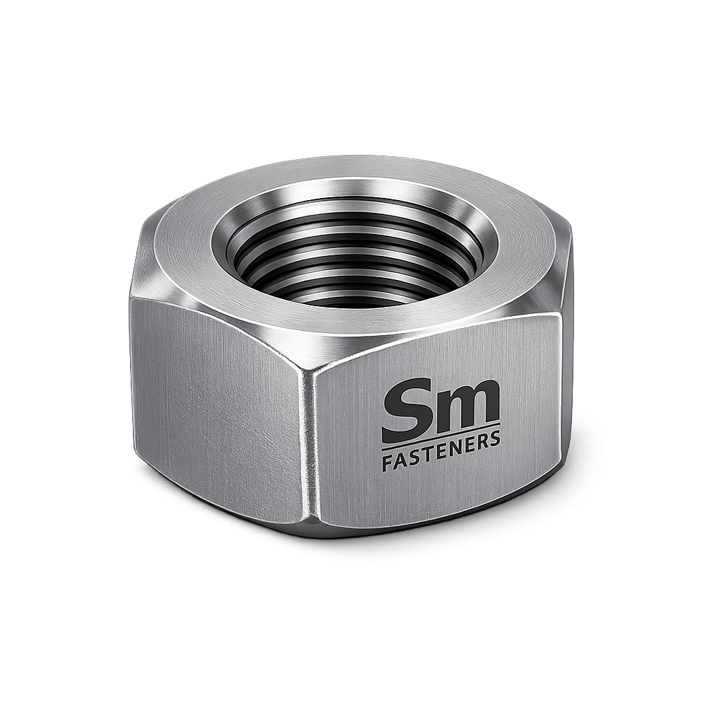
1.1 Role in Industrial Assemblies
The hex nut is the most widely deployed threaded fastener component in industrial bolted joint construction. In conjunction with a bolt, stud, or threaded rod, it provides the clamping force that maintains joint integrity under static, dynamic, thermal, and pressure loads. Its hexagonal external geometry enables application of controlled torque using standard open-end, box, and impact tooling across all industrial environments, including confined spaces and offshore platforms.
In critical service applications — flanged pipeline connections, pressure vessel closures, structural steel connections, and rotating machinery foundations — the hex nut is not a commodity component. Its property class, dimensional conformance, and material traceability are subject to the same engineering scrutiny as the primary pressure-containing component it secures.
1.2 Preference Over Alternatives
The hex nut is preferred over square nuts, cap nuts, and weld nuts in the following conditions:
- High-torque assembly: The six bearing faces distribute wrench load over a larger arc than four-face square nuts, reducing the risk of rounding under power tooling.
- Bidirectional access requirements: Hex geometry permits engagement from any of three tooling orientations.
- Standardised tooling inventory: One spanner size serves a defined range of metric or unified thread diameters per ISO 4762 and ANSI B18.2 series.
- Flange and bolted joint assembly: Full and heavy hex nuts meet ASME B16.5 and B16.47 dimensional requirements for pipe flange applications.
- Sour and corrosive service: Material variants (316L, Duplex 2205, Hastelloy C276) are available in hex nut geometry in full conformance with NACE MR0175/ISO 15156 hardness requirements.
1.3 Critical Design Parameters Governing Selection
The following parameters must be resolved at the design stage before specifying a hex nut:
- Thread designation (metric coarse/fine, UNC, UNF, BSW, BSF), nominal diameter, and pitch
- Property class or grade (ISO 898-2, ASTM A194, SAE J995)
- Material and corrosion resistance requirements per service environment
- NACE MR0175 compliance if H₂S partial pressure exceeds 0.0003 MPa absolute
- Width-across-flats (A/F) and bearing face geometry — standard vs heavy hex vs flange nut
- Nut factor (K) for torque-tension calculations per lubrication condition
- Surface finish and coating compatibility with mating bolt material (galvanic series)
1.4 Technical Definition
A hex nut (ISO 4032/DIN 934) is an internally threaded fastener with a regular hexagonal external profile, used to develop clamping force by rotation on a mating externally threaded fastener. The nut bears against a joint surface through its lower face (the bearing face), transmitting the axial clamping load developed by the torque applied to the hexagonal flats. Thread engagement depth equals nominal nut height, which is typically 0.8× the nominal diameter (style 1) or 1.0× (style 2 / heavy hex) to achieve the required proof load.
1.5 Clamping Force and Joint Preload Mechanics
When a torque T is applied to a nut on a bolt, the torque is distributed across three friction components:
- ~40%: Thread friction (between bolt and nut thread flanks)
- ~50%: Bearing face friction (nut face against joint surface)
- ~10%: Bolt stretching (generates axial preload / clamp load F)
This distribution illustrates why only a small fraction of applied torque converts to useful clamping force, and why lubrication condition and surface finish critically affect the torque-tension relationship.
Torque–Tension Relationship:
T = K × d × F
Where:
T = Applied tightening torque (N·m)
K = Nut factor (dimensionless) — typically 0.10–0.16 (lubricated), 0.18–0.22 (dry)
d = Nominal bolt diameter (m)
F = Resulting clamping force / preload (N)
Thread Engagement Requirement
Full thread engagement depth must equal at least 1× nominal diameter to develop proof load capacity per ISO 898-2. For soft or low-strength flange materials, engagement in tapped holes must be increased accordingly.
1.6 Failure Modes
Fatigue
Occurs under cyclic loading where the applied stress range exceeds the fatigue limit. In hex nuts, fatigue typically initiates at the first engaged thread root, where stress concentration is highest. Fatigue resistance improves with rolled threads, fine pitch, and surface compressive stress induced by thread rolling.
Shear Strip-Out
Thread stripping is the dominant failure mode when nut height is insufficient, when mating materials have a large hardness differential, or when overtightening exceeds the thread shear strength. Property class selection must ensure that the nut has higher proof load than the mating bolt to force failure into the bolt body rather than stripping the nut threads.
Hydrogen Embrittlement (HE)
Critical risk for heat-treated, high-strength fasteners (property class 10.9 and above) subjected to acid pickling or electroplating without a bake-out process. Hydrogen absorbed during surface treatment diffuses to grain boundaries under tensile stress, causing delayed brittle fracture. All electroplated high-strength hex nuts must undergo hydrogen embrittlement relief bake-out at 190–220°C for a minimum of 4–8 hours per ASTM F1624 and ISO 4042 requirements.
Stress Corrosion Cracking (SCC)
Occurs under the simultaneous presence of sustained tensile stress, a susceptible material, and a corrosive environment. Carbon steel and low-alloy steel nuts are susceptible in chloride environments. Austenitic stainless steels (304, 316) are susceptible in chloride-rich environments at elevated temperatures. Duplex and super duplex grades offer substantially improved SCC resistance in chloride service. Nickel alloys (Hastelloy, Inconel, Monel) provide the highest resistance in aggressive chemical environments.
2 . Types & Variants, Dimensional Design Logic, Standards & Compliance
2.1 Hex Nut Variants — Classification and Functional Differences
Hex Nut — Style 1 (ISO 4032 / DIN 934)
Standard nut height ≈ 0.8×d. Used for general industrial and structural applications where bolt and nut are matched by property class. The most widely specified nut in industrial procurement.
Hex Nut — Style 2 (ISO 4033 / DIN 6915)
Increased height ≈ 1.0×d for higher proof load. Preferred when nut stripping is a design risk or when fine-pitch threads are used. Standard for high-strength bolt assemblies in structural steelwork.
HEAVY HEX NUT (ASME B18.2.2 / ASTM A194)
Larger A/F width and greater height than standard hex nut of the same thread diameter. Provides a larger bearing area and is the mandatory specification for ASME B16.5 flange bolting in pipe systems. Available in 2H, 2HM, 7, 7M, and 8M grades.
Hex Flange Nut (ISO 4161 / DIN 6923)
Integral serrated or plain washer flange. Distributes bearing load over a larger area, eliminating the need for a separate washer. Used in automotive, machinery, and structural applications where vibration resistance is required.
Hex Thin Nut (ISO 4035 / DIN 439)
Reduced height ≈ 0.5×d. Used as a jam nut (locknut) in conjunction with a standard nut in locking assemblies. Not independently rated for full proof load.
Hex Coupling Nut (DIN 6334)
Extended length (approximately 3×d) for joining two threaded rods or extending bolt length. Used in structural tensioning systems, threaded rod assemblies, and turnbuckle applications.
Prevailing Torque Hex Nut — All-Metal Type (ISO 7042)
Deformed thread section or distorted crown provides frictional resistance against self-loosening. Rated for use at elevated temperatures. Used in vibrating machinery and hot process environments.
Prevailing Torque Hex Nut — Nylon Insert Type (ISO 7042 / DIN 985)
Nylon insert at the top of the nut deforms elastically onto bolt threads to resist loosening. Not suitable above 120°C. Used extensively in mechanical assemblies below temperature threshold.
High-Strength Structural Hex Nut (ASTM A563 / EN 14399-4)
Designated for structural bolted connections under AISC and Eurocode 3 requirements. Graded to match specific bolt grades in high-strength friction-grip (HSFG) assemblies.
Weld Hex Nut (DIN 929)
Three pilot projections on the bearing face allow resistance welding of the nut to sheet metal without fastener access from below. Used in automotive and fabrication applications.
2.2 Dimensional Design Logic
The A/F (width across flats) dimension of a hex nut is governed by the strength requirement of the torque application tool and the need to distribute bearing load across the joint face. The relationship between nominal thread diameter (d), A/F width, and nut height (m) follows a standardised progression to ensure that:
- Thread stripping strength in the nut equals or exceeds the proof load of the mating bolt body at the relevant property class combination.
- The bearing face area provides sufficient bearing stress capacity below the yield strength of the joint material.
- The nut can be installed with standard tooling from the same spanner set as the associated bolt head.
Fine-pitch variants (ISO 4032/4033 with fine pitch designation) are specified where vibration resistance, fine adjustment, or thinner wall thickness in the tapped component requires a smaller helix angle and increased thread engagement contact area per unit length.
Table 1 — Dimensional Reference (Metric Hex Nuts, ISO 4032)
| Nominal Size (d) | Thread Pitch (mm) | Width A/F (mm) | Width A/C (mm) | Nut Height m (mm) | Bearing Dia. (min mm) | Tolerance Class |
|---|---|---|---|---|---|---|
| M4 | 0.70 | 7.0 | 7.66 | 3.2 | 4.6 | 6H |
| M5 | 0.80 | 8.0 | 8.79 | 4.0 | 5.5 | 6H |
| M6 | 1.00 | 10.0 | 11.05 | 5.0 | 6.4 | 6H |
| M8 | 1.25 | 13.0 | 14.38 | 6.5 | 8.4 | 6H |
| M10 | 1.50 | 17.0 | 18.90 | 8.0 | 10.4 | 6H |
| M12 | 1.75 | 19.0 | 21.10 | 10.0 | 12.4 | 6H |
| M16 | 2.00 | 24.0 | 26.75 | 13.0 | 16.4 | 6H |
| M20 | 2.50 | 30.0 | 33.53 | 16.0 | 20.4 | 6H |
| M24 | 3.00 | 36.0 | 39.98 | 19.0 | 24.5 | 6H |
| M30 | 3.50 | 46.0 | 50.85 | 24.0 | 30.5 | 6H |
| M36 | 4.00 | 55.0 | 60.79 | 29.0 | 36.5 | 6H |
| M42 | 4.50 | 65.0 | 72.61 | 34.0 | 42.5 | 6H |
| M48 | 5.00 | 75.0 | 83.91 | 38.0 | 48.5 | 6H |
| M56 | 5.50 | 85.0 | 95.07 | 45.0 | 56.5 | 6H |
| M64 | 6.00 | 95.0 | 104.86 | 51.0 | 64.5 | 6H |
NOTE: A/C = width across corners. Heavy hex (ASME B18.2.2) A/F values are 2–4mm larger than standard. Fine-pitch variants available per ISO 8675 (style 1) and ISO 4035 (thin nut). For SM Fasteners weight data by size, refer to the SM Fasteners weight chart reference page.
2.3 Applicable Standards — Comprehensive Reference
ISO Standards
- ISO 4032 — Hex nuts, style 1 — product grades A and B
- ISO 4033 — Hex nuts, style 2 — product grades A and B
- ISO 4034 — Hex nuts, style 1 — product grade C
- ISO 4035 — Hex thin nuts (chamfered) — product grades A and B
- ISO 4036 — Hex thin nuts (unchamfered) — product grade B
- ISO 4161 — Hex flange nuts
- ISO 7042 — All-metal prevailing torque type hex nuts
- ISO 7719 — All-metal prevailing torque type hex nuts — fine pitch
- ISO 898-2 — Mechanical properties of fasteners: nuts with specified property classes
- ISO 8674 — Hex nuts, style 2, fine pitch — product grades A and B
- ISO 8675 — Hex thin nuts, fine pitch — product grades A and B
ASTM Standards
- ASTM A194/A194M — Carbon and alloy steel nuts for bolts for high-pressure or high-temperature service, or both (primary standard for process piping and pressure vessel bolting)
- ASTM A563 — Carbon and alloy steel nuts (structural bolting)
- ASTM F594 — Stainless steel nuts (UNC and UNF)
- ASTM F836M — Metric stainless steel hex nuts
- ASTM A453/A453M — High-temperature bolting with expansion coefficients comparable to austenitic steels (grades 651, 660, 662, 665)
DIN Standards
- DIN 934 — Hex nuts — ISO metric thread (superseded by ISO 4032 but still widely specified in European projects)
- DIN 935 — Hex castellated nuts
- DIN 985 — Prevailing torque hex nuts with nylon insert
- DIN 6923 — Hex flange nuts with serration
- DIN 6334 — Long hex coupling nuts
- DIN 439 — Hex thin nuts
British Standards
- BS 3692 — ISO metric precision hex bolts, screws and nuts
- BS 4190 — ISO metric black bolts, screws and nuts (product grade C)
- BS EN 24032 — Equivalent to ISO 4032 under CEN adoption
- BS 1769 — Metric series hex nuts for pipes and fittings
Property Class System — ISO 898-2 and ASTM A194
| Standard | Grade / Class | Material Basis | Proof Load (MPa) | Compatible Bolt Grade | Typical Application |
|---|---|---|---|---|---|
| ISO 898-2 | 5 | Carbon steel | 500 | Bolts 8.8 (to M16) | General structural |
| ISO 898-2 | 8 | Carbon/alloy steel | 800 | Bolts 8.8 | General structural |
| ISO 898-2 | 10 | Alloy steel, Q&T | 1040 | Bolts 10.9 | Heavy machinery, flanges |
| ISO 898-2 | 12 | Alloy steel, Q&T | 1150 | Bolts 12.9 | Critical fastening |
| ASTM A194 | 2H | Carbon steel, Q&T | 175 ksi (1207 MPa) | ASTM A193 B7 | Flanges, pressure vessels |
| ASTM A194 | 2HM | Carbon steel, NACE | 175 ksi | ASTM A193 B7M | Sour service (H₂S) |
| ASTM A194 | 8 | SS 304 | — | ASTM A193 B8 | Cryogenic, corrosive |
| ASTM A194 | 8M | SS 316 | — | ASTM A193 B8M | Marine, chemical process |
| ASTM A194 | 7 | Cr-Mo alloy | — | ASTM A193 B7 (elevated T) | High-temp service |
Part 3 of 4
Materials, Heat Treatment, Manufacturing Process & Surface Finishing
Table 3 — Material Comparison (Hex Nuts)
| Material | UTS (MPa) | 0.2% Yield (MPa) | Temp. Limit (°C) | Corrosion Resistance | Cost Index | Primary Application |
|---|---|---|---|---|---|---|
| Carbon Steel (Grade 8 / 2H) | 1000–1040 | 900 | +400 | Low — requires coating | 1.0 | General structural, flanges |
| Alloy Steel 42CrMo4 (Gr 10, 12) | 1040–1300 | 900–1100 | +450 | Low — requires coating | 1.4 | High-strength machinery |
| SS 304 / 304L (A2) | 500–700 | 200–450 | +870 | Good — moderate Cl⁻ media | 3.5 | Food, pharma, light chemical |
| SS 316 / 316L (A4) | 500–700 | 200–450 | +870 | Good — improved Mo content | 4.2 | Marine, chemical, offshore |
| Duplex 2205 (UNS S31803) | 620–820 | 450–620 | +300 | Very good — pitting & SCC | 5.5 | Subsea, seawater, desalination |
| Super Duplex 2507 (UNS S32750) | 730–930 | 530–730 | +300 | Excellent — PREN >42 | 7.0 | Offshore topsides, FPSOs |
| Hastelloy C276 (UNS N10276) | 690–793 | 310–380 | +1040 | Excellent — aggressive acids | 18.0 | Chemical process, FGD systems |
| Inconel 625 (UNS N06625) | 827–965 | 414–690 | +980 | Excellent — seawater, HCl | 20.0 | Subsea, aerospace, LNG |
| Incoloy 825 (UNS N08825) | 586–793 | 241–448 | +540 | Excellent — H₂SO₄, H₃PO₄ | 14.0 | Acid gas scrubbers, nuclear |
| Monel 400 (UNS N04400) | 480–690 | 170–345 | +480 | Excellent — HF, seawater | 15.0 | HF alkylation, marine |
| Nickel 200 (UNS N02200) | 380–550 | 100–345 | +315 | Good — caustic, fluorine | 13.0 | Caustic soda, electronics |
| SMO 254 (UNS S31254) | 650–750 | 300–400 | +400 | Excellent — high-Cl seawater | 9.0 | Desalination, bleach plants |
Cost index: carbon steel = 1.0 baseline. Values indicative; subject to market conditions and order volume.
Table 4 — Corrosion Resistance Matrix
| Material | Seawater | H₂SO₄ (dilute) | HCl (dilute) | H₂S / Sour Gas | Caustic (NaOH) | Crude Oil / Naphtha |
|---|---|---|---|---|---|---|
| Carbon Steel | Poor | Poor | Poor | Poor (SCC risk) | Fair (low conc.) | Good |
| SS 304 / 304L | Fair | Fair | Poor | Poor (SCC risk) | Good | Good |
| SS 316 / 316L | Good | Good | Fair | Poor (SCC risk) | Good | Good |
| Duplex 2205 | Very Good | Good | Good | Good (NACE HRC≤28) | Good | Very Good |
| Super Duplex 2507 | Excellent | Very Good | Very Good | Very Good | Good | Excellent |
| Hastelloy C276 | Excellent | Excellent | Excellent | Excellent | Very Good | Excellent |
| Inconel 625 | Excellent | Very Good | Very Good | Very Good | Very Good | Excellent |
| Incoloy 825 | Very Good | Excellent | Good | Very Good | Good | Very Good |
| Monel 400 | Excellent | Good | Good | Good | Excellent | Very Good |
| Nickel 200 | Good | Poor (oxidising) | Fair | Good | Excellent | Good |
| SMO 254 | Excellent | Very Good | Very Good | Very Good | Good | Excellent |
Rating scale: Excellent / Very Good / Good / Fair / Poor. Ratings reflect general service at ambient temperature; consult material supplier for elevated temperature or concentration-specific data.
3.Carbon and Alloy Steel Hex Nuts
3.1 Heat Treatment
- Normalising (860–900°C, air cool): Homogenises microstructure after hot forging. Used for medium-strength grades (property class 5, 6).
- Quench and Temper (Q&T): Austenitising at 830–870°C, water/oil quench, tempering at 550–650°C. Required for property class 10 and 12 nuts and ASTM A194 grade 2H. Produces martensitic microstructure with high strength and toughness.
- Stress Relieving (450–600°C): Applied after cold forming and thread rolling to reduce residual stresses without significantly altering mechanical properties.
Austenitic Stainless Steel (304, 316, 316L)
- Solution Annealing (1040–1100°C, rapid water quench): Dissolves chromium carbide precipitates formed during hot working, restoring corrosion resistance. Mandatory after hot forging. Produces fully austenitic, non-magnetic microstructure.
Duplex and Super Duplex Stainless Steels
- Solution Annealing (1020–1100°C for 2205; 1040–1120°C for 2507, water quench): Restores the prescribed austenite/ferrite phase balance (45–55% ferrite). Critical — improper heat treatment produces sigma phase embrittlement or excess ferrite reducing corrosion resistance.
Nickel Alloys (Inconel, Hastelloy, Incoloy, Monel)
- Solution Annealing / Mill Annealing: Dissolves secondary phases, restores ductility, and maximises corrosion resistance. Temperature and quench rate are alloy-specific.
- Age Hardening (Inconel 718): Precipitation hardening at 720°C/8h + 620°C/8h double-age cycle to develop γ″ phase strengthening.
NACE MR0175 / ISO 15156 Hardness Limits
For sour service (H₂S environments): Carbon and low-alloy steel nuts must not exceed 22 HRC (237 HBW). Austenitic SS and nickel alloys must be in the solution-annealed condition. Duplex grades must comply with specific hardness and microstructural requirements. Hardness testing on production lots is mandatory for NACE-compliant supply.
3.2 Manufacturing Process — Step by Step
- Raw material procurement: Bar, rod, or wire stock procured to material specification (ASTM, EN, ASME). Material Test Certificates (MTC) per EN 10204 3.1 (or 3.2 for nuclear/critical service) verified for heat number, chemical composition, and mechanical properties.
- Material traceability marking: Each heat/lot tagged and tracked through all production stages. Heat number cross-referenced to MTC maintained in production traveller.
- Blanking / Cold forging: Wire or bar sheared to precise blank weight. Cold heading on multi-station presses forms the hexagonal profile, bearing face chamfer, and through-hole. Cold forging is standard for nuts up to M24; hot forging used above M36 or for exotic alloys with low ductility.
- Hot forging (where applicable): Billet heated to 1100–1250°C (carbon steel) or alloy-specific temperature. Die-forged to achieve near-net hex shape. Flash trimmed. Suitable for large diameters and high-strength alloys.
- Heat treatment: Per material and grade requirement (see Section 3.1). Batch records maintained with furnace chart documentation.
- Thread tapping: Internal thread formed by tapping with spiral-point or spiral-flute taps to the specified thread form, pitch, and tolerance class (6H standard for metric). Thread rolling (form tapping) preferred over cut tapping where tool geometry permits — produces work-hardened thread flanks with improved fatigue and wear resistance and no chip generation.
- Chamfering and deburring: Bearing face chamfer formed to 15–30° per standard. Thread entry chamfered for ease of assembly. Deburring of all sharp edges.
- Surface treatment: Applied per specification (see Section 3.3 and Table 9).
- Dimensional inspection: 100% go/no-go thread gauging. Sample dimensional check of A/F, height, bearing face flatness, chamfer angle, and thread pitch/form per AQL plan.
- Mechanical testing: Proof load test on representative sample. Hardness verification. Tensile test on witness bar from same heat where required by specification.
- Marking: Property class / grade marking on hex face per ISO 898-2 or ASTM A194. Material identification marking per project or standard requirement. Manufacturer identification.
- Packing and documentation: VCI poly bag, bore and thread protection caps, export-grade carton. MTC, dimensional report, test certificates, CoC, CoO bundled per order documentation requirement.
3.3 Thread Cutting vs Thread Rolling — Technical Comparison
| Parameter | Thread Cutting (Tapping) | Thread Rolling (Form Tapping) |
|---|---|---|
| Material removal | Yes — chips generated | No — material displaced |
| Surface condition at thread root | Cut — residual tensile stress | Rolled — compressive residual stress |
| Fatigue resistance | Baseline | 20–30% improved |
| Surface finish (Ra) | 1.6–3.2 µm typical | 0.4–0.8 µm typical |
| Dimensional tolerance | 6H achievable | 6H achievable (preferred) |
| Applicable materials | All machinable alloys | Ductile materials only (>12% elongation) |
| Tool life | Moderate | Higher — no cutting edge wear |
Table 9 — Surface Finish Comparison
| Finish Type | Process Standard | Salt Spray (h) | Thickness (µm) | Temp. Limit (°C) | Thread Impact | Best Suited For |
|---|---|---|---|---|---|---|
| As-machined / Black | — | <24 | 0 | 500+ | None | Short-term, pre-coating |
| Black Oxide | MIL-DTL-13924 Cl.1 | 24–72 | 1–2 | 120 | Negligible | Temporary, appearance |
| Phosphating | ISO 9717 | 48–200 | 5–20 | 150 | Minimal | Primer for painting, lubricant retention |
| Zinc Electroplate — Clear | ISO 4042 / ASTM B633 | 72–120 | 5–8 | 120 | Must verify 6H after plating | General industrial, OEM |
| Zinc Electroplate — Yellow Chromate | ISO 4042 | 120–200 | 5–8 | 120 | Must verify 6H after plating | Marine, light outdoor |
| Hot-Dip Galvanising (HDG) | ISO 1461 / ASTM A153 | 1000–2000+ | 45–85 | 200 | Significant — oversized tap required | Structural steel, outdoor infrastructure |
| Dacromet / Geomet | ISO 10683 | 720–1000 | 5–12 | 300 | Minimal | Automotive, subsea, heavy corrosion |
| PTFE / Xylan Coating | Whitford Xylan spec | 500–1000 | 15–40 | 230 | Minimal | Low-friction, chemical, marine |
| Electroless Nickel (EN) | ASTM B733 | 500–1000 | 10–50 | 350 | Minimal (<12µm) | Oil & gas, electronics, wear resistance |
| Cadmium Plating | AMS QQ-P-416 | 500–1000 | 5–25 | 230 | Minimal | Aerospace, defence (restricted — RoHS) |
NOTE: High-strength nuts (property class 10, 12; ASTM A194 grade 2H) subjected to electroplating require hydrogen embrittlement relief bake-out at 190–220°C per ASTM F1624. Zinc electroplated nuts should be tested per ASTM F606 after plating to verify no strength loss. HDG nuts require oversized tapping or re-tapping of internal threads post-galvanising to restore 6H tolerance.
4.Inspection & QC, Applications, Export Capability & Technical Tables
4.1 Inspection & Quality Control
Dimensional Inspection
- Thread gauging: 100% inspection with calibrated GO/NO-GO gauges to the specified tolerance class (6H for metric; 2B for unified). Gauges calibrated per BS EN ISO 1502.
- A/F width: Measured with calibrated vernier or digital micrometer. Must conform to ISO 4032 limits (product grade A: tolerance class f7; grade B: e8).
- Height (m): Measured with digital height gauge on surface plate. Must fall within the min/max limits per standard and nominal size.
- Bearing face flatness and perpendicularity: Checked per ISO 4032 tolerance specification using dial gauge or CMM for critical applications.
- Chamfer angle and width: Visual and gauge verification, 15–30° to thread axis.
Mechanical Testing
- Proof load test: Mandatory per ISO 898-2 and ASTM A194. The nut is loaded axially to the specified proof load using a calibrated mandrel. No thread stripping, fracture, or permanent deformation permitted after removal of load.
- Hardness: Vickers (HV10 preferred), Brinell (HBW), or Rockwell (HRC) per applicable standard. For NACE-compliant supply: hardness must not exceed 22 HRC (237 HBW) on each individual tested piece — not an average.
- Tensile test: Performed on witness sample bars from the same heat treatment batch where specified by purchase order or standard (e.g., ASTM A194 large-diameter heavy hex nuts).
Non-Destructive Testing
- Magnetic Particle Inspection (MPI): Applied to carbon and alloy steel hex nuts in critical service to detect surface and near-surface discontinuities per ASTM E709 or ISO 9934.
- Liquid Penetrant Inspection (LPI): Applied to non-magnetic materials (austenitic SS, nickel alloys) to detect surface-breaking indications per ASTM E165 or ISO 3452.
- Ultrasonic Testing (UT): Applied to large-diameter (M56 and above) heavy hex nuts in nuclear, pressure vessel, or critical structural service.
Hydrogen Embrittlement Testing
All electroplated hex nuts with property class 10.9, 12.9, or ASTM A194 grade 2H must be tested per ASTM F1624 (incremental step loading) or ISO 15330 sustained load test. Testing performed after plating and bake-out. No failure within the specified load-hold duration constitutes acceptance.
PMI — Positive Material Identification
Mandatory for alloy grades (316L, Duplex, Super Duplex, Hastelloy, Inconel, Incoloy, Monel, SMO 254) on EPC and oil & gas projects. XRF (X-ray fluorescence) analysis conducted on a minimum 10% of pieces per lot, or as required by project specification. Chemical composition must conform to the UNS designation and applicable ASTM or EN standard. Results documented in PMI report and retained with MTC package.
SM Fasteners Quality System
SM Fasteners operates under an ISO 9001-certified quality management system, providing documented control over raw material traceability, process qualification, inspection records, and non-conformance management. Supply documentation for EPC and critical industrial projects is prepared in accordance with EN 10204 3.1 as standard, with 3.2 (witness/review by approved inspection body) available on request. MSME and UKAF registrations support supply to domestic and international project requirements.
Table 2 — Proof Load and Tensile Load by Grade and Size
| Size | Stress Area (mm²) | Cl.8 Proof Load (kN) | Cl.10 Proof Load (kN) | Cl.12 Proof Load (kN) | A194-2H Proof Load (kN) | Note |
|---|---|---|---|---|---|---|
| M8 | 36.6 | 26.4 | 38.1 | 42.1 | — | ISO 898-2 |
| M10 | 58.0 | 41.8 | 60.3 | 66.7 | — | ISO 898-2 |
| M12 | 84.3 | 60.7 | 87.7 | 96.9 | — | ISO 898-2 |
| M16 | 157 | 113 | 163 | 181 | — | ISO 898-2 |
| M20 | 245 | 176 | 255 | 282 | — | ISO 898-2 |
| M24 | 353 | 254 | 367 | 406 | — | ISO 898-2 |
| M30 | 561 | 404 | 583 | 645 | — | ISO 898-2 |
| M36 | 817 | 588 | 850 | 940 | — | ISO 898-2 |
| 1/2″-13 UNC | 126.7 | — | — | — | 133 kN | ASTM A194 2H |
| 3/4″-10 UNC | 284.9 | — | — | — | 299 kN | ASTM A194 2H |
| 1″-8 UNC | 506.7 | — | — | — | 532 kN | ASTM A194 2H |
| 1-1/4″-7 UNC | 793.5 | — | — | — | 834 kN | ASTM A194 2H |
| 1-1/2″-6 UNC | 1140.1 | — | — | — | 1198 kN | ASTM A194 2H |
Proof load = Proof load stress (MPa) × Stress area. ISO class 8 proof stress = 720 MPa; class 10 = 1040 MPa; class 12 = 1150 MPa. ASTM A194 grade 2H proof stress = 175 ksi (1207 MPa).
Table 5 — Mechanical Properties by Grade and Standard
| Grade / Standard | Yield Str. (MPa) | UTS (MPa) | Elong. (%) | Hardness (HV/HBW) | Impact (J at °C) |
|---|---|---|---|---|---|
| ISO 898-2, Class 5 | Min 500 | — | — | 130–302 HV | — |
| ISO 898-2, Class 8 | Min 800 | — | — | 160–302 HV | — |
| ISO 898-2, Class 10 | Min 1040 | — | — | 272–353 HV | — |
| ISO 898-2, Class 12 | Min 1150 | — | — | 295–353 HV | — |
| ASTM A194 Gr 2H | Min 896 (130 ksi) | Min 1034 | Min 14 | Max 352 HBW | — |
| ASTM A194 Gr 8 (304) | Min 207 | Min 483 | Min 30 | Max 192 HBW | — |
| ASTM A194 Gr 8M (316) | Min 207 | Min 483 | Min 30 | Max 192 HBW | — |
| Duplex 2205 (A182 F51) | Min 450 | Min 620 | Min 25 | Max 293 HBW | 27J @ −20°C |
| Super Duplex 2507 (A182 F55) | Min 530 | Min 730 | Min 25 | Max 310 HBW | 27J @ −20°C |
| Hastelloy C276 (SB-574) | Min 310 | Min 690 | Min 40 | 100–250 HBW | Excellent |
| Inconel 625 (SB-446) | Min 414 | Min 827 | Min 30 | ≤250 HBW | Excellent |
| Monel 400 (SB-164) | Min 170 | Min 480 | Min 35 | ≤241 HBW | Good |
Table 6 — Recommended Tightening Torque (Nm)
| Size | Class 8.8 Dry | Class 8.8 Lubricated (K=0.15) | Class 10.9 Dry | Class 10.9 Lubricated | A193 B7 / A194 2H Dry | A193 B7 / A194 2H Lubricated |
|---|---|---|---|---|---|---|
| M8 | 25 | 18 | 35 | 26 | — | — |
| M10 | 50 | 36 | 70 | 51 | — | — |
| M12 | 87 | 63 | 121 | 88 | — | — |
| M16 | 210 | 152 | 294 | 214 | — | — |
| M20 | 420 | 305 | 588 | 427 | — | — |
| M24 | 730 | 530 | 1020 | 740 | — | — |
| M30 | 1450 | 1052 | 2034 | 1476 | — | — |
| 1/2″-13 | — | — | — | — | 95 | 69 |
| 3/4″-10 | — | — | — | — | 339 | 246 |
| 1″-8 | — | — | — | — | 814 | 591 |
| 1-1/4″-7 | — | — | — | — | 1627 | 1181 |
| 1-1/2″-6 | — | — | — | — | 2847 | 2067 |
Dry K ≈ 0.20; Lubricated K ≈ 0.145 (MoS₂ or anti-seize). Torque values are for 75% proof load target preload. For galling-prone stainless/nickel alloy studs and nuts, anti-galling lubricant (Molykote, Loctite N-5000, Jet-Lube SS-30) is mandatory. Do not use torque values derived for steel on stainless steel assemblies without adjustment.
Table 7 — Preload Calculation Guide
Fundamental Preload Formula
Step 1: Determine target preload (F)
F = 0.75 × Fp
Where Fp = Proof load = Ap × Sp
Ap = Thread stress area (mm²), Sp = Proof load stress (MPa)
Step 2: Calculate required torque
T = K × d × F
Step 3: Verify bearing stress
σ_bear = F / A_bear ≤ 0.9 × Fy (joint material)
A_bear = π/4 × (D_washer² – D_hole²)
Step 4: Thread stripping check
τ_strip = F / (0.5π × d × L_eng × √3)
Where L_eng = thread engagement length
Worked Example — M24 Class 10.9 Bolt / Class 10 Nut, Lubricated
| Parameter | Value | Source / Calculation |
|---|---|---|
| Nominal diameter d | 24 mm = 0.024 m | Specified |
| Thread stress area Ap | 353 mm² | ISO 898-1 Table |
| Proof load stress Sp | 1040 MPa | ISO 898-2, Class 10 |
| Proof load Fp | 353 × 1040 = 367,120 N = 367.1 kN | Fp = Ap × Sp |
| Target preload F | 0.75 × 367.1 = 275.3 kN | F = 0.75 × Fp |
| Nut factor K (lubricated, MoS₂) | 0.145 | Industry reference |
| Required torque T | 0.145 × 0.024 × 275,300 = 957 N·m | T = K × d × F |
| Bearing stress σ_bear | 275,300 / ((π/4)(55² – 26²)) = 171 MPa | A/F=55mm, hole=26mm |
| Joint material Fy (S275) | 275 MPa | EN 10025 S275 |
| Bearing stress check | 171 MPa ≤ 0.9 × 275 = 247 MPa ✓ | Acceptable |
Table 8 — Thread Form and Tolerance Compatibility
| Thread System | Standard | Designation Example | Pitch Basis | Nut Tolerance Class | Interchangeability |
|---|---|---|---|---|---|
| ISO Metric Coarse | ISO 724 / ISO 965-1 | M24 × 3.0 — 6H | Metric (mm) | 6H (general use), 5H (precision) | Metric only |
| ISO Metric Fine | ISO 8675 | M24 × 2.0 — 6H | Metric (mm) | 6H | Metric fine only |
| UNC (Unified Coarse) | ASME B1.1 | 1″-8 UNC — 2B | TPI (threads/inch) | 2B (standard), 3B (precision) | Unified only |
| UNF (Unified Fine) | ASME B1.1 | 1″-12 UNF — 2B | TPI | 2B | Unified fine only |
| BSW (Whitworth Coarse) | BS 84 | 1″ BSW | TPI (55° flank angle) | Medium (BS 84) | BSW only — NOT interchangeable with UNC/Metric |
| BSF (Whitworth Fine) | BS 84 | 1″ BSF | TPI (55° flank angle) | Medium | BSF only |
| BSPP / G Thread | ISO 228 / BS EN 10226 | G1″ (cylindrical) | TPI (55° flank, parallel) | ISO 228 tolerance | Sealing by thread compound |
| BSPT / R Thread | ISO 7 / BS EN 10226 | R1″ (taper) | TPI (55° flank, taper) | ISO 7 tolerance | Sealing by thread interference |
Critical note: ISO Metric (60° flank) and BSW/BSF (55° flank) threads are NOT interchangeable despite similar nominal dimensions. Mixing thread systems causes assembly damage and constitutes a critical non-conformance in industrial service applications.
Table 10 — Weight Reference (Metric Hex Nuts, Carbon Steel, ISO 4032)
| Size | A/F (mm) | Height (mm) | Wt/pc (g) | Wt/100 pcs (kg) | Wt/1000 pcs (kg) | Notes |
|---|---|---|---|---|---|---|
| M6 | 10.0 | 5.0 | 2.0 | 0.20 | 2.0 | Standard hex |
| M8 | 13.0 | 6.5 | 4.5 | 0.45 | 4.5 | |
| M10 | 17.0 | 8.0 | 8.6 | 0.86 | 8.6 | |
| M12 | 19.0 | 10.0 | 14.2 | 1.42 | 14.2 | |
| M16 | 24.0 | 13.0 | 33.6 | 3.36 | 33.6 | |
| M20 | 30.0 | 16.0 | 65.0 | 6.50 | 65.0 | |
| M24 | 36.0 | 19.0 | 113.0 | 11.3 | 113.0 | |
| M30 | 46.0 | 24.0 | 230.0 | 23.0 | 230.0 | |
| M36 | 55.0 | 29.0 | 399.0 | 39.9 | 399.0 | |
| M42 | 65.0 | 34.0 | 649.0 | 64.9 | 649.0 | |
| M48 | 75.0 | 38.0 | 971.0 | 97.1 | 971.0 | |
| M56 | 85.0 | 45.0 | 1556.0 | 155.6 | 1556.0 | Large dia. |
| M64 | 95.0 | 51.0 | 2303.0 | 230.3 | 2303.0 |
Weights are theoretical for carbon steel (density 7.85 g/cm³), ISO 4032 style 1. Stainless steel: ×1.01–1.02 (negligible). Inconel/Hastelloy: ×1.09–1.11 (higher density). Monel: ×1.10. For complete weight-per-piece charts across all SM Fasteners product ranges, refer to the SM Fasteners weight chart reference page at smfastners.com.
4.2 Applications — Industry-Specific Mapping
Construction & Structural Steel
Hex nuts to ASTM A563 grades A, C, D, DH, and DH3 are used in high-strength friction-grip (HSFG) and bearing-type bolted connections per AISC 360 and Eurocode 3. Heavy hex nuts are standard for anchor bolts and column base plate connections. Hot-dip galvanised nuts (ISO 1461) are specified for exposed structural steelwork in corrosive environments.
Oil & Gas — Upstream, Midstream, Downstream
ASTM A194 grade 2H heavy hex nuts are the baseline specification for flanged connections in process piping per ASME B31.3 and B31.4. Sour service environments (H₂S partial pressure above threshold per ISO 15156) require grade 2HM (max 22 HRC) or stainless/nickel alloy alternatives. Subsea and offshore applications require high-alloy materials (Duplex 2205/2507, Inconel 625, SMO 254) with full material traceability and EN 10204 3.1 or 3.2 documentation.
Power Generation
Thermal power plant fastening requires alloy steel studs and nuts conforming to ASTM A193/A194 for steam temperatures up to 550°C. Nuclear service applications require material conformance to ASME BPVC Section III, with documentation and NDE per NQA-1. Wind turbine tower flanges use structural hex nuts to EN 14399-4/6 in conjunction with HV bolts.
Petrochemical & Chemical Processing
Process plant flanged connections operating in corrosive or high-temperature environments require material selection based on the process fluid corrosivity matrix. Hastelloy C276, Incoloy 825, and Monel 400 nuts are specified for aggressive acid, HF, and chloride service. Nickel 200 is used in caustic soda service.
LNG Terminals
Cryogenic service (operating temperatures down to −165°C) requires materials maintaining adequate toughness and ductility at low temperature. Austenitic stainless steels (316L), 9% Ni steel, and Inconel alloys are the preferred materials for LNG bolting. Charpy impact testing at cryogenic temperature (typically −196°C) is a mandatory qualification requirement.
Shipbuilding & Offshore Structures
Marine atmospheric and immersed zone applications require minimum SS 316 or high-alloy specification. Subsea bolt and nut assemblies are subject to cathodic protection interaction — hydrogen embrittlement risk for high-strength materials in cathodically protected systems must be evaluated, and high-strength steel grades avoided below −850 mV Ag/AgCl in favour of nickel alloys.
Semiconductor, Medical, Chemical & Electrical Insulation — PEEK Fasteners
Where metal contamination, electrical conductivity, or MRI compatibility is a disqualifying factor, SM Fasteners supplies hex nuts in PEEK (polyether ether ketone). PEEK provides continuous service temperature to 260°C, chemical resistance to most organic solvents and acids, UTS of approximately 100 MPa, and inherent electrical insulation (dielectric strength ~19 kV/mm). PEEK hex nuts are specified in semiconductor fab equipment, MRI imaging components, chemical dosing systems, and electrical insulation-critical assemblies where metallic fasteners are not permissible.
4.3 Export Documentation & Packaging Capability
Packaging Standards
- Thread and bore protection: polypropylene end caps and bore plugs on all nuts M16 and above.
- VCI (Volatile Corrosion Inhibitor) poly bag inner packaging for ferrous grades.
- Moisture-resistant outer carton with waterproof label; net weight, gross weight, dimensions clearly marked.
- Export wooden crating with ISPM-15 fumigation-free treatment certification where required for international airfreight or sea freight.
Documentation Package (Standard for EPC / Critical Industrial Supply)
- EN 10204 3.1 MTC: Issued by manufacturer’s quality department; chemical composition, mechanical properties, heat treatment records, heat/lot number.
- EN 10204 3.2 MTC: Available on request — requires co-review and endorsement by an accredited third-party inspection authority (TPI) or the purchaser’s own representative.
- Dimensional Inspection Report: CMM or manual measurement records covering A/F, height, thread tolerance, bearing face flatness.
- Heat Treatment Certificate: Furnace chart, temperature, hold time, quench medium, batch identification.
- Test Certificate: Proof load, hardness, tensile (where applicable), Charpy (where applicable).
- NDT Report: MPI/LPI/UT results where specified.
- PMI Report: XRF analysis results for alloy grades.
- Certificate of Conformance (CoC): Confirming supply conforms to specified standard, grade, and purchase order requirements.
- Certificate of Origin (CoO): For customs and trade compliance purposes.
- Packing List: Per shipment, with heat/lot traceability to package.
Custom Fastener Capability — SM Fasteners
SM Fasteners’ custom fastener capability covers non-standard A/F dimensions, special thread forms (ACME, trapezoidal, stub ACME, left-hand thread), modified bearing face geometries, compound multi-feature nuts, and material specifications beyond standard grades. EPC project enquiries requiring deviation from standard catalogue items are supported through a documented engineering review and qualification process under the ISO 9001 quality management system.