

Flange Nut
1. Industry Context
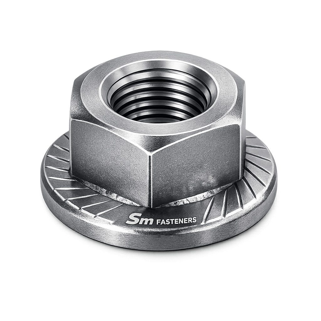
Flange nuts are critical fastening components developed to improve load distribution, vibration resistance, and joint reliability in mechanically loaded assemblies. Unlike conventional hex nuts requiring separate washers, flange nuts integrate a bearing flange directly into the nut geometry, simplifying assembly while improving performance consistency.
Across global industries, flange nuts are extensively deployed where:
- Assembly speed must be optimized
- Surface damage must be minimized
- Load distribution over thin or softer materials is required
- High vibration environments exist
- Repeatable torque–tension performance is essential
Major Industrial Deployment Sectors
| Industry | Functional Requirement |
|---|---|
| Structural Steel | Load spreading & reduced embedment |
| Oil & Gas | Reliable preload under vibration |
| Power Generation | Thermal cycling resistance |
| Automotive & OEM | High-speed automated assembly |
| Petrochemical | Corrosion-resistant clamping |
| Heavy Equipment | Shock & dynamic load resistance |
| Rail & Infrastructure | Long-life maintenance-free joints |
| Offshore & Marine | Corrosion + vibration control |
SM Fasteners manufactures flange nuts aligned with ISO 9001-certified quality systems, enabling traceable supply suitable for EPC projects and third-party inspection environments.
2. Technical Definition
A flange nut is a hexagonal internally threaded fastener incorporating an integral washer-like flange at the bearing surface.
Key Functional Elements
- Hex body for torque application
- Internal precision thread
- Integrated flange (plain or serrated)
- Enlarged bearing surface
The flange performs two essential engineering functions:
- Redistributes compressive load
- Increases frictional resistance
This eliminates the need for separate washers while improving joint stability.
3. Load Mechanics & Force Behavior
3.1 Fundamental Fastener Principle
All bolted joints operate by converting tightening torque into clamping force (preload).
Where:
- T = Applied torque
- K = Nut factor (friction coefficient)
- F = Preload force
- D = Nominal diameter
Flange nuts influence this relationship by modifying the bearing friction component.
3.2 Force Distribution Mechanism
Standard hex nuts concentrate compressive stress under a limited contact area.
Flange nuts increase contact area by 30–70%, producing:
- Lower bearing stress
- Reduced joint embedment
- Improved fatigue life
Stress Distribution Comparison
| Parameter | Hex Nut | Flange Nut |
|---|---|---|
| Contact Area | Small | Large |
| Surface Damage Risk | Higher | Reduced |
| Washer Requirement | Yes | No |
| Load Distribution | Concentrated | Distributed |
| Assembly Time | Longer | Faster |
3.3 Preload Behavior
Preload must exceed service loads to prevent joint separation.
Flange geometry stabilizes preload through:
- Reduced localized yielding
- Controlled friction interface
- Lower settlement losses
Typical preload target:
3.4 Torque–Tension Relationship
Torque energy distribution:
| Energy Component | Percentage |
|---|---|
| Thread Friction | 40–50% |
| Bearing Surface Friction | 35–45% |
| Useful Bolt Stretch | 10–15% |
The flange modifies bearing friction, improving repeatability during controlled tightening.
4. Joint Design Principles
4.1 Washer Elimination Strategy
Flange nuts replace washers where:
- Space constraints exist
- Automated assembly lines operate
- Assembly consistency is required
Engineering benefits include:
- Reduced component count
- Lower installation error probability
- Improved inventory control
4.2 Joint Stiffness Considerations
Joint stiffness ratio:
Where:
- Kb = Bolt stiffness
- Kj = Joint stiffness
Flange nuts increase effective joint stiffness by enlarging compression zones.
4.3 Vibration Resistance
Serrated flange nuts create mechanical locking through:
- Radial tooth engagement
- Micro-penetration into mating surface
- Increased prevailing torque
Common in:
- Automotive suspension
- Rotating equipment
- Railway assemblies
4.4 Bearing Pressure Control
Bearing stress:
Increasing flange area reduces stress concentration, preventing:
- Surface brinelling
- Coating damage
- Relaxation losses
4.5 Failure Prevention Philosophy
Correctly specified flange nuts mitigate:
- Self-loosening
- Fretting corrosion
- Fatigue cracking
- Embedment relaxation
5. Functional Role in Industrial Assemblies
flange nuts act as:
- Load distributors
- Anti-loosening devices
- Assembly simplifiers
- Structural preload stabilizers
SM Fasteners engineers flange nuts suitable for high integrity joints used in global EPC projects.
Typical Engineering Assemblies
| Assembly | Function |
|---|---|
| Structural connections | Load spreading |
| Pump skids | Vibration resistance |
| Pressure equipment | Uniform compression |
| Automotive chassis | Rapid installation |
| Offshore modules | Corrosion resistance |
6. Mechanical Behavior Under Service Loads
Static Loading
Maintains clamping force preventing separation.
Dynamic Loading
Flange increases friction damping.
Thermal Cycling
Large bearing area minimizes preload loss.
Shock Loading
Distributes impulse stresses.
7. Thread Engagement Requirements
Minimum engagement:
| Material | Engagement Length |
|---|---|
| Steel | 1 × Diameter |
| Stainless Steel | 1.25 × Diameter |
| Aluminum | 2 × Diameter |
8. Common Failure Mechanisms
Fatigue Failure
Caused by fluctuating tensile stress.
Mitigation: Proper preload + flange load distribution.
Shear Failure
Occurs when joint slips.
Mitigation: Correct preload selection.
Hydrogen Embrittlement
Risk in high-strength plated fasteners.
Control: Certified baking procedures at SM Fasteners.
Stress Corrosion Cracking
Critical in:
- Chloride environments
- H₂S service
Materials selected according to NACE MR0175 / ISO 15156.
9. Friction & Nut Factor Influence
Typical nut factor values:
| Condition | K Value |
|---|---|
| Dry | 0.20–0.25 |
| Zinc Plated | 0.18 |
| Lubricated | 0.12–0.15 |
| PTFE Coated | 0.10–0.13 |
Flange surface finish directly affects tightening accuracy.
10. Engineering Selection Criteria
Selection must consider:
- Bolt grade compatibility
- Operating temperature
- Corrosion environment
- Required preload
- Installation method
- Inspection accessibility
SM Fasteners supports custom engineering for project-specific flange nut configurations, including advanced alloys and PEEK polymer fasteners for electrically isolated or chemically aggressive environments.
11. Product Types and Variants
Flange nuts are engineered in multiple configurations to address specific mechanical, environmental, and installation requirements. Selection must consider vibration conditions, surface hardness, accessibility, and preload reliability.
11.1 Standard Hex Flange Nut (Plain Bearing Face)
Description
- Integral washer flange
- Smooth bearing surface
- Non-locking configuration
Engineering Purpose
- Load spreading
- Surface protection
- Assembly simplification
Typical Applications
- Structural steel connections
- General machinery
- Pressure equipment assemblies
- EPC skid fabrication
11.2 Serrated Flange Nut (Prevailing Torque Type)
Design Characteristics
- Radial serrations under flange
- Self-locking action
- Increased friction resistance
Functional Mechanism
Serrations create micro-penetration into mating material, increasing resistance against rotational loosening.
Advantages
- Eliminates lock washers
- Excellent vibration resistance
- Improved preload retention
Limitations
- Not recommended for coated or painted surfaces requiring preservation
- Not suitable for soft materials
11.3 Heavy Series Flange Nut
Features
- Increased height
- Larger thread engagement
- Higher load capacity
Used where:
- High tensile bolts (10.9 / 12.9)
- Structural applications
- Heavy equipment joints
11.4 Metric vs Unified Flange Nuts
| Thread System | Primary Regions | Standard Use |
|---|---|---|
| Metric (ISO) | Europe, India, Middle East | EPC & infrastructure |
| UNC | North America | Structural & heavy equipment |
| UNF | Aerospace & precision | High fatigue resistance |
| BSW | Legacy UK systems | Maintenance retrofit |
| BSF | Fine pitch British | Older installations |
SM Fasteners manufactures flange nuts compatible with global interchangeability requirements.
11.5 High-Temperature Alloy Flange Nuts
Manufactured in:
- Inconel
- Incoloy
- Hastelloy
- Nickel alloys
- SMO 254
Applications include:
- Gas turbines
- Refinery heaters
- LNG cryogenic systems
11.6 Corrosion-Resistant Stainless Flange Nuts
Common grades:
- A2-70 / 304
- A4-80 / 316
- Duplex 2205
- Super Duplex 2507
Designed for:
- Offshore exposure
- Chemical processing
- Marine environments
11.7 PEEK Flange Nuts (Advanced Polymer Variant)
SM Fasteners supplies precision PEEK flange nuts where metal fasteners are unsuitable.
Advantages
- Electrically insulating
- Chemical resistant
- Lightweight
- Non-magnetic
- Radiation resistant
Typical Uses
- Semiconductor equipment
- Chemical plants
- Medical systems
- Electrical assemblies
12. Dimensional Logic and Engineering Geometry
The geometry of flange nuts is designed according to standardized proportional relationships ensuring predictable load transfer and compatibility.
12.1 Critical Dimensions
| Symbol | Description |
|---|---|
| d | Thread diameter |
| P | Thread pitch |
| m | Nut height |
| s | Width across flats |
| dc | Flange diameter |
| k | Flange thickness |
| r | Fillet radius |
12.2 Dimensional Specification Table — Metric Flange Nuts
(Typical ISO/DIN reference dimensions)
| Size | Pitch (mm) | Height m (mm) | Across Flats s (mm) | Flange Dia dc (mm) | Weight/pc (g) |
|---|---|---|---|---|---|
| M5 | 0.8 | 5 | 8 | 11.8 | 1.1 |
| M6 | 1.0 | 6 | 10 | 14.2 | 2.3 |
| M8 | 1.25 | 8 | 13 | 17.9 | 5.0 |
| M10 | 1.5 | 10 | 15 | 21.8 | 9.5 |
| M12 | 1.75 | 12 | 18 | 26.0 | 16 |
| M16 | 2.0 | 16 | 24 | 34.5 | 36 |
| M20 | 2.5 | 20 | 30 | 43 | 75 |
| M24 | 3.0 | 24 | 36 | 51 | 145 |
(Weights aligned with SM Fasteners manufacturing data ranges)
12.3 Weight Chart — Procurement Reference
| Size | Weight / Piece (kg) | Weight / 100 pcs (kg) |
|---|---|---|
| M6 | 0.0023 | 0.23 |
| M8 | 0.005 | 0.50 |
| M10 | 0.0095 | 0.95 |
| M12 | 0.016 | 1.60 |
| M16 | 0.036 | 3.60 |
| M20 | 0.075 | 7.50 |
| M24 | 0.145 | 14.50 |
Used for:
- Freight estimation
- EPC BOQ calculations
- Export packing planning
13. Thread Geometry Engineering
13.1 Thread Form Standards
| Standard | Included Angle | Application |
|---|---|---|
| ISO Metric | 60° | Global industrial |
| UNC | 60° | Structural |
| UNF | 60° | Fatigue resistance |
| BSW | 55° | Legacy systems |
| BSF | 55° | Maintenance projects |
13.2 Thread Tolerance Classes
| System | External Thread | Internal Thread |
|---|---|---|
| ISO Metric | 6g | 6H |
| UNC/UNF | 2A | 2B |
| Precision Fit | 3A | 3B |
Proper tolerance prevents:
- Galling
- Misalignment
- Preload scatter
14. Applicable International Standards
Flange nuts must comply with internationally recognized dimensional and mechanical standards.
14.1 ISO Standards
| Standard | Scope |
|---|---|
| ISO 4161 | Hexagon flange nuts |
| ISO 4032 | Hex nuts reference |
| ISO 898-2 | Mechanical properties |
| ISO 965 | Thread tolerances |
| ISO 3506 | Stainless steel fasteners |
14.2 DIN Standards
| Standard | Description |
|---|---|
| DIN 6923 | Hex flange nuts |
| DIN 267 | Mechanical requirements |
| DIN EN 10204 | Inspection certification |
14.3 ASTM Standards
| Standard | Application |
|---|---|
| ASTM A563 | Carbon steel nuts |
| ASTM A194 | Pressure vessel nuts |
| ASTM F594 | Stainless steel nuts |
| ASTM B637 | Nickel alloy fasteners |
14.4 British Standards (BS)
| Standard | Description |
|---|---|
| BS 4190 | Hexagon nuts |
| BS 3692 | Metric precision |
| BS EN ISO equivalents | International harmonization |
15. Property Class System (Mechanical Strength Classification)
Metric flange nuts follow ISO property class designation.
| Property Class | Compatible Bolt | Typical Application |
|---|---|---|
| 5 | 5.8 bolts | Light structures |
| 8 | 8.8 bolts | General engineering |
| 10 | 10.9 bolts | Heavy machinery |
| 12 | 12.9 bolts | High-load systems |
Rule:
Nut property class ≥ bolt property class
16. Interchangeability & Global Procurement Logic
EPC procurement requires interchangeability across standards.
Critical Factors
- Thread compatibility
- Height equivalence
- Bearing diameter
- Proof load compliance
SM Fasteners supports:
- Metric ↔ UNC conversions
- Project-specific drawings
- Custom flange geometry manufacturing
17. Engineering Geometry Impact on Performance
Larger Flange Diameter Results In:
✔ Reduced bearing pressure
✔ Improved fatigue resistance
✔ Higher vibration tolerance
✔ Better coating life
Flange Thickness Influence
| Thickness | Effect |
|---|---|
| Thin | Lightweight assemblies |
| Medium | Standard industrial |
| Thick | Structural loading |
18. Serration Geometry Considerations
Serration angle and depth determine locking performance.
Parameters include:
- Tooth pitch
- Penetration depth
- Surface hardness compatibility
Used where repeated loosening risk exists.
19. Design Compatibility with Automated Assembly
Flange nuts are optimized for:
- Robotic tightening
- High-speed assembly lines
- Torque-controlled tools
- Angle-controlled tightening systems
Integrated flange improves positional stability during installation.
20. Engineering Selection Matrix — Type vs Application
| Application | Recommended Type |
|---|---|
| Structural steel | Plain flange |
| Automotive | Serrated flange |
| Offshore | Stainless flange |
| High temperature | Nickel alloy |
| Electrical isolation | PEEK flange nut |
| Chemical processing | Duplex/Super Duplex |
21. Material Grades and Selection Criteria
Material selection is the most critical engineering decision affecting flange nut performance. The selected material must simultaneously satisfy:
- Mechanical strength requirements
- Corrosion resistance
- Temperature capability
- Hydrogen service compatibility
- Fabrication and coating suitability
- Lifecycle cost expectations
SM Fasteners manufactures flange nuts using certified raw materials supported by EN 10204 3.1 traceable Mill Test Certificates under ISO 9001 quality management systems.
21.1 Carbon Steel Flange Nuts
Carbon steel remains the most widely used material for structural and industrial assemblies.
| Grade | Standard | Typical Property Class | Application |
|---|---|---|---|
| Low Carbon Steel | ISO / ASTM A563 A | Class 5 | Light duty |
| Medium Carbon Steel | ASTM A563 DH | Class 8 | Structural |
| Alloyed Carbon Steel | ASTM A563 DH3 | Class 10 | Heavy equipment |
| High Strength Alloy Steel | ISO 898-2 | Class 12 | High preload joints |
Advantages
- High strength-to-cost ratio
- Excellent machinability
- Suitable for coating systems
21.2 Stainless Steel Flange Nuts
Used where corrosion resistance dominates design requirements.
| Grade | ISO Class | Corrosion Resistance | Typical Industry |
|---|---|---|---|
| SS 304 (A2-70) | A2 | Atmospheric | Construction |
| SS 316 (A4-80) | A4 | Marine/chemical | Offshore |
| 316L | A4 | Chloride exposure | Petrochemical |
| 321 | Stabilized | High temperature | Exhaust systems |
21.3 Duplex & Super Duplex Stainless Steel
Engineered for aggressive offshore and sour environments.
| Material | Yield Strength | Corrosion Resistance | Service |
|---|---|---|---|
| Duplex 2205 | High | Excellent | Offshore structures |
| Super Duplex 2507 | Very High | Extreme | Seawater systems |
Benefits:
- High resistance to pitting corrosion
- Excellent SCC resistance
- Lower weight vs carbon steel for equal strength
21.4 Nickel Alloy Flange Nuts
SM Fasteners supplies high-performance alloys for extreme environments.
| Alloy | Temperature Limit | Key Resistance |
|---|---|---|
| Inconel 625 | ~1000°C | Oxidation |
| Inconel 718 | ~700°C | Creep strength |
| Hastelloy C276 | Severe acids | Chemical resistance |
| Monel 400 | Marine | Saltwater corrosion |
| Incoloy 825 | Acidic service | SCC resistance |
| SMO 254 | Chloride environments | Pitting resistance |
21.5 PEEK Flange Nuts — Advanced Polymer Engineering
PEEK fasteners supplied by SM Fasteners address applications where metals fail.
Mechanical Characteristics
- Continuous service temperature: 250°C
- High dielectric strength
- Chemical inertness
- Radiation resistance
Applications
- Semiconductor processing
- Medical equipment
- Aerospace electronics
- Chemical dosing systems
22. Material Selection Criteria Matrix
| Parameter | Carbon Steel | Stainless | Duplex | Nickel Alloy | PEEK |
|---|---|---|---|---|---|
| Strength | High | Medium | High | High | Low-Medium |
| Corrosion Resistance | Low | Good | Excellent | Extreme | Excellent |
| Temperature Range | 300°C | 600°C | 300°C | 1000°C | 250°C |
| Cost | Low | Medium | High | Very High | High |
| Weight | Medium | Medium | Medium | High | Very Low |
| Typical Use | Structural | Marine | Offshore | Chemical/LNG | Electrical |
23. Mechanical Properties by Property Class
| Property Class | Proof Stress (MPa) | Tensile Strength (MPa) | Hardness (HV) |
|---|---|---|---|
| Class 5 | 500 | 500–600 | 150–200 |
| Class 8 | 800 | 800–900 | 220–300 |
| Class 10 | 1000 | 1000–1100 | 300–360 |
| Class 12 | 1200 | 1200–1300 | 350–420 |
24. Heat Treatment Processes
Heat treatment determines final mechanical performance and reliability.
SM Fasteners controls heat treatment through validated furnace cycles and traceable batch processing.
24.1 Typical Heat Treatment Route
- Forging
- Normalizing
- Quenching
- Tempering
- Stress relieving
24.2 Quenching & Tempering
Purpose:
- Increase tensile strength
- Improve fatigue resistance
- Stabilize microstructure
Typical Tempering Range:
| Property Class | Tempering Temperature |
|---|---|
| Class 8 | 450–550°C |
| Class 10 | 400–500°C |
| Class 12 | 350–450°C |
24.3 Case Hardening (Special Applications)
Applied when wear resistance is required without compromising core toughness.
Processes include:
- Carburizing
- Carbonitriding
24.4 Solution Annealing (Stainless & Nickel Alloys)
Ensures:
- Corrosion resistance restoration
- Carbide dissolution
- Uniform grain structure
24.5 Hydrogen Embrittlement Prevention
Mandatory for high-strength coated fasteners.
Process control:
- Controlled plating chemistry
- Post-plating baking (200°C / 4 hrs minimum)
- Hardness monitoring
24.6 Sour Service Requirements
For H₂S environments:
- Compliance with NACE MR0175 / ISO 15156
- Hardness limits typically ≤ 22 HRC
25. End-to-End Manufacturing Workflow
SM Fasteners follows a vertically controlled manufacturing sequence ensuring repeatable quality.
25.1 Raw Material Verification
Incoming inspection includes:
- Chemical composition verification
- PMI testing
- Mill Test Certificate review
- Heat number traceability
25.2 Forging Process
Hot forging is preferred for flange nuts.
Benefits
- Grain flow alignment
- Increased fatigue strength
- Reduced internal defects
Steps:
- Bar cutting
- Induction heating
- Closed-die forging
- Trimming
25.3 Machining Operations
Performed where precision tolerances are required:
- CNC turning
- Facing
- Flange profiling
- Serration machining
25.4 Thread Production
Thread Rolling (Preferred)
Advantages:
- Work hardening
- Improved fatigue life
- Smooth surface finish
Thread Cutting
Used for:
- Large diameters
- Exotic alloys
- Low production quantities
25.5 Deburring & Surface Preparation
Processes include:
- Vibratory finishing
- Shot blasting
- Cleaning & degreasing
Ensures coating adhesion and accurate torque behavior.
26. Surface Finishing & Coating Technologies
Surface engineering significantly influences corrosion resistance and tightening performance.
26.1 Coating Selection Philosophy
Coating must balance:
- Corrosion resistance
- Friction control
- Hydrogen embrittlement risk
- Environmental compliance
26.2 Surface Finish Comparison Table
| Coating | Corrosion Resistance | Friction Stability | Temp Limit | Typical Use |
|---|---|---|---|---|
| Plain Oil | Low | Stable | 150°C | Indoor |
| Zinc Plated | Medium | Good | 120°C | General industry |
| Hot Dip Galvanized | High | Variable | 450°C | Structural |
| Mechanical Galvanized | High | Uniform | 300°C | Infrastructure |
| Zinc Flake | Very High | Excellent | 300°C | Automotive |
| PTFE / Xylan | Excellent | Low friction | 260°C | Chemical plants |
| Nickel Plating | High | Stable | 400°C | Offshore |
| Passivation | Stainless protection | Stable | 600°C | Marine |
26.3 Corrosion Resistance vs Environment
| Environment | Recommended Material/Coating |
|---|---|
| Marine atmosphere | SS316 / Duplex |
| Offshore splash zone | Super Duplex |
| Chemical acids | Hastelloy |
| LNG cryogenic | Nickel alloys |
| H₂S service | NACE compliant alloys |
| Electrical isolation | PEEK |
| Outdoor structural | HDG carbon steel |
26.4 Coating Thickness Control
Typical ranges:
| Coating | Thickness |
|---|---|
| Zinc plating | 8–12 µm |
| HDG | 45–85 µm |
| Zinc flake | 10–20 µm |
| PTFE | 20–40 µm |
Thickness directly affects thread tolerance and assembly torque.
26.5 Galling Prevention
Particularly important for stainless steel flange nuts.
29. Incoming Material Inspection
Every manufacturing batch begins with validated raw material control.
Verification Activities
| Inspection | Method | Objective |
|---|---|---|
| Chemical composition | Spectrometer / PMI | Alloy verification |
| Mill Test Certificate review | EN 10204 | Traceability |
| Visual inspection | ISO 3269 | Surface condition |
| Hardness check | Rockwell / Vickers | Heat condition validation |
| Ultrasonic inspection | Optional | Internal defect detection |
Heat numbers remain traceable through forging, machining, coating, and packaging stages.
30. In-Process Dimensional Inspection
Critical dimensions controlled during production:
Inspection Tools
- GO / NO-GO gauges (ISO 1502)
- Optical comparators
- Digital calipers
- Coordinate Measuring Machines (CMM)
31. Mechanical Testing Requirements
Flange nuts must satisfy mechanical properties defined by international standards.
Mandatory Tests
| Test | Standard | Purpose |
|---|---|---|
| Proof load test | ISO 898-2 | Load capacity |
| Hardness test | ISO 6508 | Heat treatment validation |
| Tensile compatibility | ISO 898 | Bolt matching |
| Wedge loading test | ASTM F606 | Thread integrity |
| Prevailing torque test | ISO 2320 | Locking performance |
32. Non-Destructive Testing (NDT)
Applied for critical applications including oil & gas, offshore, and pressure equipment.
| Method | Detects |
|---|---|
| Magnetic Particle Testing | Surface cracks |
| Dye Penetrant Inspection | Micro defects |
| Ultrasonic Testing | Internal flaws |
| Eddy Current Testing | Material discontinuities |
33. Positive Material Identification (PMI)
Essential for alloy and sour-service fasteners.
PMI ensures:
- Correct alloy supplied
- Prevention of material mix-up
- Compliance with project specifications
Used extensively for:
- Duplex
- Super Duplex
- Nickel alloys
- NACE service components
34. Certification & Documentation
SM Fasteners supplies complete documentation packages required for global EPC procurement.
Typical Documentation Set
| Document | Purpose |
|---|---|
| EN 10204 3.1 MTC | Material traceability |
| 3.2 Certification | Third-party validation |
| Heat Treatment Report | Mechanical assurance |
| Coating Certificate | Corrosion verification |
| Inspection Report | Dimensional compliance |
| Certificate of Conformity | Specification compliance |
| Packing List | Logistics control |
35. Mechanical Properties Table (Grade-Wise)
| Property Class | Proof Load (MPa) | Yield Equivalent (MPa) | Tensile Strength (MPa) |
|---|---|---|---|
| 5 | 500 | 300 | 500–600 |
| 8 | 800 | 640 | 800–900 |
| 10 | 1000 | 900 | 1000–1100 |
| 12 | 1200 | 1080 | 1200–1300 |
36. Proof Load Capacity by Size (Typical Values)
| Size | Proof Load Class 8 (kN) | Proof Load Class 10 (kN) |
|---|---|---|
| M8 | 18 | 23 |
| M10 | 29 | 37 |
| M12 | 42 | 54 |
| M16 | 78 | 98 |
| M20 | 122 | 153 |
| M24 | 176 | 220 |
37. Tightening Torque Chart
(Typical engineering reference — lubricated condition)
| Size | Class 8 Torque (Nm) | Class 10 Torque (Nm) |
|---|---|---|
| M6 | 10 | 13 |
| M8 | 25 | 32 |
| M10 | 50 | 63 |
| M12 | 85 | 110 |
| M16 | 210 | 270 |
| M20 | 410 | 520 |
| M24 | 710 | 900 |
Torque values depend on lubrication and coating friction coefficient.
38. Preload Calculation
Engineering Formula
Where:
- F = Preload force
- T = Torque
- K = Nut factor
- D = Nominal diameter
Worked Example — M16 Flange Nut
Given:
- Torque = 210 Nm
- Nut factor = 0.15
- Diameter = 16 mm (0.016 m)
Result:
≈ 87.5 kN clamping force
39. Thread Standards & Tolerances Table
| Thread Type | Standard | Tolerance |
|---|---|---|
| Metric Coarse | ISO 261 | 6H |
| Metric Fine | ISO 965 | 6H |
| UNC | ASME B1.1 | 2B |
| UNF | ASME B1.1 | 2B |
| BSW | BS 84 | Medium |
| BSF | BS 84 | Close |
40. Surface Finish Performance Comparison
| Finish | Salt Spray Resistance | Friction Control | Maintenance Need |
|---|---|---|---|
| Plain | Low | Stable | High |
| Zinc Plated | 72–120 hrs | Good | Medium |
| HDG | 500+ hrs | Variable | Low |
| Zinc Flake | 1000+ hrs | Excellent | Low |
| PTFE | Excellent | Very Low | Very Low |
| Passivated SS | Excellent | Stable | Very Low |
41. Corrosion Resistance vs Environment
| Environment | Recommended Material |
|---|---|
| Atmospheric exposure | Zinc plated carbon steel |
| Coastal / Marine | SS316 / Duplex |
| Offshore platform | Super Duplex |
| Acidic chemical plant | Hastelloy |
| LNG cryogenic | Inconel / Nickel alloys |
| H₂S sour service | NACE compliant alloy |
| Electrical systems | PEEK flange nuts |
42. Weight Chart — Logistics & Procurement Reference
(Aligned with SM Fasteners manufacturing data)
| Size | Weight/pc (kg) | Weight/100 pcs (kg) |
|---|---|---|
| M6 | 0.0023 | 0.23 |
| M8 | 0.005 | 0.50 |
| M10 | 0.0095 | 0.95 |
| M12 | 0.016 | 1.60 |
| M16 | 0.036 | 3.60 |
| M20 | 0.075 | 7.50 |
| M24 | 0.145 | 14.50 |
Used for:
- BOQ estimation
- Freight planning
- Container loading calculations
43. Industry Applications
Construction & Structural Steel
- Steel frame connections
- Bridge assemblies
- Pre-engineered buildings
Flange design prevents local crushing of coated structural members.
Oil & Gas (Upstream / Midstream / Downstream)
Applications include:
- Pipe supports
- Compressor skids
- Valve assemblies
- Pressure equipment supports
Materials supplied in accordance with NACE MR0175 / ISO 15156.
Power Generation
- Turbine enclosures
- Boiler systems
- Solar mounting structures
- Wind tower assemblies
Petrochemical & Chemical Processing
Requires:
- Chemical resistance
- Stable preload under temperature cycling
Nickel alloys and PTFE-coated flange nuts commonly used.
LNG & Offshore
Critical requirements:
- Anti-galling performance
- Corrosion resistance
- Cryogenic stability
Duplex and Inconel flange nuts widely specified.
Automotive & Heavy Equipment
- Suspension systems
- Engine mounts
- Axle assemblies
Serrated flange nuts enable high-speed automated assembly.
Railways & Infrastructure
- Track fastening systems
- Signaling structures
- Rolling stock equipment
Shipbuilding & Marine
- Deck equipment
- Structural panels
- Marine propulsion systems
PEEK Fastener Applications
Used where:
- Metal corrosion unacceptable
- Electrical isolation required
- Magnetic interference must be avoided
44. Failure Analysis & Reliability Engineering
Common field failures addressed through engineering control:
| Failure Mode | Cause | Prevention |
|---|---|---|
| Self-loosening | Insufficient preload | Correct torque |
| Fatigue cracking | Cyclic loading | Proper grade selection |
| Galling | Stainless friction | Lubrication/coating |
| Hydrogen embrittlement | Improper plating | Post-bake treatment |
| Stress corrosion cracking | Chlorides/H₂S | Correct alloy |
45. Industrial Packaging & Export Preparation
SM Fasteners prepares flange nuts for global shipment.
Packaging Methods
- VCI corrosion protection
- Moisture barrier packaging
- Thread protection systems
- Batch identification labeling
Export Crating
- ISPM-15 compliant wooden crates
- Palletized shipment
- Vacuum sealing (offshore projects)
- Container load optimization
46. Global Export Capability
SM Fasteners supports supply to:
- EPC contractors
- OEM manufacturers
- International distributors
- Oil & gas operators
- Infrastructure megaprojects
Supported Regions:
- Middle East
- Europe
- North America
- Southeast Asia
- Africa
47. SM FASTENERS — ENGINEERING POSITIONING
SM Fasteners demonstrates global supply readiness through:
- ISO 9001 certified manufacturing systems
- MSME registered industrial manufacturing
- UKAF accredited quality framework
- Advanced metallurgy capability
- Custom fastener engineering
- Capability in exotic alloys and PEEK materials
- Full inspection & certification packages
48. Engineering Selection Checklist
Before specifying a flange nut, engineers must confirm:
✔ Bolt property class compatibility
✔ Operating environment
✔ Required preload level
✔ Corrosion exposure
✔ Coating system
✔ Inspection requirement
✔ Certification level
✔ Installation method