

WING NUT
1 — INDUSTRY CONTEXT, TECHNICAL DEFINITION & LOAD MECHANICS
1.1 Industry Context
Wing nuts occupy a specialized functional position within industrial fastening systems where frequent assembly, manual tightening, and tool-free adjustment are operational requirements.
Unlike standard hex nuts designed primarily for high preload torque applications, wing nuts serve engineered assemblies requiring:
- Controlled clamping forces
- Rapid installation/removal
- Maintenance accessibility
- Field adjustability
- Non-destructive repetitive tightening
Across modern industrial sectors, wing nuts are deployed in:
| Industry | Functional Requirement |
|---|---|
| Construction & Formwork | Temporary fixation systems |
| Oil & Gas Maintenance | Tool-less covers & access panels |
| Power Plants | Insulation retaining assemblies |
| Petrochemical Facilities | Instrument mounting |
| Railways | Removable equipment covers |
| Heavy Equipment | Adjustable fixtures |
| Shipbuilding | Serviceable panels |
| OEM Machinery | Alignment and calibration devices |
Within EPC projects, wing nuts are categorized under maintenance-grade fastening components, though material selection and compliance remain governed by international standards.
SM Fasteners manufactures wing nuts under controlled ISO 9001 processes ensuring compatibility with global industrial assemblies rather than retail hardware applications.
1.2 Technical Definition
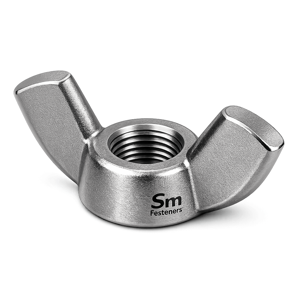
A wing nut is a threaded internally tapped fastener featuring two projecting wings enabling manual torque application without external tools.
Functional Characteristics
- Internal threaded fastener
- Symmetrical wing geometry
- Hand-applied tightening torque
- Reusable fastening interface
- Moderate preload capability
Unlike hex nuts, torque input is limited by ergonomic hand force.
Engineering Classification
| Parameter | Classification |
|---|---|
| Fastener Type | Internally Threaded Nut |
| Drive Method | Manual (Hand Tightening) |
| Load Category | Light to Moderate Clamping |
| Reusability | High |
| Installation Tool | Not Required |
1.3 Functional Role in Assemblies
Wing nuts are primarily applied where:
- Components require periodic removal.
- Alignment adjustments occur frequently.
- Fast assembly reduces downtime.
- Access restrictions prevent tool usage.
Typical assembly examples:
- Inspection covers
- Guarding systems
- Adjustable brackets
- Insulation blankets
- Jig & fixture assemblies
- Temporary structural positioning
1.4 Load Mechanics & Force Behavior
1.4.1 Torque–Tension Relationship
Clamping force generated by a wing nut follows the standard fastener equation:
Where:
- Fp = Preload Force (N)
- T = Applied Torque (N·m)
- K = Nut Factor
- D = Nominal Diameter (m)
Because torque is applied manually:
- Typical torque range: 2–15 N·m
- Preload values significantly lower than hex nuts.
1.4.2 Manual Torque Limitations
Human ergonomic limits govern performance.
| Thread Size | Typical Hand Torque |
|---|---|
| M4–M6 | 2–4 N·m |
| M8 | 5–7 N·m |
| M10 | 8–12 N·m |
| M12 | 10–15 N·m |
This limitation directly influences joint design.
1.4.3 Force Distribution
Wing geometry introduces:
- Non-uniform torque application
- Localized stress at wing root
- Increased bending stress
Therefore, wing nuts are not intended for structural primary load paths.
1.5 Joint Design Principles
Proper engineering design requires understanding wing nut limitations.
Recommended Design Conditions
✅ Frequent disassembly
✅ Low vibration environments
✅ Adjustable components
✅ Non-safety-critical joints
Avoid Using Wing Nuts When:
❌ High vibration exists
❌ Structural preload required
❌ Fatigue loading dominates
❌ High temperature creep risk exists
1.6 Thread Engagement Requirements
Minimum thread engagement:
For softer materials:
Ensures:
- Prevention of thread stripping
- Load transfer efficiency
- Long-term reusability
1.7 Friction & Nut Factor
Nut factor varies by surface condition.
| Condition | Nut Factor (K) |
|---|---|
| Dry Carbon Steel | 0.22–0.25 |
| Zinc Plated | 0.18–0.22 |
| Stainless Steel | 0.20–0.30 |
| Lubricated | 0.12–0.16 |
SM Fasteners validates coating friction performance through controlled process inspection aligned with ISO 9001 requirements.
1.8 Clamping Force Behaviour
Wing nuts create preload through:
- Thread flank friction (~40%)
- Bearing surface friction (~50%)
- Elastic bolt stretch (~10%)
Because applied torque is low:
- Joint relies heavily on proper washer selection.
- Hardened washers recommended.
1.9 Failure Mechanisms
1.9.1 Thread Stripping
Occurs when:
- Soft material used
- Insufficient engagement
- Over-tightening by tools
1.9.2 Wing Fracture
Caused by:
- Tool misuse
- Casting defects
- Poor grain flow
SM Fasteners employs forged manufacturing for superior grain continuity.
1.9.3 Fatigue Failure
Triggered by:
- Repeated loosening
- Vibration exposure
- Insufficient preload
Mitigation:
- Spring washers
- Nylon inserts
- Secondary locking devices
1.9.4 Corrosion-Induced Seizure
Common in stainless steel assemblies.
Control measures:
- Anti-seize compounds
- Controlled coating selection
- Dissimilar metal compatibility review
1.10 Mechanical Behavior Summary
| Property | Wing Nut Behavior |
|---|---|
| Preload Capability | Moderate |
| Installation Speed | Very High |
| Tool Requirement | None |
| Fatigue Resistance | Moderate |
| Vibration Resistance | Limited |
| Maintenance Suitability | Excellent |
2. PRODUCT TYPES, GEOMETRY, DIMENSIONAL LOGIC & INTERNATIONAL STANDARDS
2.1 Engineering Classification of Wing Nuts
Wing nuts are differentiated primarily by wing geometry, manufacturing method, load capacity, and compliance standard. Correct selection directly affects usability, fatigue resistance, and operator safety.
Within industrial procurement, wing nuts are categorized as functional-access fasteners, not structural load fasteners.
SM Fasteners manufactures wing nuts engineered for repeatable performance under controlled dimensional tolerances aligned with ISO 9001 quality systems.
2.2 Primary Wing Nut Types
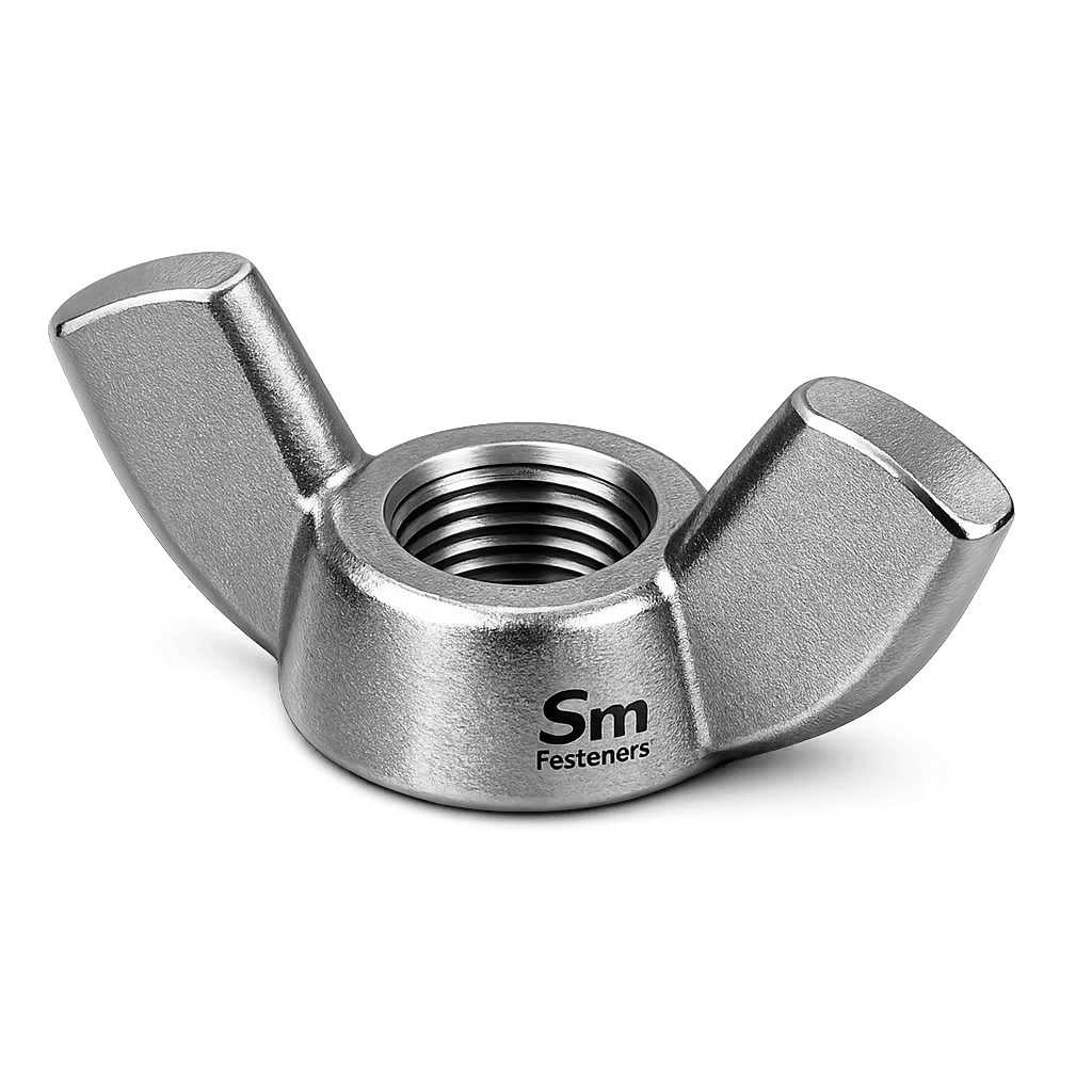
2.2.1 DIN 315 — Standard Wing Nut
Most widely specified industrial configuration.
Characteristics
- Symmetrical wings
- Ergonomic grip profile
- Hand tightening optimized
- Medium-duty clamping
Applications:
- Equipment covers
- Fixtures
- Insulation systems
- Machine guarding
2.2.2 DIN 314 — High Profile Wing Nut
Features extended wing height for improved leverage.
Engineering Advantages:
- Increased hand torque capacity
- Better use with gloves/PPE
- Suitable for outdoor maintenance work
Used in:
- Offshore access systems
- Power plant insulation
- Temporary structural assemblies
2.2.3 Heavy Pattern Wing Nut (Industrial Forged)
Enhanced section thickness.
Advantages:
- Higher fatigue resistance
- Reduced wing deformation
- Improved durability in repeated service
SM Fasteners offers custom heavy-pattern wing nuts for EPC project specifications.
2.2.4 Stainless Hygienic Wing Nuts
Designed for clean environments:
- Food processing
- Pharmaceutical plants
- Chemical handling systems
Features:
- Smooth radii
- Reduced contamination traps
- Electropolished surfaces
2.2.5 PEEK Wing Nuts (High-Performance Polymer)
Part of SM Fasteners’ advanced materials portfolio.
Properties:
- Electrical insulation
- Chemical resistance
- Non-galling threads
- Lightweight assemblies
Applications:
- Semiconductor equipment
- Medical systems
- Chemical reactors
- Non-magnetic assemblies
2.3 Geometry & Dimensional Logic
Wing nut geometry directly determines:
- Maximum achievable torque
- Operator grip efficiency
- Stress distribution
- Fatigue life
Key Geometric Parameters
| Parameter | Symbol | Function |
|---|---|---|
| Nominal Thread Size | d | Load transfer |
| Thread Pitch | P | Engagement control |
| Wing Span | e | Torque leverage |
| Overall Height | m | Thread engagement |
| Wing Thickness | t | Structural strength |
| Bearing Diameter | dc | Load distribution |
2.4 Dimensional Specification Table
(Typical DIN 315 Reference — Metric Series)
| Thread Size | Pitch (mm) | Height m (mm) | Wing Span e (mm) | Wing Thickness t (mm) | Approx Weight (g) |
|---|---|---|---|---|---|
| M4 | 0.7 | 8 | 18 | 2.0 | 2 |
| M5 | 0.8 | 10 | 22 | 2.5 | 4 |
| M6 | 1.0 | 12 | 26 | 3.0 | 7 |
| M8 | 1.25 | 16 | 33 | 4.0 | 15 |
| M10 | 1.5 | 20 | 45 | 5.0 | 28 |
| M12 | 1.75 | 24 | 55 | 6.0 | 45 |
| M16 | 2.0 | 32 | 70 | 8.0 | 90 |
| M20 | 2.5 | 40 | 85 | 10.0 | 160 |
(SM Fasteners weight charts supplied with batch documentation.)
2.5 Imperial Thread Dimensions
Used primarily for North American EPC projects.
| Size | UNC Pitch | UNF Pitch | Height (mm) | Wing Span (mm) |
|---|---|---|---|---|
| 1/4″ | 20 | 28 | 12 | 26 |
| 5/16″ | 18 | 24 | 14 | 30 |
| 3/8″ | 16 | 24 | 16 | 36 |
| 1/2″ | 13 | 20 | 20 | 45 |
| 5/8″ | 11 | 18 | 26 | 60 |
| 3/4″ | 10 | 16 | 32 | 75 |
2.6 Wing Geometry Engineering Considerations
Torque Leverage Relationship
Where:
- e = wing span
Increasing span increases achievable preload without tools.
Stress Concentration Zone
Critical design area:
- Wing root fillet radius
- Thread-to-body transition
- Bearing surface edge
SM Fasteners uses forged grain flow orientation to reduce stress risers.
2.7 Applicable International Standards
Wing nuts operate within multiple standards frameworks.
Dimensional Standards
| Standard | Scope |
|---|---|
| DIN 315 | Metric wing nuts |
| DIN 314 | High wing pattern |
| ISO 4035 (reference geometry principles) | Nut design |
| BS 84 | British threaded fasteners |
| ANSI B18.17 | Wing nut dimensions |
| ASME B1.1 | Unified threads |
Thread Standards & Tolerances
| Thread System | Standard | Tolerance Class |
|---|---|---|
| Metric Coarse | ISO 261 | 6H |
| Metric Fine | ISO 965 | 6H |
| UNC | ASME B1.1 | 2B |
| UNF | ASME B1.1 | 2B |
| BSW | BS 84 | Medium |
| BSF | BS 84 | Medium |
SM Fasteners supplies multi-standard compatibility for international projects.
2.8 Interchangeability Considerations
Engineering procurement must verify:
- Thread form compatibility
- Pitch equivalence
- Bearing face geometry
- Material property class
Improper interchangeability may cause:
- Galling
- Cross-threading
- Reduced preload
- Premature failure
2.9 Property Class & Strength Classification
Wing nuts are typically produced in moderate property classes due to manual torque application.
| Property Class | Typical Material | Use Case |
|---|---|---|
| Class 5 | Carbon Steel | General industrial |
| Class 6 | Medium carbon | Machinery |
| A2-70 | Stainless Steel | Corrosion environments |
| A4-80 | Marine/chemical | Offshore |
| Alloy Grades | Custom | High-temp service |
2.10 Mechanical Property Overview
| Grade | Proof Load (MPa) | Tensile Strength (MPa) | Hardness |
|---|---|---|---|
| Class 5 | 500 | 500–600 | 150–200 HB |
| Class 6 | 600 | 600–700 | 180–240 HB |
| A2-70 | 450 | 700 | ≤223 HB |
| A4-80 | 600 | 800 | ≤250 HB |
| Alloy Steel | 800+ | 900–1100 | Controlled |
2.11 Proof Load Capacity Table (Typical Engineering Values)
| Size | Class 5 (kN) | A2-70 (kN) | A4-80 (kN) |
|---|---|---|---|
| M6 | 5.2 | 4.6 | 5.5 |
| M8 | 9.5 | 8.5 | 10 |
| M10 | 15 | 13 | 16 |
| M12 | 22 | 20 | 24 |
| M16 | 40 | 36 | 43 |
| M20 | 63 | 56 | 68 |
(Values depend on engagement length and assembly design.)
2.12 Weight Chart — SM Fasteners Reference
| Size | Weight / Piece (g) | Weight / 100 pcs (kg) |
|---|---|---|
| M5 | 4 | 0.40 |
| M6 | 7 | 0.70 |
| M8 | 15 | 1.50 |
| M10 | 28 | 2.80 |
| M12 | 45 | 4.50 |
| M16 | 90 | 9.00 |
| M20 | 160 | 16.00 |
Weight verification provided within SM Fasteners inspection documentation.
2.13 Engineering Selection Logic
Correct wing nut selection requires evaluation of:
- Required preload
- Operator access
- Environment severity
- Maintenance frequency
- Material compatibility
- Thread standard compliance
Design Rule Summary
| Requirement | Recommended Choice |
|---|---|
| Frequent adjustment | DIN 315 |
| High leverage | DIN 314 |
| Corrosive environment | A4-80 Stainless |
| Chemical exposure | PEEK |
| Offshore service | Duplex Stainless |
| High temperature | Nickel alloys |
3. MATERIAL ENGINEERING, HEAT TREATMENT, MANUFACTURING WORKFLOW & SURFACE ENGINEERING
3.1 Materials Engineering Philosophy
Material selection is the primary engineering control governing wing nut performance.
Because wing nuts operate under:
- repetitive installation cycles,
- manual torque loading,
- environmental exposure,
- potential galvanic interaction,
the selected material must balance:
- Mechanical strength
- Corrosion resistance
- Galling resistance
- Manufacturability
- Lifecycle cost
SM Fasteners manufactures wing nuts across a full industrial alloy spectrum, supporting EPC, OEM, offshore, chemical, and infrastructure applications.
3.2 Industrial Material Range — SM Fasteners Capability
3.2.1 Carbon Steel
Most economical industrial option.
Typical Grades:
- ASTM A563 Grade A
- IS 1367 Class 5 / 6
- EN 10083 C35/C45
Characteristics:
- Good machinability
- Moderate strength
- Requires protective coating
Applications:
- Construction fixtures
- Temporary assemblies
- Equipment guarding
3.2.2 Alloy Steel
Used when higher mechanical integrity is required.
Typical Materials:
- ASTM A194 Gr.2H (adapted)
- 4140 / 42CrMo4
- EN 10269
Advantages:
- Higher fatigue resistance
- Better wear resistance
- Improved load retention
3.2.3 Stainless Steel
Primary industrial corrosion-resistant category.
A2 (304 Stainless Steel)
- General corrosion resistance
- Non-magnetic (annealed)
- Suitable for atmospheric environments
A4 (316 Stainless Steel)
- Molybdenum enhanced
- Superior chloride resistance
- Marine suitability
3.2.4 Duplex & Super Duplex Stainless Steel
Used in severe environments.
Grades:
- UNS S31803
- UNS S32205
- UNS S32750
Benefits:
- High strength
- Chloride SCC resistance
- Offshore compatibility
- Reduced section size possible
3.2.5 Nickel-Based Alloys
For extreme service conditions.
| Alloy | Key Advantage |
|---|---|
| Inconel 625 | High temperature + corrosion |
| Incoloy 825 | Acid resistance |
| Hastelloy C276 | Chemical process service |
| Monel 400 | Seawater resistance |
| SMO 254 | Pitting resistance |
Typical sectors:
- LNG
- Petrochemical reactors
- Offshore platforms
- Acid processing plants
3.2.6 PEEK Wing Nuts (High-Performance Polymer)
SM Fasteners manufactures engineered polymer fasteners for specialized applications.
Properties:
- Continuous service temp: ~260°C
- Electrical insulation
- Zero galvanic corrosion
- Chemical inertness
- Lightweight
Applications:
- Semiconductor manufacturing
- Medical equipment
- Chemical dosing systems
- MRI environments
3.3 Material Comparison Table
| Material | UTS (MPa) | Yield (MPa) | Corrosion Resistance | Temp Limit | Relative Cost | Typical Industry |
|---|---|---|---|---|---|---|
| Carbon Steel | 500–600 | 300 | Low | 300°C | Low | Construction |
| Alloy Steel | 800–1000 | 650 | Moderate | 450°C | Medium | Machinery |
| SS 304 (A2) | 700 | 450 | Good | 870°C | Medium | General Industry |
| SS 316 (A4) | 800 | 600 | Very Good | 925°C | Medium+ | Marine |
| Duplex | 900 | 650 | Excellent | 300°C | High | Offshore |
| Inconel 625 | 1000+ | 700 | Exceptional | 980°C | Very High | LNG |
| SMO 254 | 680 | 300 | Extreme | 400°C | High | Chemical |
| PEEK | — | — | Excellent | 260°C | High | Electronics |
3.4 Corrosion Resistance vs Environment
| Environment | Carbon Steel | SS304 | SS316 | Duplex | Nickel Alloy | PEEK |
|---|---|---|---|---|---|---|
| Indoor Industrial | ✓ | ✓ | ✓ | ✓ | ✓ | ✓ |
| Outdoor Atmosphere | Coated | ✓ | ✓ | ✓ | ✓ | ✓ |
| Marine/Seawater | ✗ | Limited | ✓ | ✓✓ | ✓✓ | ✓ |
| Acid Exposure | ✗ | Limited | Moderate | ✓ | ✓✓ | ✓✓ |
| H₂S Sour Service | ✗ | Limited | Controlled | ✓ | ✓✓ | ✓ |
| Chemical Processing | ✗ | Moderate | ✓ | ✓ | ✓✓ | ✓✓ |
✓✓ = Preferred engineering selection
3.5 NACE MR0175 / ISO 15156 Compliance
For Oil & Gas sour environments:
Engineering limits include:
- Controlled hardness
- Sulfide stress cracking resistance
- Approved alloy selection
SM Fasteners supplies compliant materials subject to:
- Heat treatment verification
- Hardness certification
- PMI confirmation
3.6 Heat Treatment Processes
Heat treatment controls:
- Strength
- Toughness
- Residual stress
- Fatigue life
3.6.1 Annealing
Purpose:
- Restore ductility
- Improve machinability
- Reduce internal stress
Applied to:
- Stainless steel
- Nickel alloys
3.6.2 Quench & Temper (Q&T)
Used for alloy steel wing nuts.
Process:
- Austenitizing
- Rapid quenching
- Tempering
Result:
- Increased tensile strength
- Controlled hardness
3.6.3 Solution Annealing (Stainless Steel)
Ensures:
- Corrosion resistance
- Carbide dissolution
- Uniform microstructure
Critical for A4 and duplex grades.
3.6.4 Age Hardening (Nickel Alloys)
Used where:
- High temperature strength required
- Creep resistance critical
Hardness Control Table
| Material | Max Hardness (HB) | Service Note |
|---|---|---|
| Carbon Steel | 200–240 | General duty |
| Alloy Steel | 250–320 | Heavy service |
| A2 Stainless | ≤223 | Prevent galling |
| A4 Stainless | ≤250 | Marine use |
| Duplex | ≤290 | NACE compliant |
3.7 End-to-End Manufacturing Workflow
SM Fasteners operates a traceable manufacturing chain compliant with ISO 9001 quality systems.
Step 1 — Raw Material Verification
Incoming inspection includes:
- Mill Test Certificate (MTC)
- Heat number verification
- Chemical analysis review
- Visual inspection
- Spectrochemical PMI (when required)
Step 2 — Forging / Forming
Preferred process: Hot Forging
Advantages:
- Continuous grain flow
- Improved fatigue resistance
- Superior wing strength
Alternative:
- Precision machining (small batches/custom alloys)
Step 3 — Trimming & Deburring
Ensures:
- Safe handling
- Uniform geometry
- Reduced stress concentrations
Step 4 — Thread Creation
Thread Rolling (Preferred)
Benefits:
- Cold-work strengthened threads
- Improved fatigue life
- Smooth surface finish
Thread Cutting
Used for:
- Large sizes
- Exotic alloys
- Low-volume production
Step 5 — Heat Treatment
Performed under controlled furnace calibration.
Documentation:
- Temperature charts
- Time records
- Hardness testing
Step 6 — Surface Preparation
Processes include:
- Shot blasting
- Pickling
- Passivation
- Ultrasonic cleaning
Step 7 — Coating / Surface Engineering
Applied according to service environment.
3.8 Surface Finish & Coating Technologies
Zinc Plating (Electroplated)
- Economical corrosion protection
- Indoor use
Risk:
- Hydrogen embrittlement (controlled baking required)
Hot Dip Galvanizing (HDG)
- Thick zinc layer
- Infrastructure applications
Thread allowance required due to coating thickness.
Mechanical Galvanizing
- Reduced hydrogen risk
- Uniform coating
PTFE / Xylan Coating
- Low friction
- Chemical resistance
- Anti-galling performance
Black Oxide
- Minimal corrosion protection
- Appearance + oil retention
Passivation (Stainless Steel)
Removes free iron and enhances chromium oxide layer.
Electropolishing
Used for:
- Hygienic applications
- Pharmaceutical service
3.9 Surface Finish Performance Comparison
| Finish | Corrosion Resistance | Friction Control | Appearance | Typical Use |
|---|---|---|---|---|
| Zinc Plated | Medium | Good | Bright | Indoor |
| HDG | High | Moderate | Matte | Structural |
| PTFE | High | Excellent | Colored | Chemical |
| Black Oxide | Low | Moderate | Black | Machinery |
| Passivated SS | High | Moderate | Metallic | Marine |
| Electropolished | Very High | Excellent | Mirror | Pharma |
3.10 Failure Prevention Through Surface Engineering
Major industrial risks mitigated:
| Failure Mode | Engineering Control |
|---|---|
| Galling | PTFE coating / lubrication |
| SCC | Proper alloy selection |
| Hydrogen Embrittlement | Mechanical coating / bake cycle |
| Fretting Corrosion | Surface lubrication |
| Seizure | Dissimilar metal review |
3.11 Manufacturing Traceability
Each SM Fasteners production lot maintains:
- Heat number traceability
- Process batch control
- Inspection records
- Coating certification
- Dimensional verification
Traceability supports EPC and third-party inspection requirements.
4. INSPECTION, QUALITY CONTROL, INDUSTRY APPLICATIONS, EXPORT CAPABILITY & COMPLETE ENGINEERING TABLES
4.1 Quality Assurance Philosophy — SM FASTENERS
Wing nuts used in industrial environments must demonstrate dimensional accuracy, material integrity, repeatability, and traceability.
SM Fasteners integrates inspection control within an ISO 9001 certified quality management system, ensuring each production batch meets international procurement and EPC audit requirements.
Quality assurance covers the entire lifecycle:
- Raw material verification
- Manufacturing validation
- Mechanical performance confirmation
- Surface integrity inspection
- Documentation traceability
4.2 Incoming Material Inspection
All production begins with controlled raw material verification.
Verification Activities
| Inspection | Method | Purpose |
|---|---|---|
| Material Certification | MTC Review | Chemical compliance |
| Heat Number Traceability | Marking verification | Full traceability |
| Chemical Analysis | Spectrometer PMI | Alloy confirmation |
| Visual Inspection | Surface check | Defect detection |
| Dimensional Stock Check | Calipers/Micrometer | Forging readiness |
SM Fasteners supplies EN 10204 3.1 or 3.2 certification upon project requirement.
4.3 In-Process Manufacturing Inspection
Quality control continues throughout manufacturing.
Process Control Points
- Forging temperature monitoring
- Tool wear inspection
- Thread gauge verification
- Heat treatment validation
- Coating thickness measurement
4.4 Dimensional Inspection
Wing nuts are verified against DIN/ISO tolerances.
Inspection Equipment
- Thread Plug Gauges (GO / NO-GO)
- Optical comparators
- Height gauges
- Surface plate inspection
- Coordinate Measuring Machine (CMM)
Dimensional Inspection Table
| Parameter | Standard | Inspection Method |
|---|---|---|
| Thread Pitch | ISO 261 | Thread gauge |
| Internal Thread Class | 6H | GO/NO-GO |
| Wing Span | DIN 315 | Vernier |
| Height | DIN 315 | Height gauge |
| Bearing Face Flatness | ISO 4759 | Surface plate |
4.5 Mechanical Testing
Mechanical validation confirms functional reliability.
| Test | Standard | Objective |
|---|---|---|
| Proof Load Test | ISO 898 | Load capacity |
| Tensile Verification | ASTM F606 | Strength validation |
| Hardness Testing | ISO 6508 | Heat treatment check |
| Torque Test | Internal procedure | Functional usability |
Mechanical Properties Table (Grade-Wise)
| Grade | Proof Strength (MPa) | Tensile Strength (MPa) | Hardness Limit |
|---|---|---|---|
| Class 5 | 500 | 500–600 | 200 HB |
| Class 6 | 600 | 600–700 | 240 HB |
| A2-70 | 450 | 700 | ≤223 HB |
| A4-80 | 600 | 800 | ≤250 HB |
| Duplex | 650 | 900 | ≤290 HB |
4.6 Non-Destructive Testing (NDT)
Applied based on project criticality.
| Method | Purpose |
|---|---|
| Visual Inspection (VT) | Surface defects |
| Magnetic Particle (MPI) | Crack detection |
| Dye Penetrant (PT) | Surface discontinuities |
| Ultrasonic Testing | Internal defects (large forgings) |
4.7 Positive Material Identification (PMI)
PMI ensures alloy correctness.
Used for:
- Duplex stainless steel
- Nickel alloys
- NACE compliant projects
- Offshore supplies
Equipment:
- Portable XRF analyzer
4.8 Surface Coating Inspection
| Inspection | Requirement |
|---|---|
| Coating Thickness | Micron verification |
| Adhesion Test | Coating durability |
| Salt Spray Test | ASTM B117 corrosion resistance |
| Passivation Validation | ASTM A967 |
4.9 Failure Mechanism Control — Inspection Perspective
| Failure Mode | Inspection Control |
|---|---|
| Thread Stripping | Thread gauge verification |
| Galling | Surface finish inspection |
| Hydrogen Embrittlement | Post-plating bake records |
| SCC Risk | Hardness control |
| Fatigue Crack | MPI / PT |
4.10 Industrial Applications Mapping
Wing nuts support maintenance-access assemblies across global industries.
Construction & Structural Steel
Applications:
- Formwork retention
- Temporary bracing
- Scaffolding accessories
- Adjustment fixtures
Requirement:
- Rapid installation
- Reusability
Oil & Gas Industry
Upstream
- Instrument covers
- Control panel mounting
Midstream
- Pipeline insulation clamps
- Valve identification assemblies
Downstream
- Access doors
- Filter housing covers
Materials:
- A4 stainless
- Duplex
- NACE compliant alloys
Power Generation
- Turbine insulation blankets
- Cable tray fixtures
- Maintenance guarding
- Boiler access panels
Petrochemical & Chemical Processing
Preferred materials:
- SS316
- SMO 254
- Hastelloy
- PEEK fasteners
Benefits:
- Chemical resistance
- Anti-seizing behavior
LNG & Offshore Platforms
Critical requirements:
- Chloride resistance
- Non-galling threads
- Corrosion reliability
SM Fasteners supplies duplex and nickel alloy wing nuts meeting offshore specifications.
Automotive & Heavy Equipment
- Tool-less inspection access
- Calibration brackets
- Adjustable mounts
Railways & Infrastructure
- Electrical panel fixing
- Signage systems
- Maintenance access panels
Shipbuilding & Marine
- Deck equipment covers
- Lighting mounts
- Serviceable enclosures
PEEK Wing Nut Applications
| Industry | Use Case |
|---|---|
| Semiconductor | Non-contaminating assemblies |
| Medical | MRI-safe fastening |
| Chemical | Corrosion-free adjustment |
| Electronics | Electrical insulation |
4.11 Tightening Torque Chart (Engineering Guidance)
(Hand-tightened values — typical reference)
| Size | Grade | Dry Torque (N·m) | Lubricated (N·m) |
|---|---|---|---|
| M6 | Class 5 | 3 | 2.5 |
| M8 | Class 5 | 6 | 5 |
| M10 | Class 6 | 10 | 8 |
| M12 | Class 6 | 14 | 11 |
| M16 | A2-70 | 20 | 16 |
| M20 | A4-80 | 30 | 24 |
(Manual tightening limits apply.)
4.12 Preload Calculation — Engineering Example
Formula
Where:
- Torque T = 10 N·m
- Nut factor K = 0.20
- Diameter D = 0.01 m (M10)
Result: Approximate clamping force = 5 kN
4.13 Thread Standards & Tolerances Table
| Thread Type | Standard | Tolerance |
|---|---|---|
| Metric Coarse | ISO 261 | 6H |
| Metric Fine | ISO 965 | 6H |
| UNC | ASME B1.1 | 2B |
| UNF | ASME B1.1 | 2B |
| BSW | BS 84 | Medium |
| BSF | BS 84 | Medium |
4.14 Proof Load & Tensile Capacity Table
| Size | Proof Load (kN) | Tensile Capacity (kN) |
|---|---|---|
| M6 | 5 | 7 |
| M8 | 9 | 13 |
| M10 | 15 | 21 |
| M12 | 22 | 30 |
| M16 | 40 | 55 |
| M20 | 63 | 85 |
4.15 Surface Finish Performance Matrix
| Coating | Corrosion Protection | Galling Resistance | Typical Industry |
|---|---|---|---|
| Zinc Plated | Medium | Moderate | Indoor machinery |
| HDG | High | Moderate | Infrastructure |
| PTFE/Xylan | Very High | Excellent | Chemical |
| Passivated SS | High | Good | Marine |
| Electropolished | Very High | Excellent | Pharma |
4.16 Corrosion Resistance vs Environment
| Environment | Recommended Material |
|---|---|
| Atmospheric | SS304 |
| Marine | SS316 / Duplex |
| Acidic | Hastelloy |
| H₂S | Duplex / Nickel Alloy |
| High Temperature | Inconel |
| Chemical Exposure | PEEK |
4.17 Weight Chart — SM Fasteners Reference
| Size | Weight/Piece (g) | Weight/100 pcs (kg) |
|---|---|---|
| M5 | 4 | 0.40 |
| M6 | 7 | 0.70 |
| M8 | 15 | 1.50 |
| M10 | 28 | 2.80 |
| M12 | 45 | 4.50 |
| M16 | 90 | 9.00 |
| M20 | 160 | 16.00 |
Weight conformity verified within inspection documentation.
4.18 Export Packaging & Logistics
SM Fasteners provides project-grade export preparation.
Industrial Packaging
- VCI corrosion protection
- Thread protection caps
- Heat-number labeling
- Moisture barrier bags
- Batch identification
Export Crating
- ISPM-15 fumigated wooden crates
- Palletized loads
- Container optimization
- Shock-resistant packing
4.19 Documentation Package (Global EPC Supply)
Each shipment may include:
| Document | Purpose |
|---|---|
| Mill Test Certificate | Material verification |
| Heat Treatment Report | Mechanical confirmation |
| Dimensional Inspection Report | Compliance proof |
| Coating Certificate | Surface validation |
| PMI Report | Alloy confirmation |
| Certificate of Conformity | Order compliance |
| Packing List | Logistics control |
| EN 10204 3.1 / 3.2 | Third-party acceptance |
4.20 Integration with ISO 9001 Quality System
SM Fasteners ensures:
- Controlled procedures
- Calibration management
- Document traceability
- Continuous improvement
- Audit readiness for EPC qualification
Engineering Summary — Wing Nut Systems
Wing nuts represent a specialized fastening solution optimized for:
- Rapid maintenance access
- Tool-free assembly
- Controlled clamping applications
- Repetitive service environments
Through:
- advanced metallurgy,
- precision forging,
- controlled manufacturing,
- rigorous inspection,
- certified quality systems,
SM Fasteners delivers wing nuts aligned with international engineering expectations and global procurement standards.