
Nickel Grades 800 / 800H / 825 / DS
1. Introduction to Nickel Alloy Fasteners
Nickel alloy fasteners are specialized engineered fastening components designed for service conditions where conventional stainless steel or alloy steel fasteners may experience corrosion degradation, elevated-temperature strength loss, stress corrosion cracking, or aggressive chemical attack.
Among industrial nickel-based materials, the following grades are extensively utilized:
| Grade | UNS Number | Material Family | Typical Application |
|---|---|---|---|
| Incoloy 800 | N08800 | Nickel-Iron-Chromium Alloy | High-temperature equipment |
| Incoloy 800H | N08810 | Controlled Carbon High Temperature Alloy | Creep-resistant service |
| Incoloy 825 | N08825 | Nickel-Iron-Chromium-Molybdenum Alloy | Chemical processing |
| Nickel DS (Double Strength) | Proprietary/Industry Designation | High Strength Nickel Alloy | Severe industrial duty |
These alloys are selected where:
- Elevated temperatures exceed stainless steel capabilities
- Sulfur-bearing atmospheres are present
- Chloride contamination exists
- Acidic chemical exposure occurs
- Long-term creep resistance is required
- Thermal cycling causes differential expansion stresses
- Offshore and petrochemical environments demand superior corrosion resistance
2. Technical Definition of Nickel Alloy Fasteners
Nickel alloy fasteners are threaded mechanical joining elements manufactured from nickel-based alloys containing carefully controlled amounts of:
- Nickel (Ni)
- Chromium (Cr)
- Iron (Fe)
- Molybdenum (Mo)
- Titanium (Ti)
- Aluminum (Al)
- Copper (Cu)
The alloying system creates:
High Temperature Stability
Protective chromium oxide layers remain stable at temperatures where ordinary steels oxidize rapidly.
Corrosion Resistance
Nickel improves resistance to:
- Sulfuric acid
- Phosphoric acid
- Nitric acid
- Chlorides
- Caustic media
- Sour gas environments
Mechanical Integrity
The alloys maintain:
- Tensile strength
- Yield strength
- Ductility
- Fatigue resistance
during prolonged exposure to elevated temperatures.
3. Chemical Composition Overview
Incoloy 800
| Element | Typical % |
|---|---|
| Nickel | 30–35 |
| Chromium | 19–23 |
| Iron | Balance |
| Carbon | ≤0.10 |
| Aluminum | 0.15–0.60 |
| Titanium | 0.15–0.60 |
Incoloy 800H
| Element | Typical % |
|---|---|
| Nickel | 30–35 |
| Chromium | 19–23 |
| Iron | Balance |
| Carbon | 0.05–0.10 |
| Aluminum + Titanium | Controlled |
The higher carbon content promotes superior creep rupture strength.
Incoloy 825
| Element | Typical % |
|---|---|
| Nickel | 38–46 |
| Chromium | 19.5–23.5 |
| Iron | Balance |
| Molybdenum | 2.5–3.5 |
| Copper | 1.5–3.0 |
| Titanium | 0.6–1.2 |
Nickel DS
| Element | Range |
|---|---|
| Nickel | High |
| Chromium | Moderate |
| Molybdenum | Variable |
| Iron | Controlled |
| Strengthening Elements | Proprietary |
Used where enhanced mechanical properties beyond standard nickel alloys are required.
4. Functional Role of Nickel Alloy Fasteners
Fasteners perform a critical structural function:
Primary Functions
- Clamp components together
- Transfer load
- Resist vibration loosening
- Maintain gasket compression
- Preserve structural alignment
- Accommodate thermal expansion
In industrial systems, failure of a single fastener can result in:
- Pressure leakage
- Equipment shutdown
- Production loss
- Safety incidents
- Environmental release
Consequently, material selection is considered a critical engineering decision rather than a procurement-only activity.
5. Fastener Load Mechanics
Understanding load mechanics is essential when specifying Nickel Alloy 800/800H/825/DS fasteners.
The primary loads acting on fasteners include:
Tensile Load
Acts along the bolt axis.
Examples:
- Flanged joints
- Pressure vessels
- Structural connections
Shear Load
Acts perpendicular to bolt axis.
Examples:
- Pipe supports
- Structural frames
- Equipment mounting systems
Combined Loading
Most industrial joints experience both tensile and shear stresses simultaneously.
Cyclic Loading
Repeated load fluctuations generate fatigue stresses.
Examples:
- Compressors
- Pumps
- Turbines
- Rotating machinery
6. Preload Fundamentals
A properly tightened fastener develops preload.
Preload is the intentional tensile force induced in a fastener during tightening.
The preload creates clamping force that holds assembled components together.
Relationship:
The objective is:
- Prevent joint separation
- Prevent vibration loosening
- Maintain gasket compression
- Reduce fatigue loading
Insufficient preload causes:
- Leakage
- Joint movement
- Fatigue cracking
Excessive preload causes:
- Thread stripping
- Yielding
- Galling
- Premature failure
7. Preload Calculation Formula
The standard engineering relationship:
Where:
| Symbol | Definition |
|---|---|
| F | Recommended preload |
| As | Tensile stress area |
| Sy | Yield strength |
Worked Example
M20 Incoloy 825 Bolt
Assumptions:
| Parameter | Value |
|---|---|
| Diameter | 20 mm |
| Stress Area | 245 mm² |
| Yield Strength | 220 MPa |
Calculation:
Recommended preload:40.4kN
This preload provides sufficient clamping force while maintaining an adequate safety margin below yielding.
8. Torque-Tension Relationship
Torque applied to a bolt is converted into preload.
However, approximately:
| Energy Distribution | Percentage |
|---|---|
| Thread friction | 40% |
| Bearing friction | 50% |
| Useful preload | 10% |
Thus:
Where:
| Variable | Description |
|---|---|
| T | Torque |
| K | Nut factor |
| F | Preload |
| D | Nominal diameter |
Factors affecting torque:
- Lubrication
- Surface finish
- Coating type
- Thread quality
- Material hardness
Nickel alloys often require controlled lubrication to minimize galling.
9. Force Transfer Mechanisms
Friction-Type Joint
Load transferred by:
- Clamping force
- Surface friction
Common in:
- Structural steel
- Pressure vessel flanges
Advantages:
- Reduced bolt shear
- Improved fatigue life
Bearing-Type Joint
Load transferred through:
- Bolt shank
- Hole contact
Common in:
- Structural assemblies
- Machinery supports
Advantages:
- Higher load capacity
Disadvantages:
- Increased bolt stress
10. Joint Design Principles
Proper joint design ensures fastener reliability.
Key engineering considerations include:
Material Compatibility
Fastener material should match or exceed parent material corrosion resistance.
Examples:
| Base Material | Recommended Fastener |
|---|---|
| Incoloy Equipment | Incoloy 800 |
| Acid Process Equipment | Incoloy 825 |
| High Temperature Furnace | 800H |
| Offshore Nickel Systems | Nickel DS |
Joint Stiffness
A stiffer joint experiences:
- Less relaxation
- Better preload retention
- Improved fatigue resistance
Thread Engagement
Minimum thread engagement:
| Material | Engagement |
|---|---|
| Steel | 1 × Diameter |
| Nickel Alloy | 1–1.5 × Diameter |
| Soft Alloy | 1.5–2 × Diameter |
Thermal Expansion
Nickel alloys exhibit favorable thermal stability.
Typical coefficient:
| Material | µm/m°C |
|---|---|
| Carbon Steel | 12 |
| Stainless Steel | 17 |
| Incoloy 800 | 14 |
| Incoloy 825 | 14.5 |
This reduces thermal stress mismatch in elevated-temperature assemblies.
11. Fatigue Behavior of Nickel Alloy Fasteners
Fatigue failure accounts for a significant proportion of industrial fastener failures.
The process involves:
- Crack initiation
- Crack propagation
- Final fracture
Fatigue is accelerated by:
- Insufficient preload
- Surface defects
- Corrosion attack
- Stress concentration
- Vibration
Nickel alloys demonstrate superior fatigue resistance compared to many conventional steels due to:
- High ductility
- Stable microstructure
- Corrosion resistance
12. Stress Concentration Effects
Highest stresses occur at:
- First engaged thread
- Thread roots
- Head-to-shank transition
- Under-head fillet
Engineering controls include:
- Rolled threads
- Proper radii
- Controlled machining
- Surface finishing
SM Fasteners employs controlled manufacturing processes to minimize stress raisers and enhance fatigue performance in critical industrial applications.
13. Creep Resistance in Elevated Temperature Service
Creep is time-dependent deformation occurring under sustained load.
Critical for:
- Furnaces
- Reformers
- Boilers
- Heat exchangers
- Thermal reactors
Temperature Threshold
| Material | Creep Concern Begins |
|---|---|
| Carbon Steel | 370°C |
| Stainless Steel | 500°C |
| Incoloy 800 | 600°C+ |
| Incoloy 800H | 650°C+ |
800H was specifically developed for creep-resistant applications.
14. Elevated Temperature Load Retention
At high temperatures, conventional fasteners lose strength.
Nickel alloy fasteners retain:
- Yield strength
- Tensile strength
- Oxidation resistance
over extended operating periods.
This makes them suitable for:
- Ethylene crackers
- Heat treatment furnaces
- Petrochemical heaters
- Waste heat recovery systems
15. Corrosion-Assisted Load Degradation
Mechanical loads interact with corrosive environments.
Common degradation mechanisms include:
Pitting Corrosion
Localized attack causing stress concentration.
Crevice Corrosion
Occurs beneath gaskets and washers.
Stress Corrosion Cracking
Simultaneous:
- Tensile stress
- Corrosive medium
Hydrogen Damage
Can affect high-strength alloys.
Nickel-based alloys generally provide superior resistance compared with standard stainless steels.
16. Galvanic Considerations
When dissimilar metals contact in conductive environments, galvanic corrosion may occur.
Engineering recommendations:
| Component Material | Fastener Recommendation |
|---|---|
| Nickel Alloy | Nickel Alloy |
| Duplex Stainless | Duplex/Nickel |
| Carbon Steel | Isolated Fastener |
| Aluminum | Insulated Joint |
Proper isolation prevents accelerated corrosion.
17. Reliability Engineering Perspective
For EPC projects and critical industrial assets, fastener selection should be based on:
Mechanical Requirements
- Tensile load
- Shear load
- Fatigue load
Environmental Requirements
- Temperature
- Corrosion
- Pressure
Inspection Requirements
- Traceability
- Testing
- Certification
Lifecycle Cost
Lowest purchase cost rarely corresponds to lowest lifecycle cost.
Nickel Alloy 800, 800H, 825, and DS fasteners are frequently selected because reduced maintenance, improved reliability, and extended service life offset higher initial material costs.
18. Engineering Selection Summary
| Requirement | 800 | 800H | 825 | DS |
|---|---|---|---|---|
| Oxidation Resistance | Excellent | Excellent | Very Good | Excellent |
| High Temperature | Excellent | Outstanding | Moderate | High |
| Chemical Resistance | Good | Good | Excellent | Excellent |
| Sulfuric Acid Service | Moderate | Moderate | Excellent | Excellent |
| Creep Resistance | High | Very High | Moderate | High |
| Pressure Equipment | Excellent | Excellent | Excellent | Excellent |
| Offshore Service | Good | Good | Excellent | Excellent |
19. Product Forms Manufactured in Nickel Grades 800 / 800H / 825 / DS
Industrial nickel alloy fasteners are manufactured in a broad range of geometries to accommodate varying load conditions, assembly requirements, maintenance access constraints, pressure-retaining joints, and corrosion environments.
SM Fasteners manufactures precision-engineered fasteners in Nickel Alloy 800, 800H, 825, and DS grades for EPC, OEM, petrochemical, power generation, offshore, and heavy engineering applications.
Standard Product Portfolio
| Product Type | Typical Standards |
|---|---|
| Hex Bolts | ISO 4014, DIN 931 |
| Hex Cap Screws | ISO 4017, DIN 933 |
| Heavy Hex Bolts | ASTM A193 |
| Socket Head Cap Screws | ISO 4762, DIN 912 |
| Stud Bolts | ASTM A193/A320 |
| Threaded Rods | DIN 975, DIN 976 |
| Hex Nuts | ISO 4032, DIN 934 |
| Heavy Hex Nuts | ASTM A194 |
| Lock Nuts | DIN 985 |
| Jam Nuts | DIN 439 |
| Plain Washers | ISO 7089, DIN 125 |
| Heavy Duty Washers | ASTM F436 |
| Spring Washers | DIN 127 |
| Retaining Rings | DIN 471, DIN 472 |
| Custom Fasteners | Project Specific |
20. Hex Bolts
Hex bolts remain the most widely used industrial fastening solution.
Characteristics
- Six-sided head
- External wrench engagement
- High torque transmission capability
- Suitable for structural and pressure applications
Typical Applications
- Structural steel assemblies
- Heat exchangers
- Pressure vessels
- Pump skids
- Pipe supports
- Turbine systems
Advantages
- High preload capability
- Easy field maintenance
- Broad dimensional standardization
- Excellent interchangeability
21. Heavy Hex Bolts
Heavy hex bolts feature increased head dimensions compared with standard hex bolts.
Benefits
- Increased wrenching area
- Better load distribution
- Improved high-temperature performance
- Reduced bearing stress
Common in:
- Petrochemical plants
- Refineries
- Offshore platforms
- Boiler systems
- Pressure vessel flanges
22. Stud Bolt
Stud bolts are fully threaded rods used with two nuts.
Advantages
- Uniform load distribution
- Better gasket compression
- Easier maintenance
- Improved flange alignment
Typical Usage
| Industry | Application |
|---|---|
| Oil & Gas | Flanges |
| LNG | Cryogenic piping |
| Petrochemical | Pressure vessels |
| Power Plants | Steam systems |
| Offshore | Process piping |
23. Threaded Rods
Threaded rods provide continuous thread engagement over the full length.
Typical Functions
- Structural anchoring
- Pipe supports
- Equipment mounting
- Hanger systems
Advantages
- Adjustable positioning
- Long-span fastening
- High flexibility
Available in:
- Metric thread
- UNC
- UNF
- Custom threads
24. Socket head cap screws
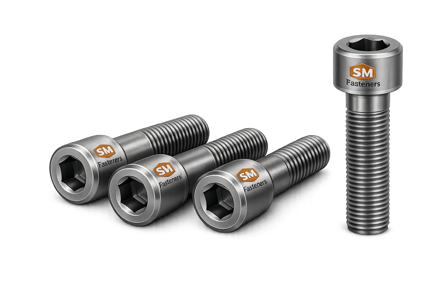
Socket head screws provide high-strength fastening where access space is limited.
Features
- Internal hex drive
- Cylindrical head
- Precision alignment capability
Applications
- Turbomachinery
- OEM equipment
- Instrumentation systems
- Compact assemblies
25. Nickel Alloy Nuts
Nuts provide thread engagement and preload retention.
Common Types
| Nut Type | Function |
|---|---|
| Hex Nut | General fastening |
| Heavy Hex Nut | High load applications |
| Lock Nut | Vibration resistance |
| Jam Nut | Secondary locking |
| Slotted Nut | Mechanical locking |
| Coupling Nut | Rod joining |
Nickel alloy nuts are commonly paired with matching alloy bolts to eliminate galvanic compatibility concerns.
26. Industrial Washers
Washers perform several engineering functions.
Functions
- Load distribution
- Surface protection
- Reduction of embedding
- Improved preload retention
Types
| Washer Type | Purpose |
|---|---|
| Plain Washer | General load distribution |
| Heavy Washer | Structural loads |
| Spring Washer | Vibration resistance |
| Belleville Washer | Thermal compensation |
| Spherical Washer | Misalignment correction |
27. Retaining Rings & Specialty Components
Nickel alloy retaining rings are utilized where corrosion resistance and elevated-temperature capability are required.
Applications include:
- Turbines
- Compressors
- Valves
- Rotating equipment
SM Fasteners also manufactures:
- U-bolts
- Eye bolts
- Foundation bolts
- Anchor bolts
- Special forgings
- CNC-machined fasteners
- PEEK fastener assemblies for electrically isolated systems
28. Fastener Geometry Fundamentals
Fastener geometry directly influences:
- Strength
- Fatigue resistance
- Torque transmission
- Preload retention
Critical dimensions include:
| Parameter | Description |
|---|---|
| d | Nominal Diameter |
| P | Thread Pitch |
| k | Head Height |
| s | Width Across Flats |
| e | Width Across Corners |
| b | Thread Length |
| L | Overall Length |
29. Metric Thread Geometry
Metric threads follow ISO standards.
Designation:
Example:
M20 × 2.5 × 100
Where:
| Element | Meaning |
|---|---|
| M | Metric thread |
| 20 | Nominal diameter |
| 2.5 | Pitch |
| 100 | Length |
30. Standard Metric Thread Pitch Table
| Size | Coarse Pitch (mm) | Fine Pitch (mm) |
|---|---|---|
| M6 | 1.0 | 0.75 |
| M8 | 1.25 | 1.0 |
| M10 | 1.5 | 1.25 |
| M12 | 1.75 | 1.5 |
| M16 | 2.0 | 1.5 |
| M20 | 2.5 | 1.5 |
| M24 | 3.0 | 2.0 |
| M30 | 3.5 | 2.0 |
| M36 | 4.0 | 3.0 |
| M42 | 4.5 | 3.0 |
| M48 | 5.0 | 3.0 |
31. Unified Thread Systems (UNC/UNF)
Used extensively in:
- ASME equipment
- Oil & Gas projects
- North American standards
UNC
Unified National Coarse
Advantages:
- Rapid assembly
- Better contamination tolerance
UNF
Unified National Fine
Advantages:
- Higher preload capability
- Improved vibration resistance
32. UNC Thread Table
| Diameter | UNC TPI |
|---|---|
| 1/4″ | 20 |
| 5/16″ | 18 |
| 3/8″ | 16 |
| 1/2″ | 13 |
| 5/8″ | 11 |
| 3/4″ | 10 |
| 7/8″ | 9 |
| 1″ | 8 |
| Diameter | UNF TPI |
|---|---|
| 1/4″ | 28 |
| 5/16″ | 24 |
| 3/8″ | 24 |
| 1/2″ | 20 |
| 5/8″ | 18 |
| 3/4″ | 16 |
| 7/8″ | 14 |
| 1″ | 12 |
34. British Thread Standards
British thread systems remain common in legacy infrastructure and maintenance projects.
BSW
British Standard Whitworth
55° thread angle
BSF
British Standard Fine
55° thread angle
Used in:
- Railways
- Marine systems
- Legacy industrial assets
35. Thread Standards & Tolerance Table
Mandatory Engineering Table
| Thread System | Standard | Thread Angle | Typical Tolerance |
|---|---|---|---|
| Metric Coarse | ISO 261 | 60° | 6g / 6H |
| Metric Fine | ISO 261 | 60° | 6g / 6H |
| UNC | ASME B1.1 | 60° | 2A / 2B |
| UNF | ASME B1.1 | 60° | 2A / 2B |
| BSW | BS 84 | 55° | Medium |
| BSF | BS 84 | 55° | Medium |
| NPT | ASME B1.20.1 | 60° | Pipe Taper |
| BSPT | ISO 7 | 55° | Pipe Taper |
36. Dimensional Logic for Hex Bolts
Hex bolt dimensions are governed by standard proportions to ensure interchangeability.
Example Dimensions
| Size | Across Flats s (mm) | Head Height k (mm) |
|---|---|---|
| M8 | 13 | 5.3 |
| M10 | 16 | 6.4 |
| M12 | 18 | 7.5 |
| M16 | 24 | 10 |
| M20 | 30 | 12.5 |
| M24 | 36 | 15 |
| M30 | 46 | 18.7 |
| M36 | 55 | 22.5 |
37. Dimensional Specification Table
Mandatory Engineering Table
| Size | Pitch | Head Width | Head Height | Length Range |
|---|---|---|---|---|
| M6 | 1.0 | 10 mm | 4 mm | 10–150 mm |
| M8 | 1.25 | 13 mm | 5.3 mm | 12–200 mm |
| M10 | 1.5 | 16 mm | 6.4 mm | 16–300 mm |
| M12 | 1.75 | 18 mm | 7.5 mm | 20–300 mm |
| M16 | 2.0 | 24 mm | 10 mm | 25–400 mm |
| M20 | 2.5 | 30 mm | 12.5 mm | 30–500 mm |
| M24 | 3.0 | 36 mm | 15 mm | 40–500 mm |
| M30 | 3.5 | 46 mm | 18.7 mm | 50–600 mm |
| M36 | 4.0 | 55 mm | 22.5 mm | 60–800 mm |
38. Thread Engagement Design Rules
Recommended minimum engagement:
| Material Combination | Engagement |
|---|---|
| Steel to Steel | 1D |
| Nickel to Nickel | 1.25D |
| Nickel to Stainless | 1.25D |
| Nickel to Aluminum | 2D |
| Nickel to Cast Iron | 1.5D |
D = nominal diameter
39. Pressure Vessel Fastening Requirements
Pressure-retaining equipment often requires:
- Heavy hex bolts
- Heavy hex nuts
- Full material traceability
- Certified heat numbers
Applicable standards:
- ASME BPVC
- ASTM A193
- ASTM A194
- ASME PCC-1
Nickel Alloy 800H and 825 are frequently specified for these environments.
40. International Standards Applicable to Nickel Alloy Fasteners
ISO Standards
| Standard | Description |
|---|---|
| ISO 898 | Mechanical properties |
| ISO 4014 | Hex bolts |
| ISO 4017 | Hex screws |
| ISO 4032 | Hex nuts |
| ISO 7089 | Plain washers |
| ISO 965 | Thread tolerances |
| ISO 3506 | Corrosion-resistant fasteners |
DIN Standards
| Standard | Description |
|---|---|
| DIN 931 | Hex bolt partial thread |
| DIN 933 | Fully threaded hex bolt |
| DIN 934 | Hex nut |
| DIN 125 | Plain washer |
| DIN 127 | Spring washer |
| DIN 912 | Socket head cap screw |
| DIN 975 | Threaded rod |
| DIN 976 | Stud bolts |
ASTM Standards
| Standard | Application |
|---|---|
| ASTM A193 | Alloy bolting materials |
| ASTM A194 | High-temperature nuts |
| ASTM F436 | Hardened washers |
| ASTM B408 | Nickel alloy bars |
| ASTM B425 | Nickel alloy rods |
| ASTM B564 | Nickel alloy forgings |
| ASTM E8 | Tensile testing |
| ASTM E18 | Hardness testing |
British Standards
| Standard | Application |
|---|---|
| BS 3692 | Fastener dimensions |
| BS 4190 | Hex bolts |
| BS 1083 | Stud bolts |
| BS 4320 | Washers |
| BS 84 | Whitworth threads |
41. Interchangeability Considerations
Global EPC projects often require dimensional interchangeability.
Key factors include:
Must Match
- Diameter
- Pitch
- Thread form
- Strength level
- Material grade
Verify Before Replacement
- Head dimensions
- Nut height
- Coating thickness
- Operating temperature
- Corrosion environment
Failure to verify interchangeability can result in:
- Incorrect preload
- Leakage
- Galling
- Fatigue failure
42. Fastener Selection Matrix
| Service Condition | Recommended Grade |
|---|---|
| Furnace Equipment | 800H |
| Steam Reformer | 800H |
| Heat Exchanger | 800 |
| Sulfuric Acid Plant | 825 |
| Phosphoric Acid Plant | 825 |
| Offshore Systems | 825 / DS |
| Chemical Processing | 825 |
| Pressure Vessel | 800H |
| LNG Process Equipment | 825 |
| Heavy Industrial Duty | DS |
43. Engineering Design Summary
Selection of Nickel Alloy 800, 800H, 825, and DS fasteners must consider:
- Load path
- Joint geometry
- Thread engagement
- Thermal expansion
- Corrosion environment
- Applicable international standards
- Inspection and certification requirements
Dimensional compliance with ISO, ASTM, DIN, and BS standards ensures interchangeability, maintainability, and procurement consistency across global industrial projects.
44. Material Selection Philosophy for Industrial Fasteners
Material selection is one of the most critical engineering decisions in fastener design. The selected alloy must satisfy mechanical loading requirements while simultaneously resisting corrosion, thermal degradation, creep, oxidation, and environmental cracking mechanisms throughout the intended service life.
For EPC projects, pressure-retaining equipment, and critical infrastructure, fastener material selection should consider:
Mechanical Requirements
- Tensile strength
- Yield strength
- Fatigue resistance
- Impact resistance
- Creep resistance
Environmental Requirements
- Atmospheric exposure
- Chloride contamination
- Acid service
- H₂S exposure
- Offshore environments
- Elevated temperature operation
Regulatory Requirements
- ASTM compliance
- ASME compliance
- NACE MR0175
- ISO 15156
- Client project specifications
45. Nickel Alloy 800 (UNS N08800)
Material Overview
Incoloy 800 is a nickel-iron-chromium alloy developed for high-temperature oxidation and carburization resistance.
Key Characteristics
- Excellent oxidation resistance
- Stable microstructure
- Good strength retention
- Resistance to thermal cycling
- Resistance to carburizing atmospheres
Typical Service Temperature
| Condition | Temperature |
|---|---|
| Continuous Service | Up to 870°C |
| Intermittent Service | Up to 980°C |
Common Applications
- Heat exchangers
- Industrial furnaces
- Petrochemical heaters
- Boiler components
- Steam systems
46. Nickel Alloy 800H (UNS N08810)
Material Overview
Incoloy 800H is a modified version of Alloy 800 with controlled carbon content and grain size.
Advantages Over 800
- Improved creep resistance
- Superior stress rupture strength
- Better high-temperature stability
Recommended For
- Steam reformers
- Ethylene cracking units
- Furnace construction
- High-temperature reactors
Typical Temperature Capability
| Service | Temperature |
|---|---|
| Continuous | 900°C |
| Peak Exposure | 1100°C |
47. Nickel Alloy 825 (UNS N08825)
Material Overview
Alloy 825 incorporates molybdenum, copper, and titanium additions to improve corrosion resistance.
Primary Benefits
- Sulfuric acid resistance
- Phosphoric acid resistance
- Chloride SCC resistance
- Pitting resistance
- Crevice corrosion resistance
Typical Applications
- Chemical plants
- Offshore platforms
- LNG facilities
- Desalination systems
- Pollution control equipment
48. Nickel DS Alloy
Nickel DS (Double Strength) fasteners are generally specified where enhanced mechanical performance is required beyond conventional nickel alloy bolting.
Typical requirements include:
- Higher preload capability
- Improved fatigue resistance
- Severe service operation
- High-pressure systems
- Critical rotating equipment
Exact composition and mechanical properties may vary according to project specifications and manufacturing requirements.
49. Material Selection Matrix
Mandatory Engineering Table
| Selection Criteria | 800 | 800H | 825 | DS |
|---|---|---|---|---|
| High Temperature | Excellent | Outstanding | Good | Very Good |
| Sulfuric Acid | Fair | Fair | Excellent | Excellent |
| Phosphoric Acid | Good | Good | Excellent | Excellent |
| Seawater | Moderate | Moderate | Excellent | Excellent |
| Chloride SCC Resistance | Good | Good | Excellent | Excellent |
| Creep Resistance | High | Very High | Moderate | High |
| Pressure Equipment | Excellent | Excellent | Excellent | Excellent |
| Offshore Service | Moderate | Moderate | Excellent | Excellent |
| Cost Level | Medium | Medium-High | High | High |
50. Mechanical Properties Comparison
Mandatory Engineering Table
| Property | Alloy 800 | Alloy 800H | Alloy 825 | DS Alloy* |
|---|---|---|---|---|
| Tensile Strength (MPa) | 500–750 | 450–700 | 550–770 | 700–1000 |
| Yield Strength (MPa) | 170–310 | 180–320 | 220–450 | 450–750 |
| Elongation (%) | 30–45 | 30–45 | 30–45 | 20–35 |
| Hardness (HB) | 135–220 | 135–220 | 150–220 | 220–350 |
| Modulus (GPa) | 196 | 196 | 205 | 205 |
*Project-dependent.
51. Material Comparison Table
Mandatory Engineering Table
| Material | UTS (MPa) | Yield (MPa) | Corrosion Resistance | Relative Cost | Typical Application |
|---|---|---|---|---|---|
| Carbon Steel | 400–800 | 250–640 | Low | Low | Structural |
| SS 304 | 515–700 | 205 | Good | Medium | General Industrial |
| SS 316 | 515–700 | 205 | Very Good | Medium | Marine |
| Duplex 2205 | 620–880 | 450 | Excellent | High | Offshore |
| Alloy 800 | 500–750 | 170–310 | Excellent | High | Furnaces |
| Alloy 800H | 450–700 | 180–320 | Excellent | High | Reformers |
| Alloy 825 | 550–770 | 220–450 | Outstanding | Very High | Chemical Plants |
| Nickel DS | 700–1000 | 450–750 | Outstanding | Very High | Severe Service |
52. Corrosion Resistance by Environment
Mandatory Engineering Table
| Environment | 800 | 800H | 825 | DS |
|---|---|---|---|---|
| Atmospheric | Excellent | Excellent | Excellent | Excellent |
| Seawater Splash | Good | Good | Excellent | Excellent |
| Immersion Seawater | Moderate | Moderate | Excellent | Excellent |
| Sulfuric Acid | Moderate | Moderate | Excellent | Excellent |
| Nitric Acid | Good | Good | Very Good | Excellent |
| Phosphoric Acid | Good | Good | Excellent | Excellent |
| H₂S Service | Good | Good | Excellent | Excellent |
| Chlorides | Good | Good | Excellent | Excellent |
| Caustic Service | Good | Good | Very Good | Excellent |
53. NACE MR0175 / ISO 15156 Considerations
Oil and gas facilities frequently require compliance with:
- NACE MR0175
- ISO 15156
These standards govern material selection for:
- Sour gas systems
- H₂S environments
- Production facilities
- Refining operations
Critical concerns include:
Sulfide Stress Cracking (SSC)
Hydrogen-induced cracking resulting from H₂S exposure.
Stress Corrosion Cracking (SCC)
Combined mechanical and environmental degradation.
Hydrogen Embrittlement
Particularly important for high-strength fasteners.
Nickel Alloy 825 is widely accepted for sour service applications due to its excellent resistance to these mechanisms.
54. Elevated Temperature Material Selection
| Temperature Range | Recommended Material |
|---|---|
| Up to 400°C | Stainless Steel |
| 400–650°C | Alloy 800 |
| 650–900°C | Alloy 800H |
| Corrosive High Temp | Alloy 825 |
| Severe Service | DS Alloy |
55. Heat Treatment Objectives
Heat treatment modifies:
- Strength
- Hardness
- Ductility
- Grain structure
- Residual stress
The goal is to achieve the required balance between mechanical properties and corrosion performance.
56. Solution Annealing
Solution annealing is the most common treatment for nickel alloys.
Process
- Heating
- Holding
- Rapid cooling
Benefits
- Homogeneous microstructure
- Stress relief
- Improved corrosion resistance
- Enhanced ductility
57. Heat Treatment Temperature Ranges
| Alloy | Annealing Temperature |
|---|---|
| 800 | 980–1150°C |
| 800H | 1050–1150°C |
| 825 | 940–980°C |
| DS | As specified |
58. Stress Relieving
Stress relieving reduces residual manufacturing stresses without significantly affecting strength.
Typical applications:
- Large diameter studs
- Precision machined components
- Pressure-retaining bolting
59. Heat Treatment Verification
Verification typically includes:
- Furnace calibration
- Time-temperature records
- Hardness testing
- Metallographic examination
Traceable records are often required for EPC and refinery projects.
60. Manufacturing Workflow Overview
SM Fasteners follows a controlled manufacturing sequence to ensure dimensional accuracy, mechanical performance, and traceability.
Manufacturing Flow
Raw Material Verification → Cutting → Forging → Heat Treatment → Machining → Threading → Inspection → Surface Treatment → Final Testing → Packaging
61. Raw Material Verification
Before production begins, incoming material is verified against:
Documentation
- Mill Test Certificates
- Heat Numbers
- Chemical Analysis Reports
Testing
- PMI verification
- Dimensional checks
- Visual inspection
62. Positive Material Identification (PMI)
PMI confirms alloy chemistry.
Typical methods:
| Method | Use |
|---|---|
| XRF | Rapid verification |
| OES | Laboratory confirmation |
PMI is frequently mandatory for:
- Oil & Gas
- Petrochemical
- Offshore
- LNG projects
63. Hot Forging Process
Forging improves grain flow and mechanical integrity.
Advantages
- Higher strength
- Better fatigue resistance
- Reduced internal defects
- Improved reliability
Suitable for:
- Hex bolts
- Heavy hex bolts
- Studs
- Custom fasteners
64. Machining Operations
Precision machining ensures compliance with dimensional requirements.
Operations include:
- Turning
- Milling
- Drilling
- Slotting
- CNC finishing
Used extensively for:
- Custom fasteners
- Non-standard geometries
- Critical tolerances
65. Thread Manufacturing Methods
Thread Rolling
Material is displaced rather than removed.
Advantages
- Increased fatigue strength
- Compressive residual stress
- Improved surface finish
Thread Cutting
Material is removed by machining.
Advantages
- Large diameters
- Specialty threads
- Low-volume production
66. Thread Rolling vs Thread Cutting
Mandatory Engineering Table
| Characteristic | Rolled Thread | Cut Thread |
|---|---|---|
| Fatigue Resistance | Excellent | Good |
| Surface Finish | Superior | Moderate |
| Production Speed | High | Moderate |
| Tooling Cost | High | Lower |
| Large Diameter Capability | Limited | Excellent |
| Grain Flow | Preserved | Interrupted |
| Strength | Higher | Lower |
67. Surface Finish Requirements
Surface finish influences:
- Corrosion resistance
- Friction coefficient
- Torque behavior
- Galling resistance
Typical roughness:
| Surface | Ra Value |
|---|---|
| Precision Machined | 0.8–3.2 µm |
| Rolled Thread | 0.4–1.6 µm |
| Forged Surface | 6.3–12.5 µm |
68. Galling Prevention
Nickel alloys may be susceptible to galling under high contact pressures.
Engineering controls:
- Controlled lubrication
- Surface treatment
- Proper torque procedures
- Dissimilar hardness pairing
69. Surface Engineering Options
Nickel alloy fasteners may be supplied with:
- Plain finish
- Passivation
- PTFE coating
- Xylan coating
- Fluoropolymer coating
- Anti-galling lubricants
70. Surface Finish Comparison Table
Mandatory Engineering Table
| Finish Type | Corrosion Resistance | Friction Control | Temperature Capability | Typical Use |
|---|---|---|---|---|
| Plain | Excellent | Moderate | High | General Service |
| Passivated | Excellent | Moderate | High | Chemical Plants |
| PTFE | Excellent | Excellent | Moderate | Offshore |
| Xylan | Excellent | Excellent | High | Oil & Gas |
| Fluoropolymer | Excellent | Excellent | High | Corrosive Systems |
| Dry Film Lubricant | Good | Outstanding | Moderate | Anti-Galling |
71. Proof Load & Tensile Strength Table
Mandatory Engineering Table
Typical Engineering Values
| Size | Stress Area (mm²) | Proof Load (kN) | Tensile Load (kN) |
|---|---|---|---|
| M8 | 36.6 | 7.3 | 18.3 |
| M10 | 58 | 11.6 | 29 |
| M12 | 84.3 | 16.9 | 42.2 |
| M16 | 157 | 31.4 | 78.5 |
| M20 | 245 | 49.0 | 122.5 |
| M24 | 353 | 70.6 | 176.5 |
| M30 | 561 | 112.2 | 280.5 |
| M36 | 817 | 163.4 | 408.5 |
Actual values vary according to alloy grade, manufacturing condition, and project specifications.
72. Tightening Torque Fundamentals
Torque requirements depend upon:
- Diameter
- Thread pitch
- Lubrication
- Friction coefficient
- Required preload
Nickel alloy fasteners should be tightened using controlled torque procedures to avoid galling and preload inconsistency.
73. Engineering Summary
Nickel Alloy 800, 800H, 825, and DS fasteners provide a unique combination of:
- High-temperature strength
- Corrosion resistance
- Structural reliability
- Fatigue performance
- Long-term service durability
Proper material selection, heat treatment, manufacturing controls, thread production methods, and surface engineering are essential for ensuring performance in critical industrial applications.