

T-Nut Insert
1. Industry Context
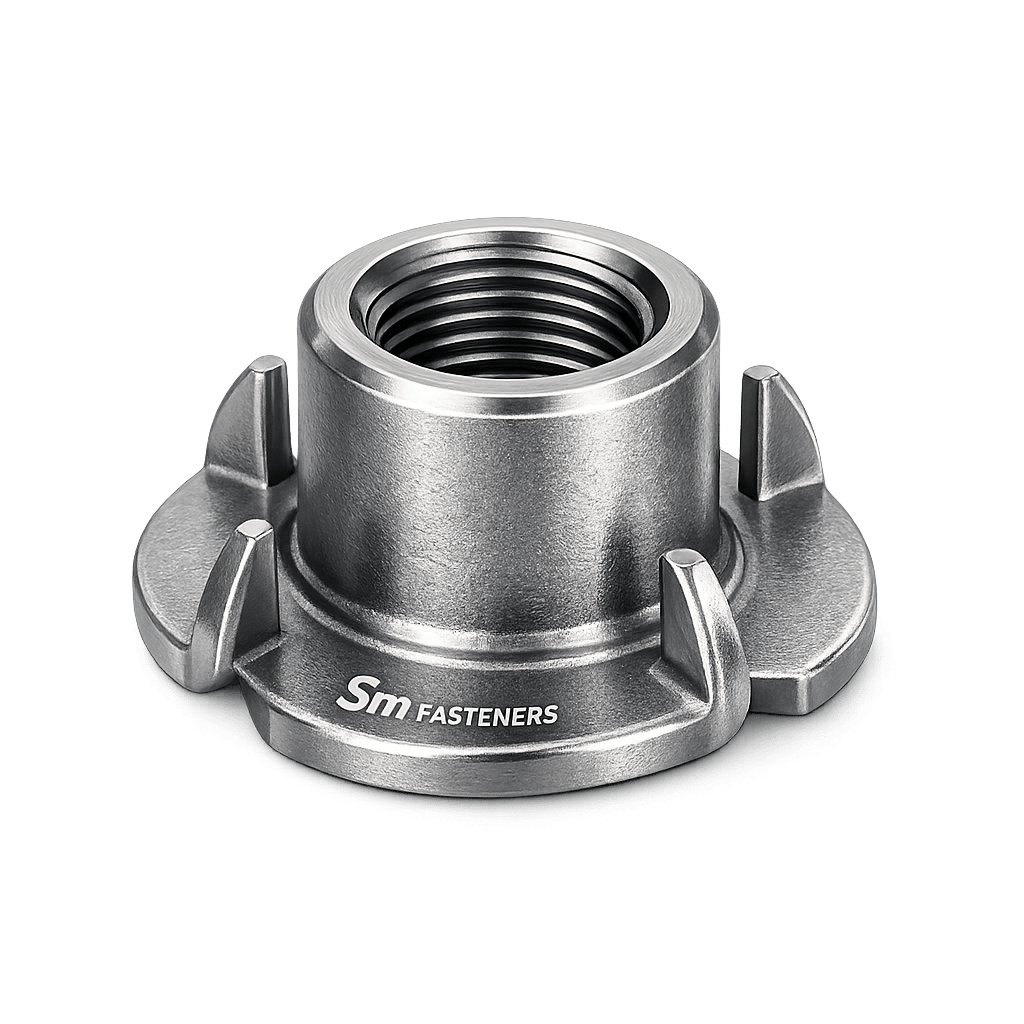
T-Nut Inserts are engineered fastening components designed to provide permanent internal threads in thin, soft, composite, or non-metallic substrates where direct tapping is impractical or structurally unreliable.
Across modern industrial assemblies, the transition toward:
- Lightweight structures
- Modular equipment design
- Composite materials
- High-cycle maintenance assemblies
has significantly increased reliance on insert-based fastening systems.
T-Nut Inserts are extensively specified in:
- Structural steel subassemblies
- Industrial machinery frames
- Panel mounting systems
- Equipment housings
- Railway interiors
- Offshore modular construction
- Heavy equipment fabrication
Unlike conventional nuts, T-Nut Inserts create a load-bearing threaded interface embedded into the parent material, transferring loads efficiently while preventing material pull-through.
SM Fasteners manufactures precision T-Nut Inserts under ISO 9001 quality systems, supporting global EPC and OEM procurement programs requiring dimensional reliability, traceability, and mechanical consistency.
2. Technical Definition
A T-Nut Insert is a flanged internally threaded fastener designed to be installed into a substrate (wood, metal sheet, composites, plastics, or engineered panels) to create a reusable threaded anchor.
Primary Functional Elements
| Component | Function |
|---|---|
| Internal Thread | Accepts mating bolt or screw |
| Flange (T-Head) | Distributes load over surface |
| Barrel / Body | Transfers load into substrate |
| Prongs / Serrations | Prevent rotation and pull-out |
| Seating Face | Ensures perpendicular alignment |
The geometry resembles the letter “T”, hence the designation.
3. Functional Role in Industrial Assemblies
T-Nut Inserts solve critical engineering challenges:
3.1 Thread Reinforcement
Soft materials cannot maintain thread integrity under repeated loading. Inserts create:
- Controlled thread tolerances
- Improved fatigue resistance
- Repeatable torque capability
3.2 Load Distribution
The flange increases effective bearing area:
Where:
- σ = bearing stress
- F = applied force
- A = flange contact area
Increasing flange diameter reduces localized crushing.
3.3 Replaceable Fastening Interface
Instead of replacing damaged panels or structures:
- Only the bolt is replaced.
- Parent material remains intact.
This is critical for maintenance-driven industries.
4. Load Mechanics & Force Behavior
T-Nut Inserts experience combined loading modes.
4.1 Axial Tensile Load
Bolt preload generates:
- Clamp force
- Pull-out load acting on insert
Where:
- D = insert diameter
- L = engagement length
- τ = shear strength of substrate
Pull-out resistance depends primarily on substrate properties.
4.2 Shear Load Transfer
Shear loads are resisted through:
- Barrel friction
- Prong engagement
- Flange bearing
Failure occurs when:
- substrate shears
- insert rotates
- flange embeds into material
4.3 Torque–Tension Relationship
Preload governs joint reliability.
Where:
- = preload
- = tightening torque
- = nut factor (0.15–0.25)
- = nominal diameter
Worked Example
For M8 bolt:
- Torque = 25 Nm
- K = 0.18
- D = 0.008 m
The insert must safely resist this load without pull-through.
5. Joint Design Principles
5.1 Thread Engagement Requirement
Minimum engagement:
| Material | Engagement Length |
|---|---|
| Steel | 1 × Diameter |
| Aluminum | 1.5 × Diameter |
| Plastics/Composites | 2–2.5 × Diameter |
5.2 Flange Diameter Selection
Recommended:
Ensures adequate bearing stress distribution.
5.3 Hole Preparation
Critical parameters:
- Perpendicular drilling
- Controlled tolerance
- Burr-free edges
- Correct pilot diameter
Incorrect hole sizing leads to:
- rotation failure
- misalignment
- loss of preload
5.4 Installation Methods
| Method | Application |
|---|---|
| Press-fit | Metal sheets |
| Hammer-in | Wood & panels |
| Hydraulic press | Production assemblies |
| Adhesive-assisted | Composite structures |
6. Preload Behaviour in Inserted Joints
Unlike standard nut/bolt joints, the system stiffness includes substrate deformation.
Joint stiffness model:
Where:
- = bolt stiffness
- = insert stiffness
- = substrate stiffness
Soft substrates dominate deformation behaviour.
7. Failure Mechanisms
7.1 Pull-Out Failure
Most common failure mode.
Occurs when:
- preload exceeds substrate shear capacity
- insufficient embedment depth
7.2 Insert Rotation
Caused by:
- improper prong penetration
- oversize hole
- vibration loosening
7.3 Fatigue Failure
Triggered by:
- cyclic loading
- fluctuating preload
- vibration environments
Common in railways and heavy equipment.
7.4 Thread Stripping
Occurs when:
- bolt grade exceeds insert strength
- insufficient thread engagement
7.5 Hydrogen Embrittlement
Risk exists in:
- electroplated high-strength steels (>1000 MPa)
SM Fasteners controls plating processes and baking cycles per ISO standards.
7.6 Stress Corrosion Cracking (SCC)
Critical in:
- chloride environments
- offshore installations
- chemical plants
Material selection becomes decisive.
8. Functional Selection Criteria
Engineers must evaluate:
| Parameter | Engineering Consideration |
|---|---|
| Substrate Type | Wood, metal, composite |
| Load Type | Static / dynamic |
| Installation Access | One-side or two-side |
| Environment | Corrosive, marine, chemical |
| Maintenance Frequency | Repeated assembly cycles |
| Temperature | Thermal expansion compatibility |
9. Role in Modern Engineering Systems
T-Nut Inserts enable:
- Modular assembly architecture
- Lightweight construction
- Serviceable equipment design
- Reduced welding requirements
- Faster field installation
They are increasingly specified by EPC contractors seeking predictable mechanical performance and installation repeatability.
SM Fasteners supports these requirements through:
- Precision cold forming & CNC machining
- Advanced alloy and corrosion-resistant materials
- Custom geometry development
- Global inspection and certification capability
10. Product Types and Engineering Variants
T-Nut Inserts are engineered in multiple configurations to satisfy different load transfer mechanisms, installation conditions, and substrate behaviors. Selection directly affects joint reliability, torque retention, and fatigue life.
SM Fasteners manufactures standardized and custom-engineered T-Nut Inserts aligned with global EPC specifications and OEM drawings.
10.1 Standard Pronged T-Nut Insert
Design Characteristics
- Flat flange head
- Cylindrical threaded barrel
- 3 or 4 anti-rotation prongs
Engineering Function
Prongs embed into substrate preventing rotational movement during bolt tightening.
Typical Applications
- Structural panels
- Wooden industrial bases
- Equipment enclosures
- Machine guards
10.2 Heavy-Duty T-Nut Insert
Designed for higher clamp loads.
Features:
- Increased flange thickness
- Extended barrel length
- Reinforced prongs or knurls
Used where:
- Dynamic loading exists
- High preload torque required
- Repeated maintenance cycles occur
10.3 Screw-In / Threaded Body T-Nut
Instead of prongs, the external body contains threads.
Advantages:
- High pull-out resistance
- Suitable for composites and plastics
- Controlled installation torque
Industries:
- Rail interiors
- Aerospace secondary structures
- Composite equipment panels
10.4 Weldable T-Nut Insert
Designed for permanent metallic installations.
Characteristics:
- Weld projection face
- No prongs
- Heat-resistant materials
Used in:
- Steel fabrications
- Heavy machinery frames
- Structural assemblies
10.5 Blind Installation T-Nut
Allows installation from one side only.
Applications:
- Closed structures
- Tubular frames
- Pre-assembled housings
10.6 PEEK T-Nut Inserts (High-Performance Polymer)
SM Fasteners manufactures PEEK-based T-Nut Inserts for advanced industrial environments.
Key Properties:
- Continuous service temperature: 260°C
- Electrical insulation
- Chemical resistance
- Lightweight assemblies
Industries:
- Semiconductor manufacturing
- LNG instrumentation
- Electrical isolation assemblies
- Chemical processing equipment
10.7 Custom Engineered T-Nut Inserts
Available from SM Fasteners:
- Non-standard flange diameters
- Metric/Unified hybrid threads
- Special coatings
- NACE-compliant materials
- Automation-ready installation designs
11. Dimensional Logic and Geometry
T-Nut performance depends heavily on geometry.
11.1 Critical Design Dimensions
| Symbol | Parameter | Engineering Role |
|---|---|---|
| D | Thread Diameter | Load capacity |
| P | Thread Pitch | Assembly precision |
| L | Barrel Length | Pull-out resistance |
| Df | Flange Diameter | Bearing stress distribution |
| Tf | Flange Thickness | Structural rigidity |
| Hp | Prong Height | Anti-rotation capability |
11.2 Standard Dimensional Specification Table (Metric Series)
| Thread Size | Pitch (mm) | Barrel Length (mm) | Flange Ø (mm) | Flange Thickness (mm) | Hole Size (mm) |
|---|---|---|---|---|---|
| M4 | 0.7 | 6–8 | 10 | 1.2 | 5 |
| M5 | 0.8 | 7–10 | 12 | 1.5 | 6 |
| M6 | 1.0 | 8–12 | 14 | 1.5 | 7 |
| M8 | 1.25 | 10–14 | 18 | 2.0 | 9 |
| M10 | 1.5 | 12–16 | 22 | 2.5 | 11 |
| M12 | 1.75 | 14–20 | 26 | 3.0 | 13 |
| M16 | 2.0 | 18–24 | 34 | 4.0 | 17 |
(Values represent industrial reference geometry aligned with SM Fasteners manufacturing capability.)
11.3 Geometric Design Principles
Flange Diameter Rule
Ensures proper bearing stress distribution.
Barrel Engagement Rule
Improves resistance against pull-out failure.
Prong Penetration Requirement
Prong height must exceed surface hardness penetration depth of substrate.
11.4 Weight Chart (SM Fasteners Reference)
| Size | Weight / Piece (g) | Weight / 100 pcs (kg) |
|---|---|---|
| M4 | 1.5 | 0.15 |
| M5 | 2.3 | 0.23 |
| M6 | 3.8 | 0.38 |
| M8 | 7.5 | 0.75 |
| M10 | 12.5 | 1.25 |
| M12 | 20.0 | 2.00 |
| M16 | 42.0 | 4.20 |
Aligned with SM Fasteners production mass tolerances.
12. Thread Standards and Tolerances
T-Nut Inserts must match bolt standards used globally in EPC projects.
12.1 Supported Thread Systems
| Thread System | Standard | Application Region |
|---|---|---|
| Metric Coarse | ISO 261 / ISO 965 | Global |
| Metric Fine | ISO 724 | Precision equipment |
| UNC | ASME B1.1 | USA |
| UNF | ASME B1.1 | Aerospace/High vibration |
| BSW | BS 84 | Legacy UK equipment |
| BSF | BS 84 | Retrofit projects |
12.2 Thread Tolerance Classes
| Thread | Internal Class | Typical Use |
|---|---|---|
| Metric | 6H | Standard industrial |
| Metric Precision | 5H | High accuracy |
| UNC/UNF | 2B | General engineering |
| Precision Unified | 3B | Aerospace assemblies |
SM Fasteners verifies threads using:
- GO / NO-GO gauges
- Optical thread inspection
- SPC-controlled production
13. Applicable International Standards
Although no single universal standard governs T-Nut Inserts, manufacturing aligns with multiple global specifications.
13.1 ISO Standards
| Standard | Scope |
|---|---|
| ISO 9001 | Quality Management System |
| ISO 898-1 | Mechanical properties of fasteners |
| ISO 965 | Thread tolerances |
| ISO 3506 | Stainless fasteners |
| ISO 3269 | Acceptance inspection |
13.2 DIN Standards Reference
| DIN Standard | Relevance |
|---|---|
| DIN 1624 | T-Nuts for woodworking |
| DIN 1626 | Insert fastening systems |
| DIN EN ISO 4032 | Hex nut references |
| DIN EN ISO 4759 | Dimensional tolerances |
13.3 ASTM Standards
| ASTM Standard | Application |
|---|---|
| ASTM A563 | Carbon steel nuts |
| ASTM A194 | Alloy steel & stainless nuts |
| ASTM F568 | Metric mechanical properties |
| ASTM B633 | Zinc coating |
13.4 British Standards (BS)
| BS Standard | Application |
|---|---|
| BS 3692 | Metric fasteners |
| BS EN 10204 | Certification |
| BS 4320 | Washer interface compatibility |
14. Property Class Compatibility
Insert strength must match bolt strength.
| Bolt Grade | Compatible Insert Material |
|---|---|
| 4.6 | Low carbon steel |
| 8.8 | Medium carbon steel |
| 10.9 | Alloy steel insert |
| A2-70 | Stainless steel insert |
| A4-80 | Marine-grade stainless |
Incorrect pairing leads to:
- thread stripping
- preload loss
- fatigue cracking
15. Interchangeability Considerations
Global projects demand interchangeability.
Critical parameters:
- Thread pitch compatibility
- Bolt seating face alignment
- Flange clearance
- Hole tolerance
SM Fasteners designs inserts suitable for multi-standard environments, allowing use with ISO, ASTM, and BS hardware without redesign.
16. Dimensional Tolerance Control
Typical production tolerances:
| Feature | Tolerance |
|---|---|
| Thread pitch diameter | ±0.02 mm |
| Flange diameter | ±0.05 mm |
| Barrel length | ±0.10 mm |
| Concentricity | ≤0.05 mm |
| Perpendicularity | ≤0.03 mm |
These controls ensure repeatable preload performance.
17. Engineering Design Integration
When integrated correctly, T-Nut Inserts provide:
- Controlled clamping force
- Reduced substrate damage
- Improved fatigue resistance
- Rapid assembly and disassembly capability
SM Fasteners supports EPC and OEM engineering teams through:
- Custom dimensional engineering
- CAD validation support
- Prototype manufacturing
- Application-based geometry optimization
18. Material Grades and Engineering Selection Criteria
Material selection for T-Nut Inserts directly determines:
- Load carrying capacity
- Thread durability
- Corrosion resistance
- Temperature performance
- Long-term reliability under cyclic service
Unlike conventional nuts, T-Nut Inserts operate within mixed-material interfaces, meaning galvanic compatibility and substrate interaction must also be considered.
SM Fasteners manufactures T-Nut Inserts using a full industrial material portfolio aligned with EPC specifications and international standards.
18.1 Industrial Material Range
| Material Category | Typical Grades | Standards Reference |
|---|---|---|
| Carbon Steel | C15, C20, C35, EN8 | ASTM A563 / ISO 898 |
| Alloy Steel | 4140, 4340, 42CrMo4 | ASTM A194 / ISO 898 |
| Stainless Steel | A2-70, A4-80 | ISO 3506 |
| Duplex Stainless | UNS S31803 | ASTM A182 |
| Super Duplex | UNS S32750 | NORSOK / ISO 15156 |
| Nickel Alloys | Inconel 625, 718 | ASTM B446 |
| Incoloy | 825, 800HT | ASTM B408 |
| Monel | 400, K500 | ASTM B164 |
| Hastelloy | C276 | ASTM B574 |
| SMO 254 | UNS S31254 | ASTM A182 |
| Engineering Polymer | PEEK | ASTM D6262 |
18.2 Material Selection Logic
Engineering evaluation considers multiple interacting variables.
| Design Parameter | Selection Impact |
|---|---|
| Substrate hardness | Prevent embedment failure |
| Bolt strength | Avoid thread stripping |
| Environment | Corrosion compatibility |
| Temperature | Mechanical retention |
| Maintenance cycles | Wear resistance |
| Weight reduction | Polymer or duplex materials |
18.3 Mechanical Property Comparison Table
| Material | Yield Strength (MPa) | UTS (MPa) | Temp Limit °C | Corrosion Resistance | Relative Cost | Typical Applications |
|---|---|---|---|---|---|---|
| Carbon Steel | 250–400 | 400–600 | 300 | Moderate | Low | Structural assemblies |
| Alloy Steel | 700–1000 | 900–1200 | 450 | Moderate | Medium | Heavy machinery |
| SS A2-70 | 450 | 700 | 400 | High | Medium | General industrial |
| SS A4-80 | 600 | 800 | 450 | Very High | Medium-High | Marine/offshore |
| Duplex | 550 | 800 | 300 | Excellent | High | Oil & Gas |
| Super Duplex | 650 | 900 | 300 | Extreme | Very High | Offshore platforms |
| Inconel 625 | 450 | 850 | 1000 | Outstanding | Premium | High temperature |
| Monel 400 | 240 | 550 | 480 | Seawater resistant | High | Marine |
| SMO 254 | 300 | 650 | 350 | Acid resistant | High | Chemical plants |
| PEEK | — | — | 260 | Chemical inert | High | Electrical isolation |
19. Corrosion Resistance vs Environment
Correct alloy selection prevents premature failure.
| Environment | Recommended Material | Reason |
|---|---|---|
| Outdoor Construction | Zinc plated steel | Economical protection |
| Marine Atmosphere | A4-80 / Duplex | Chloride resistance |
| Seawater Immersion | Super Duplex / Monel | Pitting resistance |
| Acidic Chemical Plant | Hastelloy C276 | Chemical stability |
| LNG Cryogenic | Austenitic Stainless | Toughness retention |
| H₂S Sour Service | NACE compliant Duplex | Sulfide stress resistance |
| High Temperature Furnace | Inconel | Oxidation resistance |
| Electrical Isolation | PEEK | Non-conductive |
SM Fasteners supports NACE MR0175 / ISO 15156 compliant material supply for sour service projects.
20. Mechanical Properties by Fastener Property Class
| Property Class | Yield Strength (MPa) | Tensile Strength (MPa) | Typical Insert Material |
|---|---|---|---|
| 4 | 225 | 400 | Mild steel |
| 5 | 300 | 500 | Medium carbon |
| 8 | 640 | 800 | Heat-treated steel |
| 10 | 900 | 1000 | Alloy steel |
| 12 | 1080 | 1200 | Quenched alloy steel |
| A2-70 | 450 | 700 | SS 304 |
| A4-80 | 600 | 800 | SS 316 |
Insert material must never be weaker than mating bolt threads.
21. Heat Treatment Processes
Heat treatment optimizes:
- hardness
- fatigue resistance
- wear performance
- preload retention
21.1 Carbon Steel Heat Treatment
Process Flow
- Austenitizing
- Quenching (oil/polymer)
- Tempering
Result:
- Increased tensile strength
- Improved thread wear resistance
Typical hardness: 22–32 HRC
21.2 Alloy Steel Hardening
Applied for high-load T-Nut Inserts.
Produces:
- Property class 10/12 capability
- High torque resistance
- Improved fatigue life
21.3 Stainless Steel Processing
Austenitic grades are not hardened by quenching.
Instead:
- Solution annealing
- Stress relieving
- Cold working for strength enhancement
21.4 Sour Service Hardness Control
Per NACE MR0175:
| Material | Max Hardness |
|---|---|
| Carbon steel | 22 HRC |
| Duplex | 28 HRC |
| Nickel alloys | Controlled by spec |
SM Fasteners maintains furnace traceability and calibrated hardness verification.
21.5 Heat Treatment Verification
Performed through:
- Rockwell hardness testing
- Microstructure examination
- Grain refinement inspection
- Heat lot traceability
22. End-to-End Manufacturing Workflow
SM Fasteners follows controlled manufacturing aligned with ISO 9001 certified processes.
22.1 Raw Material Verification
Incoming inspection includes:
- Mill Test Certificate verification
- Chemical composition check
- PMI testing
- Heat number assignment
22.2 Forging vs Machining
| Method | Advantage | Use Case |
|---|---|---|
| Cold Forging | Grain flow strength | High-volume inserts |
| Hot Forging | Large sizes | Heavy-duty inserts |
| CNC Machining | Precision/custom | Special alloys |
| Polymer Injection | PEEK inserts | Electrical applications |
Forged inserts exhibit superior fatigue performance due to directional grain structure.
22.3 Flange Forming
Processes include:
- Progressive die forming
- Multi-station cold headers
- CNC facing for precision flanges
22.4 Prong / Anti-Rotation Feature Formation
Methods:
- Coining
- Punch forming
- Serration rolling
These features prevent insert rotation during tightening.
22.5 Thread Manufacturing
Thread Rolling (Preferred)
Advantages:
- Increased fatigue life
- Work hardening
- Superior surface finish
Thread Cutting
Used for:
- Exotic alloys
- Low-volume customization
22.6 Deburring and Surface Preparation
Critical for:
- Coating adhesion
- Installation safety
- Dimensional accuracy
Processes:
- Vibratory finishing
- Shot blasting
- Chemical cleaning
23. Surface Finishing & Coating Technologies
Surface engineering directly influences service life.
23.1 Coating Comparison Table
| Coating | Thickness | Corrosion Resistance | Temperature Limit | Typical Use |
|---|---|---|---|---|
| Zinc Electroplated | 5–12 µm | Moderate | 120°C | Indoor |
| HDG | 45–85 µm | High | 200°C | Structural |
| Zinc Flake | 8–12 µm | Very High | 300°C | Automotive |
| Phosphate | 2–5 µm | Low | 250°C | Pre-lubrication |
| Black Oxide | <2 µm | Minimal | 300°C | Machinery |
| Nickel Plating | 10–25 µm | High | 400°C | Chemical |
| PTFE Coated | Variable | Excellent | 260°C | Anti-galling |
| Passivation | — | Stainless enhancement | — | SS inserts |
23.2 Hydrogen Embrittlement Control
High-strength plated inserts undergo:
- Post-plating baking
- Controlled electroplating chemistry
- ISO process validation
23.3 Friction Control Coatings
Used to stabilize torque–tension relationship.
Typical nut factor ranges:
| Surface Condition | Nut Factor K |
|---|---|
| Dry steel | 0.20–0.25 |
| Zinc plated | 0.18 |
| Lubricated | 0.15 |
| PTFE coated | 0.10–0.13 |
23.4 Surface Preparation for PEEK Inserts
PEEK manufacturing involves:
- Precision molding
- Annealing cycles
- Dimensional stabilization
Ensures creep resistance under preload.
24. Manufacturing Traceability System
Each production lot at SM Fasteners includes:
- Heat number tracking
- Process routing cards
- Operator identification
- Inspection records
- Batch serialization
This enables complete lifecycle traceability required by EPC and oil & gas projects.
25. Engineering Advantages of SM Fasteners Manufacturing Capability
- ISO 9001 certified production system
- MSME & UKAF accredited operations
- Advanced alloy machining capability
- PEEK fastener manufacturing integration
- Custom engineering for global OEM requirements
- Controlled coating and heat treatment partnerships
T-Nut Inserts supplied by SM Fasteners are engineered not only as fastening components but as load-bearing mechanical interfaces designed for long-term industrial service reliability.
26. Inspection and Quality Control Framework
T-Nut Inserts function as load-critical threaded anchors, therefore inspection requirements extend beyond dimensional verification.
SM Fasteners operates under an ISO 9001 certified Quality Management System, ensuring every production batch complies with international industrial procurement standards.
Quality assurance integrates:
- Raw material validation
- In-process inspection
- Mechanical verification
- Surface treatment validation
- Final release certification
26.1 Incoming Material Inspection
All materials undergo verification prior to manufacturing.
| Inspection Activity | Method | Purpose |
|---|---|---|
| MTC Review | EN 10204 3.1 | Chemical & mechanical compliance |
| PMI Testing | XRF Analyzer | Alloy confirmation |
| Visual Inspection | ISO 3269 | Surface defects |
| Hardness Check | Rockwell | Heat condition verification |
| Heat Number Allocation | Traceability control | Lifecycle tracking |
26.2 Dimensional Inspection
Critical dimensions affecting performance:
- Internal thread accuracy
- Flange diameter
- Barrel length
- Perpendicularity
- Concentricity
Inspection Tools:
- Digital height gauges
- Profile projectors
- Thread plug gauges (GO / NO-GO)
- CMM inspection for critical projects
26.3 Mechanical Testing
| Test | Standard | Objective |
|---|---|---|
| Proof Load Test | ISO 898 | Load verification |
| Tensile Test | ASTM F606 | Material strength |
| Torque Test | Internal procedure | Thread durability |
| Pull-Out Test | Application simulation | Insert retention |
| Hardness Testing | ISO 6508 | Heat treatment validation |
26.4 Non-Destructive Testing (NDT)
Applied when required by EPC specifications.
| NDT Method | Application |
|---|---|
| Magnetic Particle Testing | Surface crack detection |
| Dye Penetrant Testing | Stainless components |
| Ultrasonic Inspection | Heavy forged inserts |
| Visual Weld Inspection | Weldable T-Nuts |
26.5 Coating Inspection
| Test | Requirement |
|---|---|
| Coating Thickness | Magnetic gauge |
| Adhesion Test | Cross hatch |
| Salt Spray Test | ASTM B117 |
| Passivation Verification | ASTM A967 |
26.6 Certification & Documentation
SM Fasteners supplies complete documentation packages:
- EN 10204 3.1 Material Test Certificate
- Heat Treatment Reports
- Dimensional Inspection Reports
- Coating Compliance Reports
- Certificate of Conformity (CoC)
- Third-Party Inspection (TPI) — upon request
27. Industry Applications
T-Nut Inserts provide engineered threaded anchoring solutions across multiple heavy industries.
27.1 Construction & Structural Steel
Used for:
- Curtain wall mounting
- Structural panels
- Modular building assemblies
- Equipment bases
Benefits:
- Eliminates field tapping
- Rapid installation
- Serviceable connections
27.2 Oil & Gas Industry
Upstream
- Skid-mounted equipment
- Drilling cabins
- Instrument panels
Midstream
- Compressor housing assemblies
- Pipe support structures
Downstream
- Refinery access platforms
- Maintenance panels
Materials often specified:
- Duplex
- Super Duplex
- A4-80 stainless
- NACE compliant alloys
27.3 Power Generation
Applications include:
- Turbine enclosures
- Control cabinets
- Generator housings
- Solar mounting systems
Requirements:
- vibration resistance
- repeatable maintenance access
27.4 Petrochemical & Chemical Processing
Chemical resistance critical.
Typical selections:
- SMO 254
- Hastelloy C276
- PTFE coated inserts
Used for:
- reactor insulation panels
- piping supports
- access covers
27.5 LNG & Offshore Platforms
Challenges:
- Chloride exposure
- cyclic vibration
- thermal expansion
Recommended materials:
- Super Duplex
- Monel
- Inconel
27.6 Automotive & Heavy Equipment
Used in:
- chassis subassemblies
- equipment cabins
- machinery guards
- removable covers
Advantages:
- automation compatibility
- reduced assembly time
27.7 Railways & Infrastructure
Applications:
- coach interiors
- flooring systems
- electrical cabinets
- signaling infrastructure
PEEK inserts are often selected for electrical insulation.
27.8 Shipbuilding & Marine Engineering
Typical uses:
- deck equipment mounting
- composite panels
- interior structural components
Primary requirement: corrosion resistance.
28. Failure Prevention and Reliability Engineering
Common failure prevention practices:
| Failure Mode | Engineering Control |
|---|---|
| Pull-out | Correct embedment depth |
| Rotation | Serrated/pronged design |
| Thread stripping | Grade matching |
| Fatigue | Controlled preload |
| SCC | Proper alloy selection |
| Hydrogen embrittlement | Controlled plating & baking |
29. Tightening Torque Chart
(Reference values — dry condition unless specified)
| Size | Grade 8.8 (Nm) | Grade 10.9 (Nm) | Stainless A2-70 (Nm) |
|---|---|---|---|
| M4 | 3 | 4 | 2.5 |
| M5 | 6 | 8 | 5 |
| M6 | 10 | 14 | 9 |
| M8 | 25 | 35 | 22 |
| M10 | 49 | 70 | 45 |
| M12 | 85 | 120 | 75 |
| M16 | 210 | 295 | 180 |
Lubrication reduces torque by ~15–25%.
30. Proof Load & Tensile Strength Table
| Size | Property Class | Proof Load (kN) | Tensile Strength (kN) |
|---|---|---|---|
| M6 | 8 | 8.8 | 10.5 |
| M8 | 8 | 16 | 20 |
| M10 | 8 | 25 | 31 |
| M12 | 8 | 36 | 45 |
| M16 | 8 | 64 | 80 |
| M12 | 10 | 51 | 64 |
| M16 | 10 | 90 | 110 |
31. Preload Calculation — Engineering Method
Formula
Fp=K×DT
Where:
- Fp = Preload (N)
- T = Torque (Nm)
- K = Nut Factor
- D = Nominal Diameter (m)
Worked Example — M10 Insert
Torque applied = 50 Nm
K = 0.18
Diameter = 0.01 m
Insert pull-out capacity must exceed this value with safety factor ≥ 2.
32. Thread Standards & Tolerance Table
| System | Standard | Internal Class |
|---|---|---|
| Metric | ISO 261 / ISO 965 | 6H |
| UNC | ASME B1.1 | 2B |
| UNF | ASME B1.1 | 2B |
| BSW | BS 84 | Medium |
| BSF | BS 84 | Medium |
33. Surface Finish Performance Comparison
| Finish | Corrosion Resistance | Friction Control | Galling Resistance | Service Environment |
|---|---|---|---|---|
| Zinc Plated | Medium | Good | Moderate | Indoor |
| HDG | High | Moderate | Good | Structural outdoor |
| Zinc Flake | Very High | Stable | Excellent | Automotive |
| Nickel | High | Good | Good | Chemical |
| PTFE | Excellent | Excellent | Excellent | Offshore |
| Passivated SS | Excellent | Stable | Good | Marine |
34. T-Nut Insert Weight Reference Chart
(Aligned with SM Fasteners manufacturing data)
| Size | Weight / Piece (g) | Weight / 100 pcs (kg) |
|---|---|---|
| M4 | 1.5 | 0.15 |
| M5 | 2.3 | 0.23 |
| M6 | 3.8 | 0.38 |
| M8 | 7.5 | 0.75 |
| M10 | 12.5 | 1.25 |
| M12 | 20.0 | 2.00 |
| M16 | 42.0 | 4.20 |
Used for logistics planning and freight estimation.
35. Export Capability & Global Supply Readiness
SM Fasteners supports international project procurement through structured export processes.
35.1 Industrial Packaging
- VCI corrosion protection
- Thread protection caps
- Batch identification labels
- Moisture barrier packaging
- Barcode traceability
35.2 Export Crating
- ISPM-15 compliant wooden crates
- Vacuum sealing for offshore shipments
- Shock-resistant palletization
- Container optimization planning
35.3 Documentation Package
Provided with shipments:
- Material Test Certificates (EN 10204 3.1 / 3.2)
- Heat Treatment Reports
- Inspection & Dimensional Reports
- Coating Certificates
- Certificate of Conformity
- Packing List & Traceability Records
36. Integration with SM Fasteners Engineering Capability
SM Fasteners delivers T-Nut Inserts aligned with global industrial expectations:
- ISO 9001 certified manufacturing system
- MSME & UKAF recognized quality framework
- Advanced alloy machining capability
- PEEK fastener manufacturing expertise
- Custom engineered insert geometry
- EPC project supply readiness
Capabilities include:
- Custom thread systems
- Special corrosion-resistant alloys
- High-temperature fasteners
- Prototype development
- Global logistics coordination
37. Engineering Summary
T-Nut Inserts represent a critical fastening solution where:
- Direct threading is impractical
- Load distribution must be controlled
- Repeat maintenance is required
- Mixed-material assemblies exist
Proper engineering integration requires coordinated consideration of:
- preload mechanics
- substrate interaction
- corrosion environment
- material compatibility
- manufacturing quality control
Through certified processes, advanced material capability, and comprehensive inspection systems, SM Fasteners supplies T-Nut Inserts engineered for long-term performance across construction, oil & gas, power, petrochemical, marine, infrastructure, and heavy engineering sectors worldwide.