

Tap-End Stud Bolt
1. Industry Context
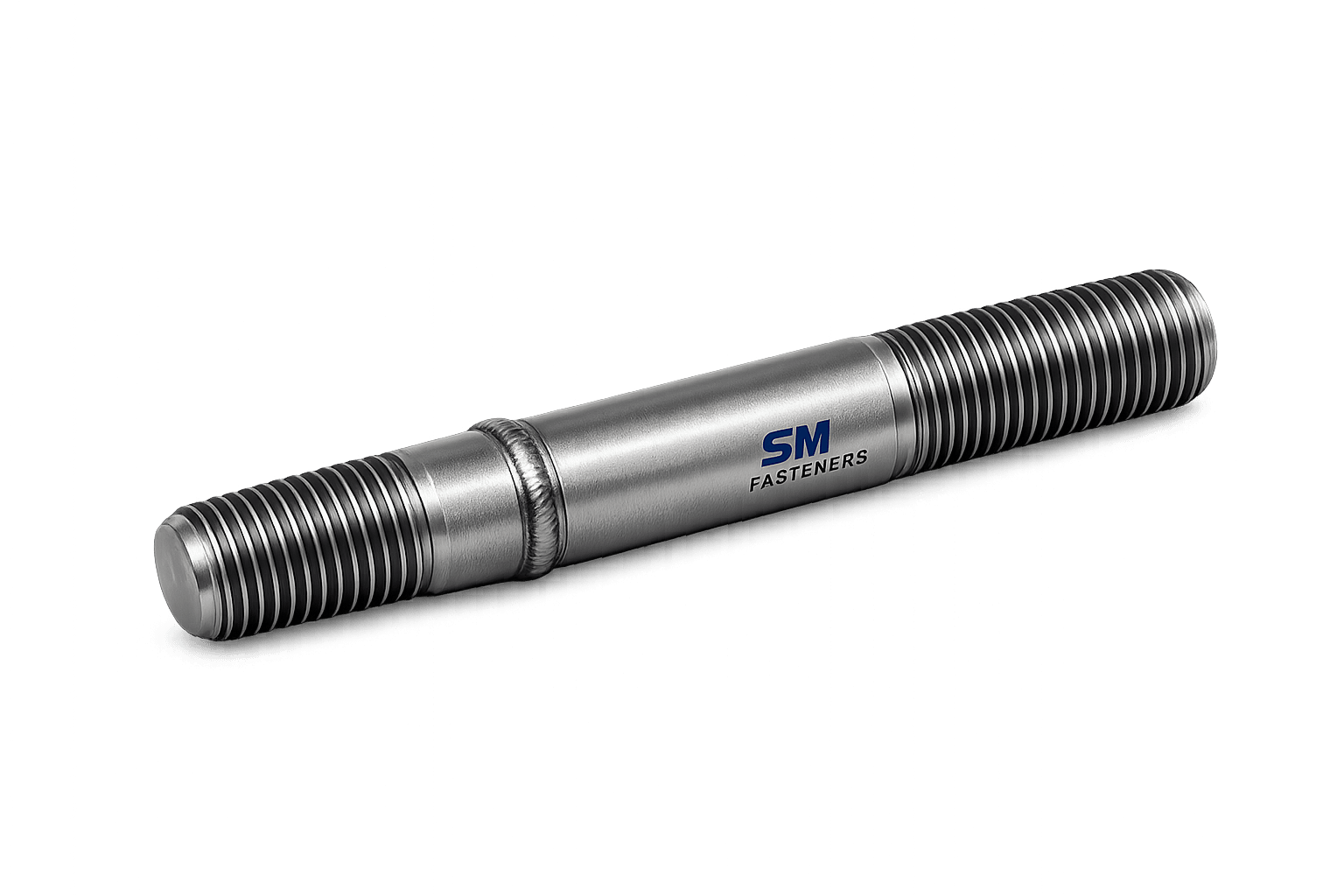
Tap-End Stud Bolts are specialized engineered fasteners extensively used in permanent or semi-permanent threaded assemblies where one end is installed directly into a tapped component while the opposite end receives a nut.
They are critical fastening solutions across industries requiring:
- High vibration resistance
- Accurate preload control
- Repetitive assembly/disassembly capability
- Reduced thread wear in parent equipment
- Reliable load transfer under cyclic loading
Typical Industrial Deployment
| Industry Sector | Functional Requirement |
|---|---|
| Oil & Gas | Valve bodies, pump housings, pressure equipment |
| Power Generation | Turbine casings, heat exchangers |
| Petrochemical | Flanged connections, reactors |
| Construction | Structural steel interfaces |
| Heavy Equipment | Engine blocks, gearbox assemblies |
| Offshore & Marine | Corrosion-resistant threaded joints |
| Rail & Infrastructure | Permanent mounting interfaces |
In EPC projects, Tap-End Stud Bolts are preferred when equipment integrity must exceed lifecycle maintenance intervals.
SM Fasteners manufactures tap-end stud bolts aligned with global project specifications, ensuring compatibility with ISO, ASTM, DIN, and BS systems.
2. Technical Definition
A Tap-End Stud Bolt is a double-ended threaded fastener consisting of:
- Tap End (Short Threaded Portion)
Installed permanently into a tapped hole. - Nut End (Long Threaded Portion)
Used for clamping with nut and washer. - Unthreaded Body or Reduced Shank (optional)
Engineering Definition
A tap-end stud bolt transfers axial load through tensile preload while minimizing wear on parent material threads.
Unlike standard bolts:
- No head exists.
- Load path is purely axial.
- Clamping force is controlled via nut tightening.
3. Functional Role in Mechanical Assemblies
Primary Functions
- Establish reliable clamping force.
- Protect base material threads.
- Enable repeated maintenance cycles.
- Improve fatigue life of joints.
- Maintain alignment accuracy.
Advantages Over Conventional Bolts
| Parameter | Tap-End Stud Bolt | Hex Bolt |
|---|---|---|
| Thread wear | Minimal | High |
| Alignment | Excellent | Moderate |
| Fatigue resistance | Superior | Lower |
| Maintenance cycles | High | Limited |
| Preload repeatability | High | Variable |
4. Load Mechanics & Force Behavior
Tap-end studs behave as elastic tension members.
Fundamental Load Path
Torque → Bolt Tension → Clamping Force → Joint CompressionThe joint integrity depends on maintaining preload greater than operational separating forces.
4.1 Bolt Preload Concept
Preload is the intentional tensile stress induced during tightening.
Where:
- = Preload force (N)
- = Applied torque (Nm)
- = Nut factor
- = Nominal diameter (m)
Worked Example
Given
- Size: M20
- Torque: 420 Nm
- Nut factor: 0.18
This preload ensures proper sealing and fatigue resistance.
4.2 Force Distribution in Stud Joints
Tap-end studs create:
- Uniform compression
- Reduced bending stress
- Improved fatigue resistance
Load sharing:
| Component | Load Behavior |
|---|---|
| Stud | Elastic tension |
| Joint | Compression |
| Threads | Shear + friction |
5. Thread Engagement Principles
Correct engagement depth prevents thread stripping.
Recommended Engagement
| Material | Engagement Length |
|---|---|
| Steel | 1 × Diameter |
| Cast Iron | 1.5 × Diameter |
| Aluminum | 2 × Diameter |
| Stainless Steel | 1.25 × Diameter |
SM Fasteners designs tap-end threads per application metallurgy.
6. Joint Design Principles
6.1 Tap-End Installation Concept
The tap-end acts as a semi-permanent anchor.
Installation methods:
- Double-nut method
- Stud driver installation
- Hydraulic insertion
Tap-end typically tightened to lower torque than nut end.
6.2 Elastic Interaction of Joint
Joint stiffness ratio:
Where:
- = Bolt stiffness
- = Joint stiffness
Higher joint stiffness reduces fatigue risk.
6.3 Torque–Tension Relationship
Only 10–15% of torque generates preload.
| Energy Loss | Percentage |
|---|---|
| Thread friction | 40% |
| Bearing friction | 45% |
| Useful preload | 15% |
Hence surface finish and lubrication are critical.
7. Mechanical Behavior Under Service Loads
Tensile Loading
Primary operational mode.
Shear Loading
Transferred through friction between clamped parts.
Bending
Minimized due to headless design.
Fatigue Resistance
Superior due to consistent preload.
8. Failure Mechanisms
8.1 Fatigue Failure
Caused by fluctuating load exceeding endurance limit.
Mitigation:
- Correct preload
- Rolled threads
- Surface treatment
8.2 Thread Stripping
Occurs if engagement insufficient.
8.3 Hydrogen Embrittlement
High-strength grades require controlled plating processes.
SM Fasteners applies controlled baking cycles after electroplating.
8.4 Stress Corrosion Cracking (SCC)
Occurs in:
- Chlorides
- H₂S environments
- High temperature conditions
NACE MR0175 compliant materials available.
8.5 Galling (Stainless Steel)
Prevented using:
- Lubrication
- Silver plating
- MoS₂ coatings
9. Functional Selection Criteria
Engineers must evaluate:
| Parameter | Selection Basis |
|---|---|
| Load | Tensile capacity |
| Temperature | Material grade |
| Corrosion | Alloy/coating |
| Maintenance | Stud design |
| Vibration | Preload level |
| Environment | NACE compliance |
10. Advantages in EPC Projects
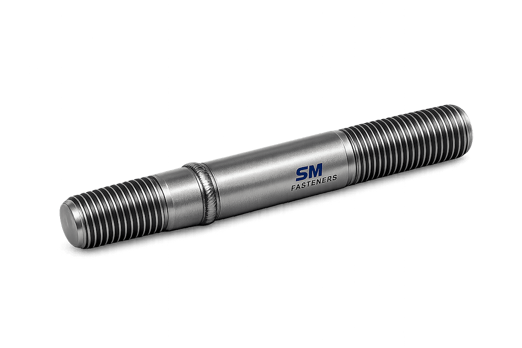
Tap-End Stud Bolts allow:
- Equipment alignment stability
- Predictable preload control
- Reduced downtime
- Simplified maintenance
- Long equipment lifecycle
SM Fasteners supports project-specific engineering including:
- Custom thread lengths
- Dual-standard threading
- Special alloy manufacturing
- PEEK high-temperature insulation fasteners
11. Product Types and Variants of Tap-End Stud Bolts
Tap-End Stud Bolts are engineered according to joint configuration, installation method, and service environment. Unlike fully threaded studs, geometry is intentionally asymmetric to optimize load transfer and installation reliability.
SM Fasteners manufactures tap-end studs customized to EPC specifications, ensuring interchangeability with international equipment standards.
11.1 Standard Tap-End Stud Configuration
Primary Elements
- Tap-End Thread (Short End)
- Plain or Reduced Shank (Optional)
- Nut-End Thread (Long End)
Short Thread (Tap End) | Body/Shank | Long Thread (Nut End)11.2 Common Industrial Variants
| Type | Description | Application |
|---|---|---|
| Standard Tap-End Stud | Short tap thread + long nut thread | Pumps, valves |
| Reduced Shank Stud | Shank dia < thread dia | Fatigue resistance |
| Continuous Thread Tap-End | Fully threaded | Limited space joints |
| Fine Thread Nut-End | Higher preload control | Pressure equipment |
| Double Standard Stud | Metric tap + UNC nut end | Imported machinery |
| Interference Fit Tap-End | Locking installation | High vibration equipment |
| Collar Stud | Positive positioning stop | Alignment assemblies |
| PEEK Tap-End Stud | Electrical isolation | LNG, electronics, chemical plants |
11.3 Functional Differences from Other Stud Types
| Stud Type | Tap-End | Double-End | Fully Threaded |
|---|---|---|---|
| Permanent installation | ✔ | ✖ | ✖ |
| Maintenance removal | Easy | Moderate | Difficult |
| Thread protection | High | Medium | Low |
| Alignment precision | Excellent | Good | Moderate |
12. Dimensional Logic and Geometry
Tap-end stud design is governed by load mechanics and thread engagement behavior.
12.1 Basic Dimensional Parameters
| Symbol | Description |
|---|---|
| d | Nominal diameter |
| P | Thread pitch |
| L | Overall length |
| b1 | Tap-end thread length |
| b2 | Nut-end thread length |
| ds | Shank diameter |
| Le | Engagement length |
12.2 Recommended Thread Length Ratios
| Diameter Range | Tap-End Length | Nut-End Length |
|---|---|---|
| M6–M12 | 1d | 2d |
| M16–M24 | 1–1.25d | 2–2.5d |
| M27–M48 | 1.25d | 2.5–3d |
| M52+ | Project-specific | Project-specific |
Tap-end threads are intentionally shorter to prevent over-stressing parent material.
13. Dimensional Specification Table (Metric Series)
Standard Tap-End Stud Dimensions
| Size | Pitch (mm) | Tap-End Length (mm) | Nut-End Length (mm) | Standard Length Range (mm) |
|---|---|---|---|---|
| M8 | 1.25 | 8 | 16 | 30–120 |
| M10 | 1.5 | 10 | 20 | 40–150 |
| M12 | 1.75 | 12 | 24 | 50–200 |
| M16 | 2.0 | 16 | 32 | 60–300 |
| M20 | 2.5 | 20 | 40 | 70–400 |
| M24 | 3.0 | 24 | 48 | 80–500 |
| M30 | 3.5 | 30 | 60 | 100–600 |
| M36 | 4.0 | 36 | 72 | 120–700 |
| M42 | 4.5 | 42 | 84 | 140–800 |
| M48 | 5.0 | 48 | 96 | 160–1000 |
Custom dimensions manufactured by SM Fasteners per drawing or EPC datasheet.
14. Thread Forms and Geometry
Thread geometry directly affects:
- Load distribution
- Fatigue life
- Assembly torque
- Galling tendency
14.1 International Thread Systems
| Standard | Thread Form | Region/Application |
|---|---|---|
| ISO Metric | 60° | Global |
| UNC | Coarse Unified | USA equipment |
| UNF | Fine Unified | High preload |
| BSW | Whitworth | Legacy UK |
| BSF | Fine Whitworth | Rail & marine |
| NPT | Tapered | Pressure sealing |
| ACME | Power transmission | Special use |
14.2 Thread Tolerance Classes
| Thread | External | Internal |
|---|---|---|
| ISO Metric | 6g | 6H |
| Precision Assembly | 4g6g | 5H |
| Unified UNC/UNF | 2A | 2B |
| High Accuracy | 3A | 3B |
SM Fasteners ensures CNC-controlled threading aligned with ISO inspection systems.
15. Applicable Global Standards
Tap-End Stud Bolts typically combine multiple international standards.
15.1 ISO Standards
| Standard | Scope |
|---|---|
| ISO 898-1 | Mechanical properties |
| ISO 261 | Metric thread pitch |
| ISO 965 | Thread tolerance |
| ISO 3506 | Stainless fasteners |
| ISO 4759 | Tolerances |
| ISO 3269 | Acceptance inspection |
15.2 ASTM Standards
| Standard | Application |
|---|---|
| ASTM A193 | Alloy steel stud bolts |
| ASTM A320 | Low temperature service |
| ASTM A194 | Nuts for studs |
| ASTM F593 | Stainless studs |
| ASTM F568M | Metric mechanical properties |
15.3 DIN Standards
| DIN Standard | Description |
|---|---|
| DIN 939 | Tap-end studs |
| DIN 938 | Double-end studs |
| DIN 13 | Metric threads |
| DIN 267 | Fastener coatings |
DIN 939 forms the principal dimensional reference for tap-end studs.
15.4 British Standards
| BS Standard | Scope |
|---|---|
| BS 4439 | Stud bolts |
| BS 3643 | Thread system |
| BS EN ISO equivalents | Harmonized standards |
16. Property Class Systems
Mechanical strength classification follows ISO or ASTM systems.
Metric Property Classes
| Class | Yield Strength (MPa) | Tensile Strength (MPa) |
|---|---|---|
| 4.6 | 240 | 400 |
| 5.8 | 400 | 500 |
| 8.8 | 640 | 800 |
| 10.9 | 940 | 1040 |
| 12.9 | 1100 | 1220 |
ASTM Equivalent Grades
| ISO Class | ASTM Equivalent |
|---|---|
| 8.8 | A193 B7 |
| 10.9 | B16 |
| Stainless | A193 B8/B8M |
| Low Temp | A320 L7 |
SM Fasteners supplies cross-standard compliant fasteners for international projects.
17. Dimensional Tolerances
Critical tolerances include:
| Parameter | Typical Tolerance |
|---|---|
| Diameter | ISO h6 |
| Length | ±0.5 mm |
| Pitch error | ISO 965 |
| Straightness | 0.001 × length |
| Concentricity | ≤0.05 mm |
18. Interchangeability Considerations
Global projects frequently require compatibility between:
- Metric equipment
- American pressure vessels
- European machinery
SM Fasteners provides:
- Dual-thread studs
- Mixed-standard manufacturing
- Project-specific tolerance matching
19. Thread Engagement Stress Distribution
Stress is not uniform across threads.
Load sharing:
| Thread Position | Load Share |
|---|---|
| First thread | 35% |
| Second | 25% |
| Third | 15% |
| Remaining | 25% |
Correct geometry prevents first-thread overload.
20. Weight Chart — Tap-End Stud Bolts
(Aligned with SM Fasteners manufacturing data)
| Size | Weight per Piece (kg) | Weight per 100 pcs (kg) |
|---|---|---|
| M10 × 80 | 0.05 | 5 |
| M12 × 100 | 0.09 | 9 |
| M16 × 120 | 0.19 | 19 |
| M20 × 150 | 0.37 | 37 |
| M24 × 180 | 0.65 | 65 |
| M30 × 220 | 1.28 | 128 |
| M36 × 260 | 2.35 | 235 |
| M42 × 300 | 3.95 | 395 |
| M48 × 350 | 6.10 | 610 |
Custom weights available for project documentation and logistics planning.
21. Engineering Design Considerations
Selection Checklist
| Parameter | Engineering Requirement |
|---|---|
| Thread form | Match equipment standard |
| Engagement depth | Prevent stripping |
| Material | Environment dependent |
| Strength class | Load requirement |
| Coating | Corrosion control |
| Temperature | Material stability |
| Inspection level | Project specification |
Tap-End Stud Bolts remain one of the most reliable fastening solutions for heavy industrial assemblies when dimensional accuracy, preload stability, and maintenance accessibility are critical.
SM Fasteners integrates ISO 9001 quality systems with advanced machining and inspection processes to ensure dimensional repeatability across global EPC orders.
22. Material Grades and Engineering Selection Criteria
Material selection for Tap-End Stud Bolts directly determines:
- Load capacity
- Fatigue resistance
- Corrosion performance
- Temperature stability
- Service life reliability
SM Fasteners manufactures tap-end stud bolts across a complete industrial material spectrum aligned with ISO, ASTM, DIN, BS, and project-specific EPC specifications.
22.1 Industrial Material Categories
| Material Family | Typical Grades | Primary Application |
|---|---|---|
| Carbon Steel | ASTM A307, C35, EN8 | Structural assemblies |
| Alloy Steel | ASTM A193 B7, B16 | Pressure vessels |
| Stainless Steel | AISI 304, 316, 321 | Corrosive environments |
| Duplex Stainless | UNS S31803 | Offshore & chemical |
| Super Duplex | UNS S32750 | Seawater service |
| Nickel Alloys | Inconel, Monel | High temperature |
| Hastelloy | C276, C22 | Acidic environments |
| SMO 254 | UNS S31254 | Chloride resistance |
| PEEK Fasteners | Polymer grade | Electrical isolation |
23. Mechanical Properties — Grade Wise
Mechanical Property Comparison
| Grade | Yield Strength (MPa) | Tensile Strength (MPa) | Hardness (HRC) | Temp Limit |
|---|---|---|---|---|
| Class 8.8 | 640 | 800 | 22–28 | 300°C |
| Class 10.9 | 940 | 1040 | 32–39 | 350°C |
| Class 12.9 | 1100 | 1220 | 39–44 | 400°C |
| A193 B7 | 720 | 860 | 24–35 | 450°C |
| A193 B16 | 860 | 965 | 28–35 | 550°C |
| SS 304 | 215 | 515 | ≤95 HRB | 870°C |
| SS 316 | 205 | 515 | ≤95 HRB | 900°C |
| Duplex 2205 | 450 | 620 | ≤30 HRC | 300°C |
| Super Duplex | 550 | 750 | ≤32 HRC | 300°C |
| Inconel 625 | 460 | 827 | — | 980°C |
24. Material Selection Logic
Selection Matrix
| Service Condition | Recommended Material |
|---|---|
| General structural | Carbon Steel 8.8 |
| High pressure flange | ASTM A193 B7 |
| High temperature | B16 / Inconel |
| Offshore seawater | Super Duplex |
| Acidic chemical plant | Hastelloy |
| Cryogenic service | ASTM A320 L7 |
| Electrical insulation | PEEK Studs |
SM Fasteners engineering teams assist EPC procurement teams in material selection compliant with project datasheets.
25. Corrosion Resistance vs Environment
| Environment | Carbon Steel | SS316 | Duplex | Super Duplex | Hastelloy | Inconel |
|---|---|---|---|---|---|---|
| Atmospheric | Moderate | Excellent | Excellent | Excellent | Excellent | Excellent |
| Seawater | Poor | Good | Excellent | Outstanding | Outstanding | Excellent |
| Chlorides | Poor | Moderate | Excellent | Outstanding | Outstanding | Excellent |
| H₂S Service | Limited | Good | Excellent | Excellent | Excellent | Excellent |
| Acids | Poor | Moderate | Good | Very Good | Outstanding | Outstanding |
| High Temperature Oxidation | Moderate | Good | Good | Good | Excellent | Outstanding |
NACE MR0175 / ISO 15156 compliant materials available for sour service.
26. Heat Treatment Processes
Heat treatment ensures required mechanical properties and fatigue resistance.
26.1 Typical Heat Treatment Cycle
- Austenitizing
- Quenching
- Tempering
- Stress Relieving
26.2 Heat Treatment by Grade
| Grade | Process | Purpose |
|---|---|---|
| 8.8 | Q&T | Strength increase |
| 10.9 | Q&T | High tensile strength |
| 12.9 | Q&T + temper | Maximum strength |
| B7 | Oil quench + temper | Pressure service |
| B16 | High-temp temper | Elevated temperature |
| Duplex | Solution anneal | Phase balance |
| Nickel alloys | Age hardening | Creep resistance |
SM Fasteners maintains controlled furnaces with calibrated temperature monitoring under ISO 9001 procedures.
26.3 Hardness Limits (Sour Service)
| Material | Maximum Hardness |
|---|---|
| Carbon/Alloy Steel | 22 HRC |
| B7 (NACE) | ≤22 HRC |
| Duplex | ≤28 HRC |
| Super Duplex | ≤32 HRC |
Hardness control prevents sulphide stress cracking.
27. Raw Material Verification
Every manufacturing batch begins with material validation.
Incoming Inspection
- Mill Test Certificate (EN 10204 3.1)
- Chemical composition verification
- Heat number traceability
- Ultrasonic inspection (if required)
- Positive Material Identification (PMI)
28. Manufacturing Workflow — SM Fasteners
28.1 Process Flow
Raw Material → Cutting → Forging/Machining → Heat Treatment
→ Thread Rolling → Surface Finishing → Inspection → Packaging
28.2 Forging vs Machining
| Method | Advantage |
|---|---|
| Hot Forging | Grain flow strength |
| CNC Machining | Precision geometry |
| Cold Forming | Surface finish & fatigue resistance |
SM Fasteners selects process based on diameter and material grade.
29. Thread Manufacturing Technology
29.1 Thread Rolling (Preferred)
Benefits:
- Work hardening
- Increased fatigue strength
- Smooth surface finish
- Improved load distribution
29.2 Thread Cutting
Used for:
- Large diameters
- Exotic alloys
- Low production quantities
Thread Quality Comparison
| Parameter | Rolled | Cut |
|---|---|---|
| Fatigue strength | High | Moderate |
| Surface finish | Excellent | Good |
| Cost efficiency | High volume | Custom |
| Crack resistance | Superior | Moderate |
30. Dimensional Control During Production
Critical checkpoints:
- Thread pitch verification
- Major/minor diameter measurement
- Straightness inspection
- Concentricity verification
- Thread ring gauge inspection
31. Surface Engineering & Coatings
Surface treatments significantly affect corrosion resistance and torque performance.
31.1 Common Industrial Coatings
| Coating | Thickness | Corrosion Resistance | Temperature Limit |
|---|---|---|---|
| Black Oxide | 1–2 µm | Low | 200°C |
| Zinc Plating | 5–25 µm | Moderate | 120°C |
| Hot Dip Galvanizing | 45–85 µm | High | 200°C |
| PTFE | 20–40 µm | Excellent | 260°C |
| Xylan | 25 µm | Excellent | 260°C |
| Cadmium | 8–12 µm | Marine | 235°C |
| Nickel Plating | 10–30 µm | High | 400°C |
| Phosphate + Oil | — | Assembly lubrication | 200°C |
32. Surface Finish Performance Comparison
| Finish | Friction Control | Corrosion | Galling Resistance | Typical Industry |
|---|---|---|---|---|
| Plain | Low | Poor | Poor | Indoor |
| Zinc | Moderate | Good | Moderate | Construction |
| HDG | High | Excellent | Good | Infrastructure |
| PTFE | Excellent | Excellent | Excellent | Oil & Gas |
| Xylan | Excellent | Excellent | Excellent | Offshore |
| Nickel | Excellent | Very High | Good | Chemical |
33. Hydrogen Embrittlement Control
High-strength studs require mitigation procedures:
- Controlled plating chemistry
- Post-plate baking (200°C × 4 hrs)
- Hardness monitoring
- Process qualification
SM Fasteners integrates embrittlement prevention within ISO 9001 quality protocols.
34. Lubrication & Assembly Performance
Lubrication directly affects preload accuracy.
| Condition | Nut Factor (K) |
|---|---|
| Dry | 0.22 |
| Oiled | 0.18 |
| MoS₂ | 0.14 |
| PTFE Coated | 0.10–0.12 |
35. Preload Calculation — Engineering Table
General Formula
Example — M24 B7 Stud
| Parameter | Value |
|---|---|
| Torque | 950 Nm |
| Diameter | 0.024 m |
| Nut Factor | 0.18 |
| Calculated Preload | 219,907 N |
Proper lubrication can increase preload consistency by ±25%.
36. Tightening Torque Chart
(Approximate values — engineering reference)
| Size | Class 8.8 Dry (Nm) | Class 8.8 Lubricated | Class 10.9 Lubricated |
|---|---|---|---|
| M10 | 49 | 36 | 52 |
| M12 | 85 | 63 | 90 |
| M16 | 210 | 160 | 230 |
| M20 | 410 | 310 | 450 |
| M24 | 710 | 540 | 780 |
| M30 | 1420 | 1080 | 1550 |
| M36 | 2480 | 1880 | 2700 |
| M42 | 3970 | 3000 | 4300 |
| M48 | 5950 | 4500 | 6500 |
Final torque always governed by project specification.
37. Failure Prevention Through Manufacturing Control
SM Fasteners manufacturing philosophy focuses on:
- Controlled grain structure
- Residual stress management
- Thread integrity
- Surface finish optimization
- Traceable production batches
This ensures reliable performance under:
- cyclic fatigue
- thermal expansion
- vibration loading
- pressure fluctuation
38. Integration of Advanced Materials — PEEK Fasteners
PEEK tap-end studs are used when:
- Electrical insulation required
- Non-magnetic assembly needed
- Chemical inertness essential
- Weight reduction critical
Typical properties:
| Property | PEEK |
|---|---|
| Continuous Temp | 260°C |
| Corrosion | Excellent |
| Electrical insulation | Outstanding |
| Weight | 80% lighter than steel |
SM Fasteners manufactures precision PEEK fastening solutions for specialized OEM assemblies.
39. Inspection & Quality Control Philosophy
Tap-End Stud Bolts operate in critical assemblies where failure may result in:
- pressure leakage
- structural collapse
- rotating equipment failure
- plant shutdown
Therefore, SM Fasteners applies a multi-stage inspection system integrated within its ISO 9001 certified quality management framework and UKAF-accredited processes.
39.1 Quality Control Flow
Raw Material Verification → In-Process Inspection → Heat Treatment Validation
→ Thread Inspection → Mechanical Testing → Surface Inspection
→ Final Audit → Traceability & Documentation
40. Dimensional Inspection
Dimensional accuracy ensures interchangeability with global equipment standards.
Inspection Methods
| Parameter | Inspection Tool |
|---|---|
| Major Diameter | Micrometer |
| Pitch Diameter | Thread micrometer |
| Thread Form | Profile projector |
| Thread Fit | GO / NO-GO gauges |
| Length | Digital Vernier |
| Straightness | Dial indicator |
| Concentricity | CMM inspection |
All inspection instruments calibrated per ISO requirements.
41. Mechanical Testing Requirements
Mechanical properties validated per ISO 898-1 and ASTM standards.
| Test | Standard | Purpose |
|---|---|---|
| Tensile Test | ISO 6892 | Strength verification |
| Proof Load Test | ISO 898 | Elastic limit validation |
| Hardness Test | Rockwell/Brinell | Heat treatment control |
| Impact Test | ASTM A370 | Low temperature service |
| Bend Test | Project specific | Ductility confirmation |
42. Non-Destructive Testing (NDT)
Critical EPC and Oil & Gas projects require advanced testing.
| NDT Method | Application |
|---|---|
| Magnetic Particle (MPI) | Surface cracks |
| Dye Penetrant (DPT) | Stainless steels |
| Ultrasonic Testing | Internal defects |
| Eddy Current | Surface integrity |
| Radiography | Special applications |
43. Positive Material Identification (PMI)
PMI confirms alloy composition using:
- XRF analysis
- Optical emission spectroscopy
Ensures compliance with:
- NACE MR0175
- ISO 15156
- Project metallurgy requirements
44. Traceability System
Each SM Fasteners Tap-End Stud Bolt maintains full traceability:
- Heat number marking
- Batch number
- Manufacturing record
- Inspection history
- Material origin
Traceability preserved through packaging and export documentation.
45. Certification & Documentation
SM Fasteners provides comprehensive documentation packages aligned with international procurement requirements.
Standard Documentation
| Document | Standard |
|---|---|
| Mill Test Certificate | EN 10204 3.1 |
| Third Party Inspection | EN 10204 3.2 |
| Heat Treatment Report | Mandatory |
| Dimensional Inspection Report | Included |
| Mechanical Test Report | Included |
| Coating Certificate | Included |
| Certificate of Conformity | ISO 9001 |
| PMI Report | When required |
46. Industry Applications
46.1 Construction & Structural Steel
Applications:
- Column base assemblies
- Structural brackets
- Steel frame connections
Benefits:
- Reliable preload retention
- Alignment accuracy
46.2 Oil & Gas Industry
Upstream
- Wellhead equipment
- Christmas trees
- Drilling equipment
Midstream
- Pipeline compressors
- Pump stations
Downstream
- Refineries
- Pressure vessels
- Heat exchangers
Tap-end studs minimize thread wear in expensive equipment housings.
46.3 Power Generation
| Equipment | Function |
|---|---|
| Steam turbines | Casing fastening |
| Boilers | High-temp joints |
| Nuclear auxiliary systems | Precision clamping |
| Gas turbines | Maintenance-friendly joints |
46.4 Petrochemical & Chemical Plants
Requirements addressed:
- Chemical resistance
- Thermal cycling resistance
- Corrosion durability
Materials commonly used:
Duplex • Hastelloy • Inconel • SMO 254
46.5 LNG & Offshore Platforms
Critical characteristics:
- Seawater resistance
- Sour service compliance
- Anti-galling surfaces
Super Duplex and nickel alloys widely deployed.
46.6 Automotive & Heavy Equipment
Used in:
- Engine blocks
- Transmission housings
- Hydraulic systems
Provides repeatable serviceability.
46.7 Railways & Infrastructure
Applications:
- Track equipment mounting
- Bridge assemblies
- Signaling structures
46.8 Shipbuilding & Marine
Tap-end studs prevent repeated damage to threaded hull components.
Preferred materials:
- Duplex stainless
- Nickel alloys
- PTFE-coated studs
46.9 PEEK Fastener Applications
SM Fasteners produces engineered PEEK tap-end studs for:
- Semiconductor equipment
- Medical machinery
- Electrical insulation joints
- Cryogenic LNG systems
- Lightweight aerospace assemblies
47. Export Capability & Global Supply Readiness
SM Fasteners operates as a global EPC fastener manufacturing partner.
Export Strengths
- ISO 9001 certified manufacturing
- MSME recognized enterprise
- UKAF-accredited systems
- Multi-standard production capability
- Custom engineering manufacturing
47.1 Industrial Packaging Standards
| Packaging Type | Purpose |
|---|---|
| VCI Packing | Corrosion prevention |
| Thread Protectors | Damage avoidance |
| Oil wrapping | Long storage |
| Vacuum sealing | Marine export |
| Palletized packing | Handling safety |
47.2 Export Crating
- ISPM-15 compliant wooden crates
- Moisture barrier protection
- Container shipment optimized
- Project tagging & labeling
47.3 Logistics Documentation
Provided with shipment:
- Packing List
- Commercial Invoice
- Certificate of Origin
- Inspection Release Note
- MTC & Quality dossier
- Heat number traceability map
48. ENGINEERING REFERENCE TABLES
48.1 Proof Load & Tensile Strength Table
| Size | Property Class | Proof Load (kN) | Tensile Capacity (kN) |
|---|---|---|---|
| M12 | 8.8 | 45 | 63 |
| M16 | 8.8 | 84 | 117 |
| M20 | 8.8 | 133 | 184 |
| M24 | 8.8 | 192 | 266 |
| M30 | 10.9 | 355 | 502 |
| M36 | 10.9 | 520 | 735 |
| M42 | 10.9 | 710 | 1005 |
| M48 | 10.9 | 930 | 1315 |
48.2 Thread Standards & Tolerances
| System | Thread Angle | Tolerance Class |
|---|---|---|
| ISO Metric | 60° | 6g / 6H |
| UNC | 60° | 2A / 2B |
| UNF | 60° | 3A / 3B |
| BSW | 55° | Medium |
| BSF | 55° | Fine |
| ACME | 29° | Special |
48.3 Material Comparison Table
| Material | UTS | Yield | Corrosion | Relative Cost | Typical Use |
|---|---|---|---|---|---|
| Carbon Steel | High | High | Low | Low | Structural |
| Alloy Steel | Very High | High | Moderate | Medium | Pressure equipment |
| SS316 | Medium | Medium | High | Medium | Marine |
| Duplex | High | High | Very High | High | Offshore |
| Super Duplex | Very High | High | Outstanding | Very High | Seawater |
| Hastelloy | High | High | Extreme | Premium | Chemical |
| Inconel | Very High | High | Extreme | Premium | High temp |
48.4 Corrosion Resistance vs Environment
| Environment | Recommended Material |
|---|---|
| Coastal atmosphere | SS316 |
| Offshore seawater | Super Duplex |
| Acidic process | Hastelloy |
| H₂S sour service | Duplex |
| High temperature | Inconel |
| General industrial | Alloy Steel |
48.5 Surface Finish Comparison
| Coating | Corrosion Life | Friction Control | Offshore Suitability |
|---|---|---|---|
| Zinc | Medium | Moderate | Limited |
| HDG | High | Good | Good |
| PTFE | Very High | Excellent | Excellent |
| Xylan | Very High | Excellent | Excellent |
| Nickel | High | Good | Chemical plants |
48.6 Preload Engineering Example
Stud: M30 ASTM A193 B7
Torque Applied: 1480 Nm
Nut Factor: 0.18
This preload maintains flange sealing under cyclic pressure.
48.7 Weight Chart — Tap-End Stud Bolts
(Aligned with SM Fasteners manufacturing reference data)
| Size | Length | Weight/Piece (kg) | Weight/100 pcs (kg) |
|---|---|---|---|
| M12 | 100 | 0.09 | 9 |
| M16 | 120 | 0.19 | 19 |
| M20 | 150 | 0.37 | 37 |
| M24 | 180 | 0.65 | 65 |
| M30 | 220 | 1.28 | 128 |
| M36 | 260 | 2.35 | 235 |
| M42 | 300 | 3.95 | 395 |
| M48 | 350 | 6.10 | 610 |
49. Engineering Summary — SM Fasteners Capability
The Tap-End Stud Bolt program at SM Fasteners demonstrates:
- Complete compliance with ISO, ASTM, DIN, and BS standards
- Certified manufacturing under ISO 9001 quality systems
- MSME-recognized industrial manufacturing capability
- UKAF-accredited inspection processes
- Advanced alloy and PEEK fastener manufacturing
- Full EPC documentation readiness
- Traceable global export supply capability
Tap-End Stud Bolts manufactured by SM Fasteners are engineered to deliver:
- Controlled preload performance
- Long-term fatigue reliability
- Corrosion resistance across aggressive environments
- Maintenance-friendly joint integrity
- Global interchangeability for international projects