

U BOLT
1. Industry Context
1.1 Functional Role of U Bolts in Industrial Systems
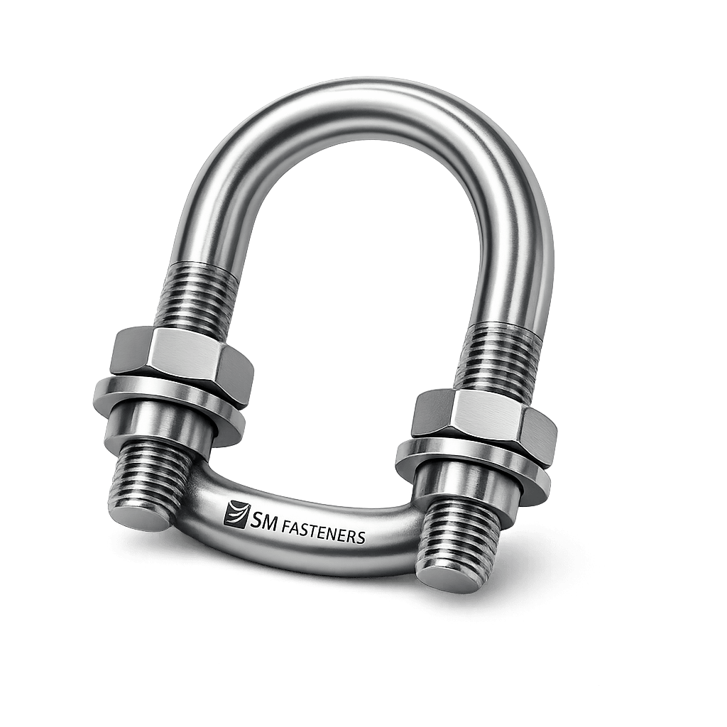
A U Bolt is a curved threaded fastening element designed primarily to secure cylindrical, structural, or irregular components to a supporting framework. Unlike conventional bolts that generate clamping force between flat interfaces, U bolts provide radial restraint combined with axial clamping.
They are widely deployed where:
- Circular members require restraint
- Dynamic vibration exists
- Thermal expansion must be accommodated
- Alignment stability is critical
Typical restrained components include:
- Pipes and process lines
- Tubular structures
- Structural steel sections
- Cable trays
- Exhaust systems
- Offshore risers
- Equipment frames
In engineered assemblies, U bolts function as load-transfer devices, not merely holding components but managing:
- Static loads
- Dynamic vibration loads
- Thermal movement
- Shock and fatigue stresses
1.2 Industrial Importance Across Sectors
Construction & Structural Steel
- Pipe supports
- Cable containment systems
- Structural bracing
- HVAC suspension
Oil & Gas (Upstream–Downstream)
- Pipeline anchoring
- Instrument tubing fixation
- Offshore deck piping
- Process skid assembly
Power Generation
- Boiler piping
- Turbine auxiliary systems
- Cooling water lines
Petrochemical & Chemical Processing
- Corrosion-resistant pipe restraint
- High-temperature line support
LNG & Offshore Platforms
- Cryogenic pipe stabilization
- Vibration-controlled supports
Heavy Equipment & Automotive
- Suspension assemblies
- Axle retention systems
Railways & Infrastructure
- Trackside utilities
- Signaling structures
Shipbuilding & Marine Systems
- Seawater piping
- Engine room installations
SM Fasteners supplies U bolts aligned with global EPC procurement requirements, ensuring interchangeability with international standards.
1.3 Engineering Classification
U bolts are categorized as:
| Category | Functional Objective |
|---|---|
| Pipe Support Fasteners | Load transfer without pipe deformation |
| Structural Clamp Fasteners | Rigid positioning |
| Suspension Fasteners | Vertical load carrying |
| Alignment Fasteners | Maintain geometry under vibration |
| Expansion-Allowing Fasteners | Permit thermal movement |
2. Technical Definition
2.1 Formal Engineering Definition
A U Bolt is defined as:
A bent threaded rod forming a “U” profile with two parallel threaded legs designed to secure round, square, or rectangular members against a mounting surface using nuts and washers.
2.2 Primary Components
- Crown (Bend Radius)
Contacts restrained member. - Legs
Parallel threaded sections transmitting load. - Threaded Ends
Provide preload via nut tightening. - Nuts & Washers
Distribute bearing pressure and generate clamping force.
2.3 Geometric Parameters
Key engineering dimensions:
| Symbol | Parameter | Engineering Significance |
|---|---|---|
| d | Rod diameter | Strength capacity |
| C | Inside width | Member accommodation |
| H | Leg length | Engagement depth |
| R | Bend radius | Stress distribution |
| P | Thread pitch | Load transfer efficiency |
| L | Overall length | Installation clearance |
2.4 Functional Behavior
Unlike straight bolts, U bolts:
- Apply distributed radial pressure
- Resist transverse motion
- Provide multi-directional restraint
- Operate under combined loading modes
3. Load Mechanics & Force Behavior
3.1 Load Types Acting on U Bolts
U bolts typically experience combined stress states:
| Load Type | Source |
|---|---|
| Tensile Load | Nut tightening preload |
| Shear Load | Pipe movement |
| Bending Stress | Curved geometry |
| Fatigue Load | Vibration |
| Thermal Stress | Expansion/contraction |
| Impact Load | Flow-induced vibration |
3.2 Force Transfer Mechanism
The load path follows:
- Nut torque generates preload.
- Preload produces clamping force.
- Friction resists movement.
- Load transfers to support structure.
Engineering Objective:
Maintain sufficient preload so operational loads never overcome frictional resistance.
3.3 Preload Concept
Preload is the most critical design parameter.
Where:
- = Preload force (N)
- = Applied torque (Nm)
- = Nut factor (≈0.18–0.25)
- = Nominal diameter (m)
Proper preload ensures:
- Joint stability
- Fatigue resistance
- Vibration immunity
3.4 Frictional Holding Capacity
The resistance against sliding:
Where:
- μ = friction coefficient
- Fp = preload
If operational load exceeds friction force → slip occurs.
3.5 Stress Distribution in the Bend
The curved region introduces:
- Stress concentration
- Plastic deformation risk
- Residual stresses
Engineering mitigation:
- Controlled bending radius
- Post-forming stress relief
- Proper heat treatment
SM Fasteners employs controlled forming practices ensuring uniform grain flow continuity, critical for fatigue resistance.
3.6 Torque–Tension Relationship
Only ~10–15% of applied torque generates preload.
Torque losses:
| Loss Source | Typical Share |
|---|---|
| Thread friction | 40% |
| Bearing surface friction | 45% |
| Useful preload | 15% |
Hence lubrication and coating selection directly influence performance.
3.7 Failure Modes in U Bolts
1. Fatigue Failure
Occurs under cyclic vibration.
Causes:
- Insufficient preload
- Poor surface finish
- Sharp bend radius
2. Yielding / Plastic Deformation
Result of overload or undersized diameter.
3. Shear Failure
Typically due to pipe sliding or impact load.
4. Hydrogen Embrittlement
Risk in high-strength carbon steels with electroplated coatings.
Mitigation:
- Baking treatment
- Mechanical galvanizing
- Controlled hardness limits
5. Stress Corrosion Cracking (SCC)
Common in:
- Chloride environments
- Offshore structures
- Chemical plants
Material selection becomes critical.
6. Thread Stripping
Occurs when engagement length is insufficient.
Recommended engagement:
4. Joint Design Principles
4.1 U Bolt vs Conventional Bolted Joint
| Parameter | Standard Bolt | U Bolt |
|---|---|---|
| Load Direction | Axial | Radial + Axial |
| Contact Surface | Flat | Cylindrical |
| Stress State | Uniform | Combined |
| Movement Control | Limited | High |
4.2 Design Objective
A correctly designed U bolt joint must achieve:
- Adequate preload
- Controlled contact pressure
- Zero relative motion
- No pipe ovalization
4.3 Pipe Support Design Approaches
Rigid Support
Used where movement must be eliminated.
Guide Support
Allows axial movement.
Sliding Support
Reduces thermal stress.
Spring Support
For vertical displacement systems.
4.4 Clamp Pressure Calculation
Contact pressure:
Where:
- Ac = contact area between pipe and bolt.
Excess pressure may deform thin-wall pipes.
4.5 Thermal Expansion Consideration
Thermal elongation:
Design must prevent excessive restraint causing:
- Pipe buckling
- Anchor overload
- Bolt fatigue
4.6 Vibration Design Guidelines
Recommended engineering practices:
- Use hardened washers
- Apply prevailing torque nuts
- Consider double-nut locking
- Maintain minimum preload ratio:
4.7 Installation Alignment Principles
Incorrect installation leads to premature failure.
Key requirements:
- Parallel leg alignment
- Uniform nut tightening
- Even washer seating
- Controlled torque application
4.8 Safety Factors
Typical engineering safety factors:
| Industry | Safety Factor |
|---|---|
| Structural Steel | 2.0 |
| Oil & Gas | 3.0 |
| Offshore | 3.5 |
| Dynamic Equipment | 4.0 |
4.9 Design Selection Workflow (Engineering Practice)
- Identify pipe OD or member geometry.
- Determine operational loads.
- Calculate required preload.
- Select diameter and material grade.
- Verify corrosion resistance.
- Confirm standard compliance.
- Specify coating system.
- Validate inspection requirements.
SM Fasteners supports project-specific engineering selection aligned with EPC procurement specifications and ISO 9001 traceability systems.
5. Product Types and Variants
5.1 Functional Classification of U Bolts
U bolts are engineered based on load behavior, installation geometry, and service environment. Selection directly influences joint reliability and lifecycle performance.
| Type | Geometry | Primary Application | Engineering Purpose |
|---|---|---|---|
| Round Bend U Bolt | Circular crown | Pipe supports | Uniform radial load distribution |
| Square U Bolt | Square bend | Structural beams | Edge restraint |
| Semi-Round U Bolt | Partial curvature | Automotive suspension | Controlled movement |
| Long Tangent U Bolt | Extended legs | Deep mounting | Increased thread engagement |
| Heavy Duty U Bolt | Larger diameter | Offshore & heavy loads | High tensile capacity |
| Anchor U Bolt | Embedded ends | Concrete foundations | Permanent anchoring |
| Exhaust U Bolt | Saddle clamp configuration | Automotive exhaust | Vibration resistance |
| PEEK U Bolt | Polymer construction | Electrical & chemical systems | Non-metallic isolation |
SM Fasteners manufactures both standardized and project-specific U bolt configurations, including engineered bends, customized leg lengths, and specialized thread forms.
5.2 Geometry-Based Design Variants
5.2.1 Round U Bolt
Most widely used configuration.
Advantages:
- Even stress distribution
- Reduced pipe indentation
- Suitable for pressure piping
Typical Industries:
- Oil & Gas
- Power plants
- Process industries
5.2.2 Square U Bolt
Designed for:
- Channel sections
- Rectangular frames
- Structural steel fixation
Engineering Feature:
- Prevents rotational movement.
5.2.3 Long Tangent U Bolt
Characteristics:
- Increased straight leg length before bend.
- Reduced bending stress concentration.
Preferred for:
- High-temperature pipelines
- Large insulation thickness
5.2.4 Heavy Series U BOLT
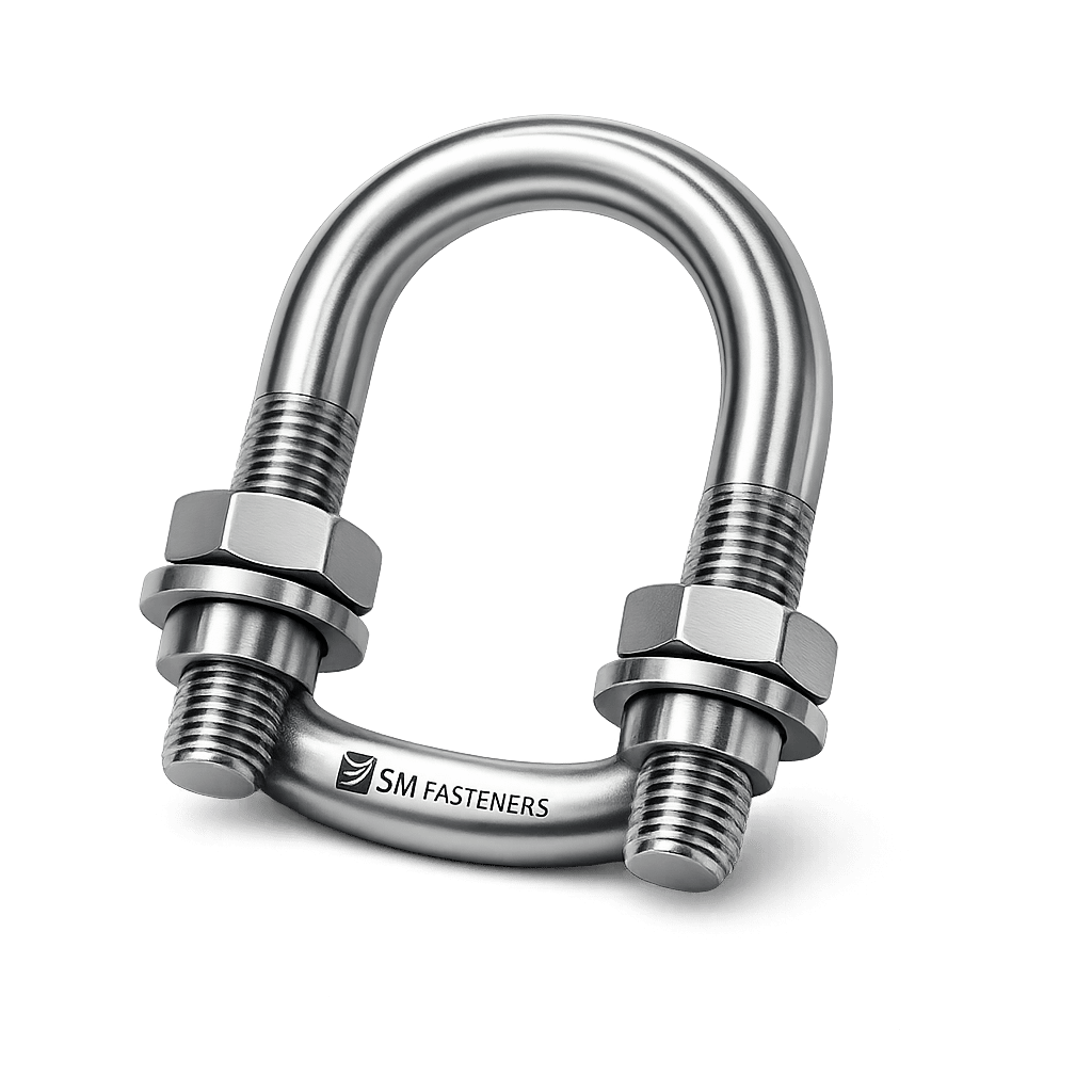
Designed for:
- High vibration systems
- Offshore modules
- Dynamic loading environments
Features:
- Larger rod diameter
- Higher preload capacity
5.2.5 Non-Metallic (PEEK) U Bolts
SM Fasteners provides PEEK fasteners where metallic contact is undesirable.
Applications:
- Electrical insulation
- Chemical exposure
- MRI equipment
- Semiconductor plants
Advantages:
- Non-conductive
- Chemical inertness
- Low thermal conductivity
- Zero galvanic corrosion risk
6. Dimensional Logic and Geometry Engineering
6.1 Governing Design Parameters
U bolt geometry is controlled by five critical dimensions:
| Parameter | Symbol | Function |
|---|---|---|
| Rod Diameter | d | Determines load capacity |
| Inside Width | C | Fits pipe OD |
| Inside Height | H | Installation clearance |
| Thread Length | b | Engagement strength |
| Bend Radius | R | Fatigue resistance |
6.2 Engineering Relationship Between Pipe OD and U Bolt Size
General selection rule:
Recommended clearance:
| Pipe Size | Clearance |
|---|---|
| ≤ 2″ | +2–3 mm |
| 3″–10″ | +3–6 mm |
| >10″ | +6–12 mm |
6.3 Bend Radius Engineering
Minimum bend radius:
Benefits:
- Reduced residual stress
- Improved fatigue life
- Better coating adhesion
6.4 Thread Engagement Requirements
Minimum effective engagement:
| Material | Engagement Length |
|---|---|
| Carbon Steel | 1 × diameter |
| Stainless Steel | 1.25 × diameter |
| Nickel Alloys | 1.5 × diameter |
| PEEK | 2 × diameter |
6.5 Standard Dimensional Specification Table (Metric Series)
Typical U Bolt Dimensions — Metric
| Nominal Size | Rod Dia (mm) | Inside Width C (mm) | Leg Length H (mm) | Thread Pitch | Bend Radius (mm) |
|---|---|---|---|---|---|
| M6 | 6 | 20–40 | 40–80 | 1.0 | 9 |
| M8 | 8 | 25–50 | 50–100 | 1.25 | 12 |
| M10 | 10 | 30–75 | 60–150 | 1.5 | 15 |
| M12 | 12 | 40–100 | 80–200 | 1.75 | 18 |
| M16 | 16 | 50–150 | 100–250 | 2.0 | 24 |
| M20 | 20 | 70–200 | 120–300 | 2.5 | 30 |
| M24 | 24 | 90–250 | 150–350 | 3.0 | 36 |
| M30 | 30 | 120–350 | 200–450 | 3.5 | 45 |
Dimensional tolerances maintained according to ISO tolerance systems under SM Fasteners’ ISO 9001 quality control framework.
7. International Standards & Compliance
7.1 Global Manufacturing Standards
U bolts are produced under multiple international systems depending on project specification.
| Standard | Region | Application |
|---|---|---|
| ISO 898 | International | Mechanical properties |
| ISO 965 | International | Thread tolerances |
| DIN 3570 | Germany | Pipe U bolts |
| DIN 976 | Germany | Thread standards |
| ASTM A307 | USA | General purpose |
| ASTM A193 | USA | High temperature/pressure |
| ASTM A320 | USA | Low temperature service |
| ASTM F1554 | USA | Anchor applications |
| BS 3974 | UK | Pipe supports |
| BS 4190 | UK | General fasteners |
SM Fasteners ensures interchangeability across ISO, DIN, ASTM, and BS systems, supporting multinational EPC procurement.
7.2 Thread Standards & Tolerances
Thread System Comparison
| Thread Type | Standard | Pitch Type | Typical Use |
|---|---|---|---|
| Metric Coarse | ISO 261 | Coarse | Structural |
| Metric Fine | ISO 262 | Fine | Dynamic loads |
| UNC | ASME B1.1 | Coarse | Heavy industry |
| UNF | ASME B1.1 | Fine | Automotive |
| BSW | BS 84 | Coarse | Legacy UK equipment |
| BSF | BS 84 | Fine | Precision assemblies |
Thread Tolerance Classes
| System | External Thread | Internal Thread |
|---|---|---|
| ISO Metric | 6g | 6H |
| UNC/UNF | 2A | 2B |
| Precision Fit | 4g6g | 4H |
7.3 Mechanical Property Classes
ISO Property Class System
| Property Class | Tensile Strength (MPa) | Yield Strength (MPa) | Application |
|---|---|---|---|
| 4.6 | 400 | 240 | Light duty |
| 5.8 | 500 | 400 | General use |
| 8.8 | 800 | 640 | Structural |
| 10.9 | 1040 | 940 | Heavy equipment |
| 12.9 | 1220 | 1100 | High strength assemblies |
ASTM Equivalent Mapping
| ISO Class | ASTM Equivalent |
|---|---|
| 4.6 | A307 |
| 8.8 | A325 equivalent range |
| 10.9 | A449 |
| High Temp | A193 B7 |
| Low Temp | A320 L7 |
7.4 Interchangeability Considerations
Critical procurement checks:
- Thread pitch compatibility
- Nut standard matching
- Washer hardness requirements
- Coating thickness allowance
- Load rating equivalence
Improper interchangeability may cause:
- Preload loss
- Thread galling
- Stress concentration
8. Proof Load & Tensile Strength Table
Typical Mechanical Capacity (Carbon Steel U Bolts)
| Size | Property Class | Proof Load (kN) | Min Tensile Load (kN) |
|---|---|---|---|
| M8 | 8.8 | 14 | 20 |
| M10 | 8.8 | 22 | 32 |
| M12 | 8.8 | 32 | 46 |
| M16 | 8.8 | 58 | 84 |
| M20 | 8.8 | 90 | 130 |
| M24 | 8.8 | 130 | 190 |
| M30 | 8.8 | 210 | 300 |
Values aligned with ISO 898 mechanical property requirements.
9. Weight Chart — SM Fasteners Reference Data
(Aligned with manufacturing output and export documentation.)
| Size | Weight / Piece (kg) | Weight / 100 pcs (kg) |
|---|---|---|
| M8 × 75 | 0.09 | 9 |
| M10 × 100 | 0.16 | 16 |
| M12 × 120 | 0.28 | 28 |
| M16 × 150 | 0.55 | 55 |
| M20 × 200 | 1.05 | 105 |
| M24 × 250 | 1.85 | 185 |
| M30 × 300 | 3.10 | 310 |
Weight verification supports:
- Shipping calculations
- Structural load planning
- Export packing documentation
10. Engineering Selection Logic for EPC Procurement
Procurement engineers evaluate U bolts using:
- Load requirement verification
- Applicable international standard
- Material compatibility
- Environmental exposure
- Required certification level
- Coating system
- Inspection class
SM Fasteners integrates these requirements within an ISO 9001 controlled manufacturing and traceability system, enabling supply for global infrastructure and energy projects.
11. Material Grades and Selection Criteria
11.1 Engineering Material Philosophy
Material selection for U bolts directly determines:
- Load-bearing capability
- Fatigue resistance
- Corrosion performance
- Temperature stability
- Service life reliability
Unlike standard bolts, U bolts undergo cold deformation during bending, requiring materials with:
- High ductility
- Stable grain structure
- Controlled hardness
- Good notch toughness
SM Fasteners manufactures U bolts across a full industrial material spectrum aligned with EPC and OEM specifications.
11.2 Industrial Material Range
Carbon Steel
| Grade | Standard | Typical Use |
|---|---|---|
| IS 2062 / ASTM A36 | Structural | General construction |
| ASTM A307 | General purpose | Pipe supports |
| ASTM A105 | Forged carbon steel | Pressure applications |
| ASTM A193 B7 | High strength | Oil & Gas / Power |
Characteristics:
- Economical
- High strength
- Requires coating protection
Alloy Steel
| Grade | Key Feature | Application |
|---|---|---|
| ASTM A193 B7M | Controlled hardness | Sour service |
| ASTM A320 L7 | Low temperature toughness | LNG systems |
| EN 42CrMo4 | High fatigue strength | Heavy equipment |
Stainless Steel
| Grade | Equivalent | Properties |
|---|---|---|
| SS304 | 1.4301 | General corrosion resistance |
| SS316 | 1.4401 | Marine & chemical |
| SS316L | Low carbon | Weld stability |
| SS321 | Ti stabilized | High temperature |
| SS904L | Super austenitic | Acid resistance |
Duplex & Super Duplex Stainless Steel
| Grade | Standard | Application |
|---|---|---|
| Duplex 2205 | UNS S31803 | Offshore pipelines |
| Super Duplex 2507 | UNS S32750 | Seawater systems |
Advantages:
- High strength
- Excellent SCC resistance
- Reduced weight requirement
Nickel Alloys
SM Fasteners supports critical projects requiring advanced alloys.
| Alloy | Environment |
|---|---|
| Inconel 625 | High temperature |
| Incoloy 825 | Acidic service |
| Hastelloy C276 | Aggressive chemicals |
| Monel 400 | Marine exposure |
| Nickel 200 | Caustic alkali service |
| SMO 254 | Chloride environments |
Engineering Polymer — PEEK U Bolts
PEEK fasteners are applied where metals fail due to:
- Electrical conductivity
- Chemical attack
- Magnetic interference
Properties:
- Continuous service temperature ≈ 250°C
- Excellent chemical resistance
- Lightweight
- Non-galling threads
Typical industries:
- Semiconductor manufacturing
- Medical equipment
- Electrical systems
- Chemical processing plants
11.3 Material Comparison Table
| Material | UTS (MPa) | Yield (MPa) | Corrosion Resistance | Relative Cost | Typical Application |
|---|---|---|---|---|---|
| Carbon Steel | 400–800 | 250–640 | Low | Low | Structural |
| Alloy Steel B7 | 860 | 720 | Moderate | Medium | Oil & Gas |
| SS304 | 515 | 205 | Good | Medium | General industry |
| SS316 | 515 | 205 | Excellent | Medium-High | Marine |
| Duplex 2205 | 620 | 450 | Very High | High | Offshore |
| Super Duplex | 800 | 550 | Extreme | Very High | Seawater |
| Inconel 625 | 930 | 480 | Extreme | Premium | High temp |
| PEEK | 100 | 90 | Chemical inert | High | Electrical |
11.4 Temperature Capability Range
| Material | Service Temperature |
|---|---|
| Carbon Steel | −20°C to 400°C |
| A320 L7 | −101°C |
| Stainless Steel | −196°C to 600°C |
| Duplex | −50°C to 300°C |
| Nickel Alloys | Up to 1000°C |
| PEEK | Up to 250°C |
11.5 NACE MR0175 / ISO 15156 Compliance
Required for sour service containing H₂S.
Engineering controls:
- Hardness ≤ 22 HRC (carbon/alloy steel)
- Controlled heat treatment
- Material traceability
- Verified chemical composition
SM Fasteners supports NACE-compliant production routes for oil & gas environments.
12. Heat Treatment Processes
12.1 Objectives of Heat Treatment
Heat treatment modifies:
- Strength
- Toughness
- Residual stress
- Fatigue life
Critical for U bolts because bending introduces localized stresses.
12.2 Common Heat Treatment Methods
Normalizing
Refines grain structure.
Used for:
- Carbon steel U bolts
- Structural applications
Quenching & Tempering
Process:
- Austenitizing
- Rapid quench
- Controlled tempering
Produces:
- High tensile strength
- Balanced toughness
Applied to:
- ASTM A193 B7
- Property class 10.9
Solution Annealing (Stainless Steel)
Purpose:
- Restore corrosion resistance
- Remove carbide precipitation
Temperature:
≈ 1040–1100°C followed by rapid cooling.
Stress Relieving
Performed after bending operation.
Benefits:
- Reduces residual stress
- Prevents fatigue cracking
12.3 Hardness Limits (Engineering Control)
| Application | Maximum Hardness |
|---|---|
| General Service | 32 HRC |
| Sour Service | 22 HRC |
| High Strength | 39 HRC |
| Stainless Steel | Controlled by grade |
13. End-to-End Manufacturing Workflow
13.1 Raw Material Procurement & Verification
Process begins with certified raw material.
Mandatory controls:
- Mill Test Certificate (MTC)
- Heat number identification
- Spectrochemical analysis
- PMI verification
Traceability maintained under ISO 9001 system.
13.2 Material Preparation
Steps:
- Bar cutting
- Surface cleaning
- Straightness inspection
- Diameter verification
13.3 Forming Process — Forging vs Bending
Cold Bending (Most Common)
Advantages:
- Improved grain flow
- Higher fatigue resistance
- Dimensional consistency
Hot Forming
Used for:
- Large diameter U bolts
- Nickel alloys
- Heavy-duty applications
Forged U Bolts
Applied where extreme load reliability is required.
13.4 Thread Production
Thread Rolling (Preferred)
Benefits:
- Compressive residual stress
- Increased fatigue life
- Improved surface finish
- Higher strength threads
Thread Cutting
Used when:
- Large diameters
- Exotic alloys
- Small production batches
13.5 Dimensional Machining & Finishing
Operations include:
- Leg straightening
- Thread gauging
- Crown dimension inspection
- Burr removal
13.6 Heat Treatment Integration
Heat treatment may occur:
- Before threading
- After bending
- Final stress relief stage
Each stage documented and traceable.
13.7 Identification & Traceability
SM Fasteners maintains:
- Heat number marking
- Batch coding
- Inspection trace records
- Manufacturing route card
14. Surface Finishing & Coatings
14.1 Purpose of Surface Engineering
Surface treatment protects against:
- Corrosion
- Galling
- Seizure
- Wear
- Hydrogen embrittlement
14.2 Common Coating Systems
| Coating | Thickness | Corrosion Resistance | Typical Use |
|---|---|---|---|
| Black Oxide | 1 µm | Low | Indoor |
| Zinc Plated | 8–12 µm | Moderate | Construction |
| Hot Dip Galvanized | 70–100 µm | High | Outdoor |
| Mechanical Galvanized | 40–70 µm | High | High strength bolts |
| PTFE/Xylan | 20–40 µm | Chemical resistant | Oil & Gas |
| Dacromet/Geomet | 8–12 µm | Excellent | Automotive |
| Fluoropolymer | Variable | Extreme | Offshore |
| Passivation (SS) | — | Restores chromium layer | Stainless steel |
14.3 Surface Finish Performance Comparison
| Finish | Salt Spray Resistance | Friction Stability | Hydrogen Embrittlement Risk |
|---|---|---|---|
| Zinc Electroplated | Medium | Moderate | High |
| HDG | High | Variable | Low |
| PTFE Coated | Very High | Excellent | None |
| Stainless Passive | Excellent | Stable | None |
14.4 Coating Selection vs Environment
| Environment | Recommended Finish |
|---|---|
| Indoor industrial | Zinc plated |
| Marine atmosphere | HDG / SS316 |
| Offshore splash zone | Duplex / PTFE |
| Chemical plant | Nickel alloy / Fluoropolymer |
| H₂S service | Mechanical galvanized |
| Cryogenic | Stainless steel |
14.5 Galvanizing Dimensional Compensation
Coating thickness affects thread fit.
Engineering practice:
- Oversize thread allowance
- Class 6AZ tolerance for HDG
- Nut tapping after galvanizing
14.6 Lubrication & Assembly Considerations
Proper lubrication ensures predictable preload.
Common lubricants:
- Molybdenum disulfide
- PTFE dry film
- Anti-seize compounds
Nut factor varies significantly with coating type and must be included in torque calculations.
14.7 Packaging Surface Protection
SM Fasteners uses industrial packaging systems:
- VCI corrosion protection
- Thread protectors
- Export moisture barriers
- Batch identification labels
15. Inspection & Quality Control
15.1 Quality Philosophy
U bolts operate in load-critical restraint systems, meaning failure can result in:
- Pipeline displacement
- Structural instability
- Equipment shutdown
- Safety hazards
Therefore, inspection extends beyond dimensional checks to include material verification, mechanical validation, and traceability control.
SM Fasteners integrates inspection through an ISO 9001 certified quality management system aligned with EPC and third-party inspection requirements.
15.2 Incoming Material Inspection
Mandatory verification before manufacturing:
| Inspection | Method | Objective |
|---|---|---|
| Mill Test Certificate | EN 10204 3.1 | Chemical & mechanical verification |
| Heat Number Check | Traceability | Batch control |
| Chemical Analysis | Spectrometer | Alloy confirmation |
| PMI Testing | XRF/Optical | Material authentication |
| Visual Inspection | Surface check | Defect elimination |
15.3 In-Process Inspection
During manufacturing:
- Bend radius verification
- Leg parallelism measurement
- Thread rolling inspection
- Diameter tolerance verification
- Surface defect inspection
15.4 Dimensional Inspection Parameters
| Parameter | Inspection Tool |
|---|---|
| Rod Diameter | Micrometer |
| Inside Width | Vernier caliper |
| Leg Length | Height gauge |
| Thread Pitch | Thread gauge |
| Thread Class | Go/No-Go gauge |
| Bend Radius | Template gauge |
15.5 Mechanical Testing
Required for critical applications.
| Test | Standard | Purpose |
|---|---|---|
| Tensile Test | ISO 898 / ASTM | Strength validation |
| Proof Load Test | ISO 898 | Elastic limit |
| Hardness Test | Rockwell/Brinell | Heat treatment verification |
| Bend Test | Internal QC | Forming integrity |
| Impact Test | ASTM E23 | Low-temperature service |
15.6 Non-Destructive Testing (NDT)
Applied based on project specification.
| Method | Detection |
|---|---|
| Magnetic Particle Testing | Surface cracks |
| Dye Penetrant Testing | Micro defects |
| Ultrasonic Testing | Internal flaws |
| Eddy Current Testing | Surface discontinuities |
15.7 Positive Material Identification (PMI)
Mandatory for:
- Duplex stainless steel
- Nickel alloys
- Sour service applications
Ensures:
- Correct alloy supply
- Project compliance
- Prevention of material mix-up
15.8 Documentation & Certification
Typical documentation supplied by SM Fasteners:
- EN 10204 3.1 / 3.2 MTC
- Heat treatment charts
- Coating thickness reports
- Dimensional inspection reports
- Mechanical test certificates
- Compliance certificate (CoC)
16. Mechanical Properties Table (Grade-Wise)
| Property Class | Tensile Strength MPa | Yield Strength MPa | Hardness Range | Typical Industry |
|---|---|---|---|---|
| 4.6 | 400 | 240 | 120–180 HB | Light structures |
| 5.8 | 500 | 400 | 150–220 HB | General engineering |
| 8.8 | 800 | 640 | 22–32 HRC | Structural |
| 10.9 | 1040 | 940 | 32–39 HRC | Heavy equipment |
| 12.9 | 1220 | 1100 | 39–44 HRC | Dynamic assemblies |
17. Corrosion Resistance vs Environment
| Environment | Carbon Steel | SS304 | SS316 | Duplex | Nickel Alloy | PEEK |
|---|---|---|---|---|---|---|
| Indoor Industrial | Good | Excellent | Excellent | Excellent | Excellent | Excellent |
| Marine Atmosphere | Poor | Moderate | Excellent | Excellent | Excellent | Excellent |
| Seawater Immersion | Poor | Poor | Good | Excellent | Excellent | Excellent |
| Acidic Chemical | Poor | Moderate | Good | Excellent | Excellent | Excellent |
| H₂S Service | Limited | Good | Good | Excellent | Excellent | Excellent |
| Cryogenic | Moderate | Excellent | Excellent | Excellent | Excellent | Good |
18. Tightening Torque Chart
(Typical values — lubricated condition, nut factor ≈0.18)
| Size | Grade 8.8 Torque (Nm) | Grade 10.9 Torque (Nm) |
|---|---|---|
| M8 | 25 | 35 |
| M10 | 49 | 70 |
| M12 | 85 | 120 |
| M16 | 210 | 300 |
| M20 | 410 | 580 |
| M24 | 710 | 1000 |
| M30 | 1400 | 1950 |
Torque must always be validated against coating friction coefficient.
19. Preload Calculation — Worked Engineering Example
Given
- U Bolt Size: M16
- Applied Torque: 210 Nm
- Nut Factor K = 0.20
- Diameter d = 16 mm = 0.016 m
Preload Equation
\
Result:
Approximate preload = 65.6 kN
Frictional Holding Capacity
Assuming μ = 0.3:
This represents available resistance against pipe sliding.
20. Thread Standards & Tolerance Table
| Thread System | Standard | Tolerance Class | Application |
|---|---|---|---|
| ISO Metric | ISO 965 | 6g / 6H | Global EPC |
| UNC | ASME B1.1 | 2A / 2B | Oil & Gas |
| UNF | ASME B1.1 | 2A / 2B | Automotive |
| BSW | BS 84 | Medium Fit | Legacy systems |
| BSF | BS 84 | Fine Fit | Precision equipment |
21. Surface Finish Performance Comparison
| Surface Finish | Corrosion Protection | Friction Control | Offshore Suitability | Maintenance |
|---|---|---|---|---|
| Black Oxide | Low | Stable | No | High |
| Zinc Plated | Moderate | Good | Limited | Medium |
| HDG | High | Variable | Good | Low |
| PTFE/Xylan | Very High | Excellent | Excellent | Very Low |
| Passivated Stainless | Excellent | Stable | Excellent | Minimal |
22. Weight Reference Chart — SM Fasteners Production Data
| Size | Approx Weight / Piece (kg) | Weight / 100 pcs (kg) |
|---|---|---|
| M8 × 75 | 0.09 | 9 |
| M10 × 100 | 0.16 | 16 |
| M12 × 120 | 0.28 | 28 |
| M16 × 150 | 0.55 | 55 |
| M20 × 200 | 1.05 | 105 |
| M24 × 250 | 1.85 | 185 |
| M30 × 300 | 3.10 | 310 |
Supports:
- Export logistics
- Structural design loads
- Procurement estimation
23. Industry Applications Mapping
Construction & Structural Steel
- Pipe rack supports
- Structural anchoring
- HVAC suspension
Oil & Gas Industry
Upstream
- Wellhead piping
- Offshore decks
Midstream
- Pipeline supports
- Compressor stations
Downstream
- Refinery piping systems
- Chemical process lines
NACE-compliant materials supplied where required.
Power Generation
- Boiler assemblies
- Cooling water systems
- Turbine auxiliary piping
Petrochemical & Chemical Processing
- Acid-resistant supports
- High-temperature piping
LNG & Cryogenic Systems
- A320 L7 U bolts
- Stainless steel cryogenic fastening
Automotive & Heavy Equipment
- Axle mounting
- Suspension retention systems
Railways & Infrastructure
- Cable containment
- Utility mounting systems
Shipbuilding & Offshore
- Seawater piping
- Engine room assemblies
- Deck-mounted utilities
PEEK Fastener Applications
Used where metallic fasteners are unsuitable:
- Electrical isolation systems
- Semiconductor manufacturing
- Chemical dosing equipment
- MRI and instrumentation assemblies
24. Failure Prevention & Reliability Engineering
Fatigue Prevention
- Maintain adequate preload
- Rolled threads preferred
- Smooth bend radius
Hydrogen Embrittlement Control
- Avoid electroplating for high-strength grades
- Post-plate baking
- Mechanical galvanizing
Stress Corrosion Prevention
- Select duplex or nickel alloys
- Apply fluoropolymer coatings
- Avoid tensile overstress
25. Export Capability & Global Supply Readiness
SM Fasteners supports international project procurement with controlled export systems.
25.1 Industrial Packaging
- VCI anti-corrosion wrapping
- Thread protection caps
- Moisture barrier packaging
- Batch identification labeling
25.2 Export Crating
- ISPM-15 compliant wooden crates
- Sea-freight ready packaging
- Palletized container loading
- Shock-resistant packing
25.3 Documentation Package
Typical EPC shipment includes:
- Material Test Certificates (EN 10204 3.1 / 3.2)
- Inspection reports
- Heat treatment records
- Coating reports
- Dimensional inspection records
- Certificate of Conformance
- Packing list & traceability sheet
26. Engineering Procurement Readiness — SM Fasteners
SM Fasteners manufacturing capability demonstrates:
- Compliance with ISO 9001 quality systems
- Certified MSME industrial production
- UKAF accredited processes
- Full international standards alignment (ISO / ASTM / DIN / BS)
- Advanced material manufacturing including Duplex, Nickel Alloys, and PEEK
- Custom-engineered U bolt solutions for EPC and OEM projects
✅ COMPLETE ENGINEERING REFERENCE
Total Coverage Delivered
✔ Functional engineering principles
✔ International standards compliance
✔ Material science & metallurgy
✔ Manufacturing methodology
✔ Surface engineering
✔ Inspection & QA systems
✔ Complete engineering tables
✔ EPC procurement readiness
✔ Global export capability