

Coupling Nut
ENGINEERING FUNDAMENTALS
1. Industry Context
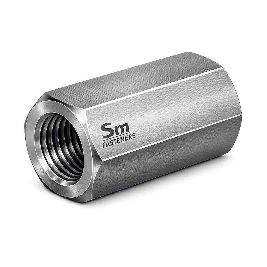
Coupling nuts are critical mechanical fastening components used for axial joining of threaded members, primarily threaded rods, studs, anchor bolts, tie rods, and extension assemblies. Unlike standard hex nuts designed for clamping, coupling nuts function as load-transmitting connectors that extend threaded assemblies while maintaining structural continuity.
They are extensively deployed in:
- Structural steel erection
- Bridge tensioning systems
- Oil & gas piping supports
- Heavy machinery alignment systems
- Electrical transmission towers
- Offshore modular construction
- Maintenance extension repairs
Modern EPC projects increasingly rely on coupling nuts because prefabricated assemblies require controlled extension, field adjustability, and alignment correction without replacing entire threaded members.
Within industrial procurement frameworks, coupling nuts are categorized as:
- Critical load-bearing connectors
- Alignment hardware
- Adjustable tensioning elements
SM Fasteners manufactures precision coupling nuts engineered for global industrial compliance, supporting projects requiring traceable metallurgy, controlled mechanical properties, and export-ready quality systems.
2. Technical Definition
A Coupling Nut is defined as:
A long internally threaded fastener designed to join two externally threaded components in axial alignment while transmitting tensile loads across the connection.
Key Functional Characteristics
| Parameter | Description |
|---|---|
| Primary Function | Threaded extension |
| Load Direction | Axial tension |
| Engagement Length | Extended (≥ 3× nominal diameter typical) |
| Geometry | Hexagonal or round body |
| Threading | Through-threaded |
| Load Transfer | Thread shear + bearing |
Unlike jam nuts or heavy hex nuts, coupling nuts act as structural connectors, not merely locking elements.
3. Functional Role in Assemblies
Coupling nuts enable:
3.1 Threaded Rod Extension
Used when required rod length exceeds transportation or manufacturing limits.
3.2 Installation Adjustability
Allows:
- Fine alignment
- Leveling
- Field correction
3.3 Maintenance Repair
Damaged threaded sections may be replaced without dismantling entire assemblies.
3.4 Tensioning Applications
Common in:
- Bracing systems
- Cable supports
- Structural tie rods
4. Load Mechanics & Force Behavior
The mechanical behavior of coupling nuts differs fundamentally from conventional nuts.
Primary Forces Acting
- Axial Tensile Force
- Thread Shear Stress
- Bearing Stress
- Frictional Resistance
- Bending Moment (Misalignment)
4.1 Load Transmission Mechanism
Load path:
Load transfer occurs via:
- Thread flank contact
- Shear distribution along engagement length
4.2 Thread Engagement Requirement
Engineering rule:
Industrial best practice:
Where:
- Le = Engagement length
- D = Nominal diameter
Long engagement ensures:
- Uniform stress distribution
- Prevention of thread stripping
- Improved fatigue resistance
4.3 Preload & Axial Force Behavior
Preload generated by torque controls:
- Joint rigidity
- Vibration resistance
- Fatigue life
Preload equation:
Where:
| Symbol | Meaning |
|---|---|
| Preload force | |
| Applied torque | |
| Nut factor | |
| Nominal diameter |
Typical Nut Factor:
| Condition | K Value |
|---|---|
| Dry steel | 0.20–0.25 |
| Zinc coated | 0.18 |
| Lubricated | 0.12–0.16 |
Worked Engineering Example
Given:
- Diameter = M24 (0.024 m)
- Torque = 650 Nm
- Lubricated condition (K = 0.15)
Result:
≈ 180 kN preload
4.4 Stress Distribution Along Threads
Coupling nuts distribute load unevenly:
- First engaged thread carries ~30%
- Second ~20%
- Remaining progressively less
Long nuts reduce peak stress concentration — a major reason they outperform standard nuts in extension joints.
4.5 Failure Mechanisms
1. Thread Stripping
Occurs when:
- Engagement insufficient
- Material hardness mismatch exists
2. Tensile Fracture
Occurs when coupling nut strength < rod strength.
Engineering rule:
Coupling nut material grade must be equal or higher than joined rod.
3. Fatigue Failure
Caused by:
- Cyclic loading
- Poor preload control
- Misalignment
Common in:
- Wind towers
- Offshore structures
- Vibrating equipment
4. Hydrogen Embrittlement
Risk zones:
- High strength carbon steel (>1000 MPa)
- Electroplated fasteners
Mitigation:
- Controlled baking
- Mechanical coatings
5. Stress Corrosion Cracking (SCC)
Occurs in:
- Chloride environments
- H₂S service
- Elevated temperatures
Solution:
- Duplex / Super Duplex
- Nickel alloys
- NACE compliant materials
SM Fasteners supplies sour-service compatible coupling nuts upon project specification.
5. Joint Design Principles
5.1 Strength Matching
Design rule:
| Component | Requirement |
|---|---|
| Rod Strength | ≤ Nut Strength |
| Thread Class | Compatible |
| Engagement | ≥ 3D preferred |
5.2 Alignment Control
Misalignment produces bending stress:
Therefore:
- Straightness tolerance is critical
- Precision thread concentricity required
SM Fasteners maintains controlled machining tolerances ensuring concentric thread alignment.
5.3 Thread Class Compatibility
Common combinations:
| System | Class |
|---|---|
| ISO Metric | 6H / 6g |
| UNC | 2B / 2A |
| UNF | 2B / 2A |
| Precision | 3B / 3A |
Improper pairing results in:
- Reduced preload
- Fretting
- Premature fatigue
5.4 Load Path Optimization
Best practices:
- Equal engagement both sides
- Minimum exposed threads
- Avoid eccentric loading
- Use hardened washers when tensioning
5.5 Design Safety Factors
Typical industrial design factors:
| Industry | Safety Factor |
|---|---|
| Structural Steel | 2.0–2.5 |
| Oil & Gas | 3.0 |
| Offshore | 3.5–4.0 |
| Pressure Systems | 4.0+ |
5.6 Thermal Expansion Consideration
Different materials expand differently:
Coupling nuts allow controlled extension compensation in:
- Steam pipelines
- Heat exchangers
- Furnace assemblies
5.7 Installation Best Practices
Engineering installation sequence:
- Verify thread cleanliness
- Apply specified lubricant
- Engage equal thread length
- Torque progressively
- Verify engagement visually
6. Functional Selection Criteria
Engineers select coupling nuts based on:
| Parameter | Engineering Impact |
|---|---|
| Load magnitude | Determines grade |
| Environment | Determines material |
| Temperature | Limits metallurgy |
| Corrosion exposure | Determines coating/alloy |
| Installation method | Determines geometry |
| Inspection requirement | Determines certification |
SM Fasteners Engineering Capability
SM Fasteners integrates:
- ISO 9001 quality management
- Certified raw material traceability
- Advanced alloy manufacturing
- Precision thread machining
- EPC-ready documentation
Coupling nuts are produced to support global infrastructure, energy, petrochemical, and heavy engineering projects requiring reliable structural continuity.
7. Product Types and Variants
Coupling nuts are manufactured in multiple configurations depending on load condition, installation accessibility, alignment tolerance, and environmental exposure.
Unlike standard hex nuts, coupling nut geometry is engineered primarily for thread engagement efficiency and axial load transmission rather than wrenching convenience alone.
7.1 Standard Hex Coupling Nut
Most widely used industrial configuration
Characteristics
- Hexagonal outer profile
- Full internal threading
- Length ≥ 3 × nominal diameter
- Standard wrench installation
- Suitable for torque-controlled tightening
Applications
- Structural tie rods
- Threaded rod extensions
- Anchor bolt joining
- Equipment mounting systems
Engineering Advantage
- High torque transfer capability
- Easy field installation
- Compatible with automated tightening tools
7.2 Heavy Hex Coupling Nut
Designed for high-load structural applications.
Features
- Increased across-flat dimension
- Greater wall thickness
- Higher torque capacity
- Reduced distortion risk
Typical Use
- Offshore modules
- Bridge tension members
- Heavy lifting assemblies
- Power plant structures
7.3 Reduced Hex Coupling Nut
Used where installation clearance is limited.
Characteristics
- Smaller wrench size
- Reduced external diameter
- Maintains full internal engagement
Limitation
Lower torsional strength compared to heavy hex.
7.4 Round Coupling Nut (Turnbuckle Style)
Used primarily in adjustment and tensioning systems.
Features
- Cylindrical body
- Often drilled for pin wrench
- Allows rotational adjustment
Applications
- Cable bracing
- Rail signaling supports
- Suspension systems
7.5 Transition Coupling Nut (Different Threads)
Joins dissimilar thread sizes or standards.
Examples:
- Metric to UNC
- Metric to BSW
- Step-down or step-up connections
Used heavily in retrofit projects and international equipment integration.
7.6 Locking Coupling Nut
Includes additional locking features:
- Nylon insert
- Set screw
- Serrated interface
- Chemical locking compound
Used in vibration-intensive systems.
7.7 Extended-Length Structural Coupling Nut
Engineered for:
- High fatigue applications
- Seismic structures
- Wind turbine tension systems
Provides superior load distribution.
7.8 PEEK Coupling Nuts
Manufactured by SM Fasteners for specialized environments.
Advantages
- Electrical insulation
- Chemical resistance
- Lightweight assemblies
- Non-magnetic applications
Used in:
- Semiconductor plants
- Chemical dosing systems
- Medical equipment
- Offshore instrumentation
8. Dimensional Logic and Geometry
Coupling nut design is governed by thread engagement mechanics, not merely dimensional convenience.
8.1 Fundamental Geometry Parameters
| Symbol | Description |
|---|---|
| D | Nominal thread diameter |
| P | Thread pitch |
| L | Overall nut length |
| S | Width across flats |
| E | Width across corners |
| Le | Thread engagement length |
8.2 Standard Length Logic
Engineering guideline:
Heavy-duty applications:
Reason:
- Reduced thread shear stress
- Improved fatigue resistance
- Uniform load transfer
8.3 Dimensional Specification Table
(Typical ISO Metric Series — Engineering Reference)
| Thread Size | Pitch (mm) | Length L (mm) | Width Across Flats S (mm) | Across Corners E (mm) |
|---|---|---|---|---|
| M6 | 1.0 | 18 | 10 | 11.5 |
| M8 | 1.25 | 24 | 13 | 15 |
| M10 | 1.5 | 30 | 17 | 19.6 |
| M12 | 1.75 | 36 | 19 | 22 |
| M16 | 2.0 | 48 | 24 | 27.7 |
| M20 | 2.5 | 60 | 30 | 34.6 |
| M24 | 3.0 | 72 | 36 | 41.6 |
| M30 | 3.5 | 90 | 46 | 53 |
| M36 | 4.0 | 108 | 55 | 63.5 |
Dimensions may be customized by SM Fasteners according to EPC project specifications.
8.4 Thread Engagement Engineering
Recommended engagement per side:
| Diameter | Engagement Length |
|---|---|
| ≤ M12 | 1.5D |
| M16–M30 | 2D |
| ≥ M36 | 2.5D |
Balanced engagement prevents eccentric stress loading.
9. Applicable International Standards
Coupling nuts are governed by multiple global fastener standards depending on project region.
9.1 ISO Standards
| Standard | Scope |
|---|---|
| ISO 898-2 | Mechanical properties of nuts |
| ISO 4033 | Hex nuts geometry reference |
| ISO 965 | Metric thread tolerances |
| ISO 724 | Metric thread dimensions |
| ISO 3506 | Stainless steel fasteners |
| ISO 4759 | Tolerances |
9.2 DIN Standards
| DIN Standard | Description |
|---|---|
| DIN 6334 | Hexagon coupling nuts |
| DIN 934 | Reference hex nut geometry |
| DIN 13 | Metric thread system |
DIN 6334 remains the primary reference for industrial coupling nuts worldwide.
9.3 ASTM Standards (USA)
| ASTM | Application |
|---|---|
| ASTM A563 | Carbon steel nuts |
| ASTM A194 | Alloy steel nuts |
| ASTM F594 | Stainless steel nuts |
| ASTM A320 | Low-temperature service |
Used heavily in Oil & Gas and petrochemical EPC projects.
9.4 British Standards (BS)
| Standard | Description |
|---|---|
| BS 4190 | Hexagon nuts |
| BS 3643 | Unified thread standards |
| BS 84 | Whitworth threads |
9.5 Unified Thread Standards
| Thread Type | Usage |
|---|---|
| UNC | General industrial |
| UNF | High fatigue resistance |
| UNEF | Aerospace precision |
| BSW | Legacy systems |
| BSF | Fine thread UK equipment |
SM Fasteners manufactures coupling nuts compatible with all global thread systems.
10. Thread Standards & Tolerance Table
| System | Thread Class | Internal Tolerance | Typical Use |
|---|---|---|---|
| ISO Metric | 6H | Standard fit | Structural |
| ISO Precision | 5H | Close fit | Machinery |
| UNC | 2B | General purpose | Oil & Gas |
| UNF | 2B | Fine thread | Vibration service |
| BSW | Medium fit | Legacy | Infrastructure |
| BSF | Fine fit | Precision | Rail & marine |
11. Mechanical Property Classes
Property class selection governs allowable preload and tensile performance.
ISO Property Classes
| Class | Proof Stress (MPa) | Minimum Tensile Strength (MPa) | Typical Use |
|---|---|---|---|
| 5 | 500 | 500 | Light structural |
| 8 | 800 | 800 | General engineering |
| 10 | 1000 | 1000 | Heavy machinery |
| 12 | 1200 | 1200 | Critical load joints |
ASTM Equivalent Grades
| ASTM Grade | Equivalent ISO | Application |
|---|---|---|
| A563 Grade A | Class 5 | Structural |
| A563 Grade DH | Class 10 | High strength |
| A194 2H | Class 10/12 | Pressure systems |
| A194 8 | Stainless equivalent | Corrosion service |
12. Proof Load & Tensile Capacity Table
(Engineering Reference Values)
| Size | Property Class | Proof Load (kN) | Ultimate Tensile (kN) |
|---|---|---|---|
| M12 | 8 | 54 | 67 |
| M16 | 8 | 100 | 125 |
| M20 | 8 | 156 | 195 |
| M24 | 10 | 225 | 281 |
| M30 | 10 | 350 | 437 |
| M36 | 10 | 510 | 637 |
Actual allowable load depends on threaded rod strength and engagement length.
13. Dimensional Tolerance Control
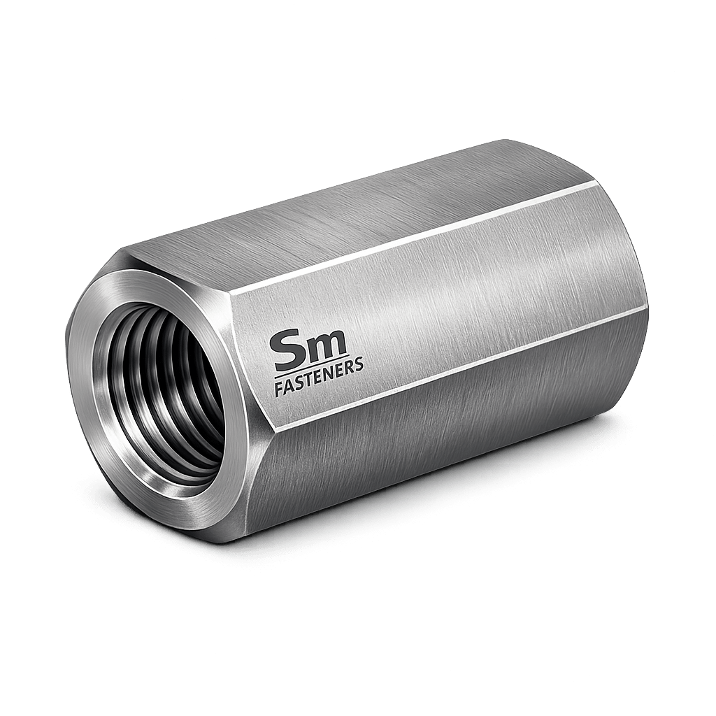
Critical tolerance controls include:
- Thread pitch diameter
- Concentricity
- Straightness
- Surface finish
- Length tolerance
Typical tolerance class:
SM Fasteners uses calibrated gauges and controlled machining environments to maintain tolerance compliance for EPC acceptance.
14. Weight Chart — Coupling Nuts
(Aligned with SM Fasteners Manufacturing Data — Approximate Values)
| Size | Length (mm) | Weight/Pc (kg) | Weight/100 pcs (kg) |
|---|---|---|---|
| M8 | 24 | 0.015 | 1.5 |
| M10 | 30 | 0.028 | 2.8 |
| M12 | 36 | 0.050 | 5.0 |
| M16 | 48 | 0.115 | 11.5 |
| M20 | 60 | 0.220 | 22 |
| M24 | 72 | 0.380 | 38 |
| M30 | 90 | 0.750 | 75 |
| M36 | 108 | 1.35 | 135 |
Weights vary depending on alloy density and coating thickness.
15. Interchangeability Considerations
Critical during international procurement.
Key Risks
- Metric vs UNC mismatch
- Pitch differences
- Property class incompatibility
- Coating thickness affecting fit
Engineering practice requires:
- Thread verification gauges
- Material certification review
- Mechanical property confirmation
SM Fasteners supports global interchangeability through controlled manufacturing aligned with ISO, DIN, ASTM, and BS specifications.
16. Geometry Influence on Performance
| Geometry Feature | Engineering Impact |
|---|---|
| Longer length | Better fatigue life |
| Thick wall | Prevents bursting |
| Fine thread | Higher preload |
| Heavy hex | Improved torque control |
| Precision threads | Reduced galling |
17. Engineering Selection Summary
Coupling nut selection must consider:
- Load requirement
- Thread standard compatibility
- Environmental exposure
- Required preload
- Inspection class
- Certification requirement
SM Fasteners provides engineering support for customized coupling nuts including:
- Non-standard lengths
- Exotic alloys
- PEEK engineered fasteners
- EPC-specific dimensional control
18. Material Grades and Selection Criteria
Material selection for coupling nuts directly determines:
- Load capacity
- Corrosion resistance
- Temperature stability
- Fatigue life
- Sour service compatibility
- Inspection acceptance in EPC projects
Because coupling nuts act as load-transfer connectors, improper material selection can result in catastrophic joint failure even when the threaded rods remain intact.
SM Fasteners manufactures coupling nuts across the full industrial metallurgy spectrum, supporting structural, offshore, chemical, and high-temperature environments.
18.1 Industrial Material Range
Carbon Steel
| Grade | Standard | Typical Application |
|---|---|---|
| C35 / C45 | DIN / EN | Structural assemblies |
| ASTM A563 Gr A | ASTM | Construction |
| ASTM A194 2H | ASTM | Pressure systems |
| EN 1.0503 | EN | General engineering |
Advantages
- High strength
- Cost efficiency
- Excellent machinability
Limitations
- Requires protective coating
- Limited corrosion resistance
Alloy Steel
| Grade | Standard | Application |
|---|---|---|
| ASTM A194 2H | Oil & Gas | |
| ASTM A194 7 | High temperature | |
| 42CrMo4 | Heavy equipment | |
| EN 1.7225 | Power plants |
Benefits
- Higher tensile strength
- Improved fatigue resistance
- Elevated temperature capability
Stainless Steel
| Grade | Equivalent | Key Features |
|---|---|---|
| AISI 304 | A2-70 | General corrosion resistance |
| AISI 316 | A4-80 | Marine & chemical |
| 316L | Low carbon | Welded assemblies |
| 321 | Stabilized | High temperature |
Used extensively in:
- Chemical plants
- Food processing
- Offshore equipment
- Water treatment systems
Duplex & Super Duplex Stainless Steel
| Grade | UNS | Application |
|---|---|---|
| Duplex 2205 | S32205 | Offshore structures |
| Super Duplex 2507 | S32750 | Seawater systems |
Advantages:
- High strength (~2× austenitic SS)
- Excellent chloride resistance
- SCC resistance
Nickel Alloys (SM Fasteners Capability)
| Alloy | Service Condition |
|---|---|
| Inconel 625 | High temperature + corrosion |
| Incoloy 825 | Acidic environments |
| Hastelloy C276 | Aggressive chemical service |
| Monel 400 | Seawater exposure |
| Nickel 200 | Alkali service |
| SMO 254 | High chloride environments |
Used in LNG, refinery reactors, and offshore subsea systems.
PEEK Coupling Nuts
SM Fasteners manufactures PEEK (Polyether Ether Ketone) coupling nuts for specialized applications.
Engineering Properties
- Temperature capability: up to 260°C
- Electrically insulating
- Chemical resistant
- Lightweight
- Non-magnetic
Applications include:
- Semiconductor manufacturing
- Medical equipment
- Chemical dosing lines
- Instrumentation systems
18.2 Material Selection Matrix
| Environment | Recommended Material |
|---|---|
| Indoor structural | Carbon steel |
| Outdoor construction | Zinc coated carbon steel |
| Marine atmosphere | SS316 / Duplex |
| Offshore seawater | Super Duplex |
| Acid plant | Hastelloy |
| LNG cryogenic | ASTM A320 compatible |
| H₂S sour service | NACE compliant alloys |
| Electrical isolation | PEEK |
18.3 Material Comparison Table
| Material | UTS (MPa) | Yield (MPa) | Corrosion Resistance | Cost Level | Typical Industry |
|---|---|---|---|---|---|
| Carbon Steel | 500–800 | 300–600 | Low | Low | Construction |
| Alloy Steel | 800–1200 | 700–1000 | Medium | Medium | Power |
| SS304 | ~700 | ~450 | Good | Medium | Equipment |
| SS316 | ~800 | ~550 | Very Good | Medium-High | Marine |
| Duplex 2205 | ~900 | ~650 | Excellent | High | Offshore |
| Super Duplex | >1000 | >750 | Outstanding | High | Subsea |
| Inconel 625 | >1000 | >700 | Extreme | Very High | LNG |
| PEEK | — | — | Excellent chemical | High | Electronics |
19. Mechanical Properties (Grade-Wise)
ISO Nut Property Classes
| Class | Proof Stress (MPa) | Hardness Range | Application |
|---|---|---|---|
| 5 | 500 | 120–220 HB | Light duty |
| 8 | 800 | 200–300 HB | Structural |
| 10 | 1000 | 280–340 HB | Heavy load |
| 12 | 1200 | 330–390 HB | Critical joints |
Engineering rule:
Coupling nut property class ≥ threaded rod property class.
20. Heat Treatment Processes
Heat treatment controls:
- Strength
- Toughness
- Fatigue resistance
- Hydrogen embrittlement risk
SM Fasteners applies controlled heat treatment under ISO 9001 quality systems.
20.1 Normalizing
Purpose:
- Grain refinement
- Uniform structure
Applied to:
- Carbon steel coupling nuts.
20.2 Quenching & Tempering (Q&T)
Primary process for high-strength nuts.
Steps:
- Austenitizing
- Oil or polymer quench
- Tempering
Results:
- High tensile strength
- Improved toughness
- Controlled hardness
20.3 Solution Annealing (Stainless Steel)
Used for:
- Austenitic grades
- Duplex alloys
Benefits:
- Restores corrosion resistance
- Prevents carbide precipitation.
20.4 Stress Relieving
Applied after machining or cold forming.
Reduces:
- Residual stresses
- Distortion risk.
20.5 Hydrogen Embrittlement Relief Baking
Mandatory for:
- Electroplated high-strength fasteners.
Typical cycle:
- 190–220°C
- 4–24 hours.
20.6 Hardness Limits for Sour Service
Per NACE MR0175 / ISO 15156:
| Material | Max Hardness |
|---|---|
| Carbon/Alloy Steel | 22 HRC |
| Stainless Steel | Controlled condition |
| Duplex | Heat-treatment controlled |
SM Fasteners supplies NACE-compliant coupling nuts upon project requirement.
21. End-to-End Manufacturing Workflow
SM Fasteners follows a fully traceable manufacturing chain.
21.1 Raw Material Procurement
Incoming material includes:
- Mill Test Certificate (MTC)
- Heat number traceability
- Chemical composition verification
- PMI confirmation (critical alloys)
21.2 Material Inspection
Checks performed:
- Spectrometer analysis
- Ultrasonic inspection
- Visual examination
- Dimensional verification
21.3 Forging / Forming
Two primary methods:
Hot Forging
Used for:
- Carbon steel
- Alloy steel
- Large diameters
Advantages:
- Grain flow alignment
- Higher mechanical strength
Machining from Bar Stock
Used for:
- Stainless
- Duplex
- Nickel alloys
- Custom dimensions
Ensures dimensional precision.
21.4 Thread Manufacturing
Thread Rolling (Preferred)
Benefits:
- Compressive surface stress
- Increased fatigue strength
- Superior surface finish
Thread Cutting
Used for:
- Large sizes
- Exotic alloys
- Custom pitch requirements.
21.5 Heat Treatment
Performed in controlled furnaces with:
- Temperature monitoring
- Batch traceability
- Hardness verification
21.6 Machining & Finishing
Processes include:
- Facing
- Chamfering
- Deburring
- Surface preparation
Critical to prevent galling and ensure smooth engagement.
21.7 Final Inspection
Every production batch undergoes:
- Thread gauge inspection
- Dimensional measurement
- Mechanical testing
- Visual inspection
21.8 Traceability System
Each batch linked to:
- Heat number
- Manufacturing lot
- Inspection records
- Certification package
22. Surface Finishing & Coatings
Surface engineering directly influences:
- Corrosion life
- Friction coefficient
- Torque–tension relationship
22.1 Common Surface Finishes
| Finish | Thickness | Corrosion Protection | Typical Use |
|---|---|---|---|
| Plain/Oiled | — | Low | Indoor |
| Black Oxide | 1 µm | Low | Machinery |
| Zinc Plated | 5–12 µm | Moderate | Construction |
| Hot Dip Galvanized | 45–85 µm | High | Structural outdoor |
| Mechanical Galvanized | 20–50 µm | High | Structural |
| Dacromet/Geomet | Thin film | Very High | Automotive |
| PTFE Coated | Low friction | Chemical | Offshore |
| Xylan | Anti-galling | Marine | Oil & Gas |
| Passivation | — | Stainless | Chemical plants |
22.2 Surface Finish Performance Comparison
| Coating | Salt Spray Resistance | Friction Stability | Hydrogen Risk | Offshore Suitability |
|---|---|---|---|---|
| Zinc Plated | Medium | Moderate | Medium | Limited |
| HDG | High | Variable | Low | Good |
| PTFE | Very High | Excellent | None | Excellent |
| Xylan | Very High | Stable | None | Excellent |
| Passivated SS | Excellent | Stable | None | Excellent |
22.3 Coating Selection vs Environment
| Environment | Recommended Finish |
|---|---|
| Indoor dry | Black oxide |
| Outdoor construction | HDG |
| Marine atmosphere | SS316 / PTFE |
| Offshore platform | Xylan |
| Chemical exposure | Passivated stainless |
| High temperature | Uncoated alloy steel |
23. Galling Prevention (Critical for Coupling Nuts)
Long engagement increases galling risk, especially for stainless steel.
Mitigation methods:
- Controlled surface finish
- Molybdenum disulfide lubricant
- Silver plating (critical service)
- PTFE coating
- Different hardness pairing
SM Fasteners applies controlled finishing practices to ensure smooth engagement in stainless and nickel alloy coupling nuts.
24. Manufacturing Capability Integration — SM Fasteners
SM Fasteners supports global industrial procurement through:
- ISO 9001 certified manufacturing system
- MSME registered production facility
- UKAF accredited quality assurance
- Custom fastener engineering
- Advanced alloy capability
- PEEK precision fastener manufacturing
- Full traceability from raw material to shipment
Manufacturing flexibility includes:
- Non-standard lengths
- Special thread classes
- Transition thread coupling nuts
- High-strength custom geometries
- EPC project-specific specifications
25. Inspection & Quality Control Philosophy
Coupling nuts used in EPC, Oil & Gas, power, and structural projects are classified as load-critical fastening components. Their acceptance depends not only on dimensional accuracy but also on traceable metallurgy, verified mechanical performance, and documented compliance.
SM Fasteners integrates inspection processes directly within an ISO 9001 certified quality management system, ensuring repeatable manufacturing control from raw material to export dispatch.
25.1 Incoming Material Inspection
Every production batch begins with raw material validation.
Verification Activities
| Inspection | Purpose |
|---|---|
| Mill Test Certificate Review | Chemical & mechanical verification |
| Heat Number Traceability | Full production tracking |
| Positive Material Identification (PMI) | Alloy confirmation |
| Visual Inspection | Surface defect control |
| Ultrasonic Testing (UT) | Internal defect detection |
Applicable particularly for:
- Duplex & Super Duplex
- Nickel alloys
- Pressure system fasteners
25.2 In-Process Manufacturing Inspection
Critical control points during manufacturing:
| Stage | Inspection Method |
|---|---|
| Forging | Dimensional sampling |
| Machining | Concentricity & straightness |
| Threading | GO/NO-GO gauges |
| Heat Treatment | Hardness verification |
| Coating | Thickness measurement |
Measurement tools include:
- Coordinate Measuring Machines (CMM)
- Thread plug gauges
- Optical comparators
- Surface roughness testers
25.3 Final Inspection & Mechanical Testing
Final inspection ensures compliance with ISO, ASTM, DIN, and BS requirements.
Mechanical Testing
| Test | Standard | Objective |
|---|---|---|
| Proof Load Test | ISO 898-2 | Load capability |
| Tensile Test | ASTM | Strength verification |
| Hardness Test | Rockwell/Brinell | Heat treatment validation |
| Impact Test | Charpy | Low-temperature performance |
| Torque Test | Internal | Installation behavior |
25.4 Non-Destructive Testing (NDT)
Applied when project specifications require enhanced verification.
| Method | Purpose |
|---|---|
| Magnetic Particle Inspection (MPI) | Surface crack detection |
| Dye Penetrant Test (PT) | Micro defect detection |
| Ultrasonic Testing | Internal flaws |
| Eddy Current | Surface integrity |
25.5 Dimensional Inspection Control
Critical tolerances verified:
- Thread pitch diameter
- Thread lead accuracy
- Engagement length
- Across flats dimension
- Concentricity
Typical acceptance standard:ISO 4759-1
25.6 Certification & Documentation Package
SM Fasteners supplies full EPC documentation.
Standard Documentation
- EN 10204 3.1 Material Test Certificate
- Heat Treatment Report
- Mechanical Test Report
- Coating Inspection Report
- Dimensional Inspection Report
- Certificate of Conformance (CoC)
- PMI Report (when required)
Optional (Project Specific)
- EN 10204 3.2 Third-Party Certification
- NACE MR0175 Compliance Declaration
- ITP & Quality Dossier
- Traceability Records
26. Failure Modes & Reliability Control
Understanding failure mechanisms ensures proper specification.
26.1 Fatigue Failure
Occurs under cyclic loading.
Mitigation
- Longer coupling nut length
- Controlled preload
- Rolled threads
- Proper lubrication
26.2 Thread Shear Failure
Causes:
- Insufficient engagement
- Material mismatch
Design requirement:
26.3 Hydrogen Embrittlement
Risk materials:
- High strength plated carbon steel
Controls applied by SM Fasteners:
- Controlled plating process
- Post-plate baking
- Hardness monitoring
26.4 Stress Corrosion Cracking (SCC)
High risk environments:
- Chloride exposure
- Sour gas service
- Offshore installations
Recommended materials:
- Duplex stainless steel
- Super Duplex
- Nickel alloys
27. Industry Applications
27.1 Construction & Structural Steel
Used for:
- Tie rod systems
- Structural bracing
- Pre-engineered buildings
- Seismic reinforcement
Engineering requirement:
High-strength carbon/alloy steel coupling nuts with HDG coating.
27.2 Oil & Gas Industry
Upstream
- Wellhead structures
- Rig equipment
Midstream
- Pipe supports
- Compressor foundations
Downstream
- Refinery structures
- Reactor assemblies
Common materials:
ASTM A194 2H, SS316, Duplex.
27.3 Power Generation
Applications:
- Turbine alignment systems
- Boiler supports
- Transmission towers
Requirements:
High fatigue resistance and controlled preload.
27.4 Petrochemical & Chemical Processing
Exposure factors:
- Acids
- Chlorides
- Elevated temperature
Materials used:
Hastelloy, Incoloy, SMO 254, SS316L.
27.5 LNG & Offshore
Critical conditions:
- Cryogenic temperatures
- Salt spray
- Dynamic loading
Preferred solutions:
- Super Duplex coupling nuts
- Nickel alloy fasteners
- PTFE or Xylan coating
27.6 Automotive & Heavy Equipment
Functions:
- Frame alignment
- Suspension assemblies
- Equipment adjustment mechanisms
27.7 Railways & Infrastructure
Applications:
- Bridge tension rods
- Overhead electrification supports
- Signaling structures
27.8 Shipbuilding & Marine
Requirements:
- High corrosion resistance
- Anti-galling threads
Materials:
SS316, Duplex, Monel.
27.9 PEEK Fastener Applications
PEEK coupling nuts supplied by SM Fasteners are used where metal fasteners are unsuitable:
- Electrically insulated assemblies
- MRI equipment
- Chemical dosing equipment
- Semiconductor clean rooms
28. Corrosion Resistance vs Environment Table
| Environment | Carbon Steel | SS304 | SS316 | Duplex | Super Duplex | Nickel Alloy | PEEK |
|---|---|---|---|---|---|---|---|
| Indoor Dry | Good | Excellent | Excellent | Excellent | Excellent | Excellent | Excellent |
| Outdoor | Moderate | Good | Very Good | Excellent | Excellent | Excellent | Excellent |
| Marine | Poor | Moderate | Good | Excellent | Outstanding | Outstanding | Excellent |
| Seawater | Poor | Poor | Good | Excellent | Outstanding | Outstanding | Excellent |
| Acidic | Poor | Moderate | Good | Excellent | Excellent | Outstanding | Outstanding |
| H₂S Sour | Limited | Controlled | Good | Excellent | Excellent | Outstanding | Excellent |
| Chemical Plant | Poor | Good | Excellent | Excellent | Excellent | Outstanding | Outstanding |
29. Tightening Torque Chart (Engineering Reference)
(Lubricated Condition)
| Size | Class 8 Torque (Nm) | Class 10 Torque (Nm) | Class 12 Torque (Nm) |
|---|---|---|---|
| M10 | 45 | 65 | 80 |
| M12 | 80 | 115 | 145 |
| M16 | 200 | 285 | 350 |
| M20 | 390 | 550 | 690 |
| M24 | 670 | 940 | 1180 |
| M30 | 1350 | 1900 | 2400 |
| M36 | 2350 | 3300 | 4150 |
Actual torque depends on lubrication, coating friction factor, and project specifications.
30. Preload Calculation — Engineering Method
Formula
Where:
- Fp = preload force
- T = tightening torque
- K = nut factor
- D = nominal diameter
Worked Example (Industrial Case)
Given:
- Size: M20
- Torque: 550 Nm
- Lubricated K = 0.15
- Diameter = 0.020 m
Result:
Preload ≈ 183 kN
31. Surface Finish Performance Comparison
| Finish | Corrosion Life | Friction Control | Offshore Use |
|---|---|---|---|
| Plain | Low | Stable | No |
| Zinc Plated | Medium | Moderate | Limited |
| Hot Dip Galvanized | High | Variable | Yes |
| PTFE | Very High | Excellent | Yes |
| Xylan | Very High | Excellent | Yes |
| Passivated Stainless | Excellent | Stable | Yes |
32. Thread Standards & Tolerances Summary
| Thread System | Standard | Tolerance Class |
|---|---|---|
| Metric | ISO 965 | 6H |
| UNC | ASME B1.1 | 2B |
| UNF | ASME B1.1 | 2B |
| BSW | BS 84 | Medium |
| BSF | BS 84 | Fine |
SM Fasteners manufactures coupling nuts compatible with global EPC thread requirements.
33. Weight Reference Table (SM Fasteners Data Alignment)
| Size | Length | Weight/Pc (kg) | Weight/100 pcs (kg) |
|---|---|---|---|
| M10 | 30 mm | 0.028 | 2.8 |
| M12 | 36 mm | 0.050 | 5.0 |
| M16 | 48 mm | 0.115 | 11.5 |
| M20 | 60 mm | 0.220 | 22 |
| M24 | 72 mm | 0.380 | 38 |
| M30 | 90 mm | 0.750 | 75 |
| M36 | 108 mm | 1.35 | 135 |
34. Export Packaging & Global Supply Capability
SM Fasteners provides export-ready packaging aligned with international logistics standards.
Industrial Packaging
- VCI corrosion protection
- Thread protectors
- Moisture barrier packing
- Batch identification labels
Export Crating
- ISPM-15 heat-treated wooden pallets
- Seaworthy packaging
- Containerized shipment readiness
35. Global Project Documentation Support
Provided with shipments:
- MTC (EN 10204 3.1 / 3.2)
- Inspection reports
- Heat treatment certification
- Coating compliance report
- Packing list & traceability data
- Certificate of Origin (if required)
36. SM FASTENERS — ENGINEERING & GLOBAL SUPPLY POSITIONING
SM Fasteners integrates:
- ISO 9001 certified manufacturing systems
- MSME registered industrial production
- UKAF accredited quality assurance
- Precision machining capability
- Advanced metallurgy expertise
- PEEK and exotic alloy manufacturing
- Custom fastener engineering
- EPC project documentation readiness
Coupling nuts supplied by SM Fasteners are engineered to meet requirements of:
- International EPC contractors
- Oil & Gas operators
- Power generation companies
- Infrastructure megaprojects
- OEM equipment manufacturers
The manufacturing and inspection framework demonstrates full lifecycle control — from material verification to export shipment, supporting technically demanding global industrial applications.