

Expansion Bolt
1. Industry Context
Expansion bolts represent one of the most critical mechanical anchoring solutions used across global heavy industries where reliable load transfer into concrete, masonry, or structural substrates is required without embedded cast-in hardware.
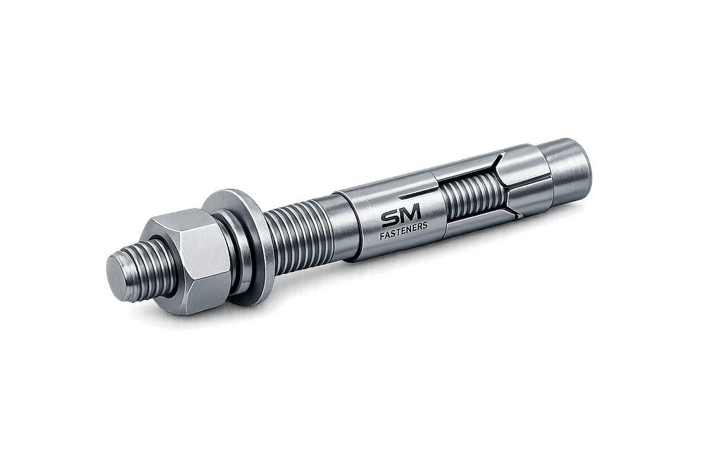
Unlike conventional threaded fasteners that clamp two metallic components, expansion bolts function as structural anchoring devices, converting tightening torque into radial expansion forces that develop frictional and mechanical interlock within a base material.
They are extensively specified in:
- Structural steel erection
- Petrochemical plant installations
- Equipment foundation anchoring
- Offshore modules
- Power generation facilities
- LNG terminals
- Infrastructure and transportation systems
Modern EPC specifications increasingly require expansion anchors capable of:
- Predictable preload generation
- Verified pull-out capacity
- Seismic resistance
- Corrosion durability
- Traceable manufacturing compliance
Within industrial procurement environments, expansion bolts are categorized as safety-critical fastening components because anchorage failure directly compromises structural integrity or equipment stability.
1.1 Role of Expansion Bolts in Engineered Assemblies
Expansion bolts provide the mechanical interface between:
| Structural Element | Anchored Component |
|---|---|
| Reinforced concrete | Structural steel columns |
| RCC foundation | Rotating machinery |
| Masonry wall | Pipe supports |
| Tunnel lining | Rail infrastructure systems |
| Offshore deck | Process equipment skids |
They enable installation after concrete curing, eliminating dependency on cast-in anchor positioning tolerances.
1.2 Industrial Procurement Classification
Expansion bolts are typically specified under:
- ISO Fastening Systems
- DIN Mechanical Anchors
- ASTM Structural Fasteners
- BS Anchorage Systems
Procurement teams evaluate based on:
- Load rating certification
- Material traceability
- Installation reliability
- Corrosion resistance lifecycle
- Compliance documentation
As an ISO 9001, MSME, and UKAF-certified manufacturer, SM Fasteners integrates expansion bolts within controlled manufacturing systems aligned to global EPC project requirements.
2. Technical Definition
2.1 Engineering Definition
An Expansion Bolt is a mechanical anchoring fastener consisting of a threaded bolt or stud combined with an expandable sleeve or wedge mechanism that generates radial pressure against the base material when tightened.
Functional Principle
Tightening torque → axial movement → expansion element activation → radial compressive force → friction + mechanical interlock → load transfer.
2.2 Major Components
| Component | Function |
|---|---|
| Threaded Bolt / Stud | Applies tensile force |
| Expansion Sleeve | Produces radial pressure |
| Cone / Wedge | Drives expansion |
| Washer | Load distribution |
| Nut / Head | Torque application interface |
2.3 Anchor Load Transfer Mechanisms
Expansion bolts resist loads through combined mechanisms:
- Frictional Resistance
- Bearing Stress
- Mechanical Interlock
- Concrete Confinement Pressure
Unlike adhesive anchors, expansion anchors develop instant load capacity after installation.
2.4 Anchor Categories (Engineering Classification)
| Category | Mechanism |
|---|---|
| Torque-Controlled Expansion Anchor | Sleeve expands via tightening torque |
| Wedge Anchor | Cone pulled into clip for expansion |
| Shield Anchor | Multi-segment expansion sleeve |
| Sleeve Anchor Anchor Bolt | Full-length expansion |
| Through Bolt Anchor | Pre-assembled installation type |
3. Load Mechanics & Force Behavior
3.1 Fundamental Load Types
Expansion bolts must resist combined loading conditions:
| Load Type | Description |
|---|---|
| Tensile Load | Pull-out force perpendicular to surface |
| Shear Load | Parallel sliding force |
| Combined Load | Simultaneous tension & shear |
| Dynamic Load | Vibrating equipment |
| Seismic Load | Reversal cyclic loading |
3.2 Expansion Force Development
When torque is applied:
Where:
- T = Applied torque
- Fₚ = Bolt preload (axial force)
- Fᵣ = Radial expansion force
Radial pressure increases friction coefficient between anchor sleeve and concrete wall.
3.3 Torque–Tension Relationship
Preload generated:
Where:
| Symbol | Meaning |
|---|---|
| F | Preload force |
| T | Applied torque |
| K | Nut factor |
| D | Nominal diameter |
Typical nut factor:
| Condition | K Value |
|---|---|
| Dry | 0.20–0.25 |
| Zinc plated | 0.18–0.22 |
| Lubricated | 0.14–0.18 |
3.4 Expansion Mechanics in Concrete
The expansion mechanism creates:
- Compressive hoop stress in concrete
- Contact pressure at sleeve interface
- Frictional resistance proportional to preload
Key governing factors:
- Embedment depth
- Hole diameter tolerance
- Concrete strength class
- Edge distance
- Spacing between anchors
3.5 Failure Modes (Engineering Perspective)
3.5.1 Anchor Pull-Out
Occurs when friction capacity is insufficient.
Influenced by:
- Low embedment depth
- Weak concrete
- Incorrect torque
3.5.2 Concrete Cone Failure
Formation of a conical fracture zone.
Governed by:
- Edge distance
- Anchor spacing
- Concrete tensile strength
3.5.3 Steel Failure
Bolt tensile rupture.
Occurs when:
3.5.4 Shear Failure
Common in structural base plates.
Mitigation:
- Increased diameter
- Higher property class
- Shear lugs or plates
3.5.5 Slip Failure
Loss of preload due to vibration.
Typical causes:
- Poor installation torque
- Surface contamination
- Insufficient expansion pressure
3.5.6 Hydrogen Embrittlement Risk
Applicable to:
- High-strength anchors (>1000 MPa)
- Electroplated coatings
Control methods implemented by SM Fasteners:
- Controlled plating processes
- Post-bake treatment
- Hardness monitoring
4. Joint Design Principles
4.1 Anchor Design Philosophy
Expansion bolts transform a concrete substrate into a load-bearing threaded interface.
Design must ensure:
- Concrete strength > anchor demand
- Proper embedment
- Controlled preload
- Load redistribution safety
4.2 Critical Design Parameters
| Parameter | Engineering Impact |
|---|---|
| Embedment Depth | Primary load capacity driver |
| Edge Distance | Prevents concrete breakout |
| Anchor Spacing | Avoids stress overlap |
| Hole Diameter | Controls expansion efficiency |
| Installation Torque | Determines preload |
4.3 Minimum Edge Distance Guidelines
| Diameter | Minimum Edge Distance |
|---|---|
| M8 | 50 mm |
| M10 | 60 mm |
| M12 | 75 mm |
| M16 | 90 mm |
| M20 | 120 mm |
| M24 | 150 mm |
4.4 Embedment Depth Logic
Recommended embedment:
Where:
- = effective embedment depth
- = anchor diameter
Deeper embedment improves tensile capacity but increases drilling requirement.
4.5 Concrete Interaction Behavior
Concrete resists expansion through:
- Radial compression
- Aggregate interlock
- Confinement effect
High-strength concrete (>C40) provides higher pull-out resistance but requires precise hole tolerance control.
4.6 Preload Design Objective
Expansion bolts must operate within:
Ensures:
- Maximum friction
- No yielding
- Long fatigue life
4.7 Fatigue Performance Considerations
Critical in:
- Turbines
- Compressors
- Rail infrastructure
- Rotating machinery
Design recommendations:
- Maintain preload > external fluctuating load
- Avoid cyclic slip
- Use hardened washers
- Apply calibrated torque installation
4.8 Seismic & Dynamic Design
Seismic applications require:
- Ductile steel grades
- Verified displacement capacity
- Controlled expansion force
- Certified testing protocols
Expansion anchors must sustain cyclic tension without loss of engagement.
4.9 Temperature Effects
Material expansion mismatch influences preload retention.
| Temperature Range | Design Consideration |
|---|---|
| −50°C | Impact toughness |
| 200°C | Strength reduction begins |
| 400°C | Carbon steel degradation |
| 600°C | Alloy steel preferred |
| Cryogenic | Austenitic stainless required |
Advanced alloy and nickel-based expansion bolts supplied by SM Fasteners address high-temperature and corrosive environments.
4.10 Engineering Selection Workflow
- Define load condition
- Determine substrate strength
- Select anchor type
- Choose material grade
- Verify embedment depth
- Calculate preload
- Confirm corrosion protection
- Validate installation torque
- Ensure certification availability
5. Expansion Bolt Product Types & Variants
Expansion bolt selection is fundamentally driven by load direction, substrate behavior, installation access, and long-term environmental exposure.
Industrial projects rarely specify a generic anchor; instead, the anchor geometry is engineered for predictable expansion performance.
5.1 Torque-Controlled Sleeve Expansion Bolts
Functional Description
A cylindrical sleeve expands along its full length when tightening force pulls a cone into the sleeve.
Characteristics
- Uniform radial pressure distribution
- Suitable for cracked concrete
- Reduced localized stress concentration
- Controlled installation torque
Typical Uses
- Pipe supports
- Cable trays
- HVAC systems
- Light-to-medium structural fixtures
5.2 Wedge Expansion Anchors
Working Principle
A conical wedge is drawn into a clip or expansion collar at the embedded end.
Engineering Advantages
- High tensile load capacity
- Immediate full load capability
- Reliable for heavy equipment anchoring
Applications
- Structural steel base plates
- Heavy machinery foundations
- Offshore skid mounting
- Petrochemical structures
5.3 Shield Anchors (Heavy-Duty Expansion Bolts)
Multi-segment expansion sleeves generate strong mechanical interlock.
Features
- High pull-out resistance
- Excellent performance in masonry
- Effective in variable substrate density
Commonly used for:
- Infrastructure projects
- Tunnel systems
- Rail installations
5.4 Through Bolt Expansion Anchors
Preassembled anchor inserted through fixture into drilled hole.
Advantages:
- Fast installation
- Reduced alignment error
- Suitable for repetitive installations
Preferred in EPC construction environments where installation speed impacts project schedules.
5.5 Stud-Type Expansion Anchors
Headless threaded studs allowing external nut installation.
Benefits:
- Adjustable fixture positioning
- High tensile performance
- Easy replacement
5.6 Internal Thread Expansion Anchors
Provide a female threaded interface inside concrete.
Used where:
- Equipment removal required
- Flush mounting needed
- Reusable anchoring desired
5.7 Heavy-Duty Structural Expansion Bolts
Designed for:
- Seismic zones
- Dynamic machinery
- Offshore environments
Manufactured using alloy steels, duplex stainless, and nickel alloys available through SM Fasteners for aggressive industrial conditions.
6. Dimensional Logic & Anchor Geometry
6.1 Engineering Geometry Principles
Expansion bolt dimensions directly influence:
- Load capacity
- Expansion pressure
- Concrete stress distribution
- Fatigue life
Primary geometric variables:
| Parameter | Symbol | Function |
|---|---|---|
| Nominal Diameter | D | Load capacity driver |
| Effective Embedment | hef | Pull-out resistance |
| Expansion Length | Le | Radial force distribution |
| Thread Length | Lt | Clamp engagement |
| Hole Diameter | dh | Expansion efficiency |
6.2 Standard Expansion Bolt Dimensional Table
Table — Metric Expansion Bolt Dimensions
| Size | Thread Pitch | Hole Dia (mm) | Embedment (mm) | Overall Length (mm) | Washer OD (mm) | Nut Size |
|—|—|—|—|—|—|
| M8 | 1.25 | 8 | 40 | 60–80 | 16 | 13 mm |
| M10 | 1.5 | 10 | 50 | 75–100 | 20 | 17 mm |
| M12 | 1.75 | 12 | 60 | 90–120 | 24 | 19 mm |
| M16 | 2.0 | 16 | 80 | 110–160 | 30 | 24 mm |
| M20 | 2.5 | 20 | 100 | 140–200 | 37 | 30 mm |
| M24 | 3.0 | 24 | 120 | 180–260 | 44 | 36 mm |
| M30 | 3.5 | 30 | 150 | 220–320 | 56 | 46 mm |
Dimensional systems manufactured at SM Fasteners follow controlled tolerance machining aligned with ISO metric standards.
6.3 Geometry Influence on Load Performance
Increasing Diameter
✔ Higher tensile capacity
✔ Greater shear resistance
✔ Increased drilling requirement
Increasing Embedment Depth
✔ Improved pull-out strength
✔ Higher safety margin
✔ Reduced concrete cone failure risk
6.4 Recommended Hole Tolerance
| Diameter | Hole Tolerance |
|---|---|
| ≤ M12 | +0.3 mm |
| M16–M24 | +0.4 mm |
| ≥ M30 | +0.5 mm |
Oversized holes reduce expansion efficiency and preload retention.
6.5 Fixture Thickness Selection
Where:
- L = bolt length
7. Thread Systems & Tolerance Engineering
Expansion bolts interface with global threaded assemblies requiring interchangeability.
7.1 Thread Standard Comparison Table
| Thread System | Standard | Application Region |
|---|---|---|
| Metric Coarse | ISO 261 / ISO 965 | Global |
| Metric Fine | ISO 261 | Precision assemblies |
| UNC | ASME B1.1 | USA |
| UNF | ASME B1.1 | High preload |
| BSW | BS 84 | Legacy UK |
| BSF | BS 84 | Fine pitch UK |
7.2 Thread Tolerance Classes
| Class | Fit Type | Use |
|---|---|---|
| 6g | Standard external | Structural anchors |
| 6H | Standard internal | Nuts |
| 4h | Close tolerance | High precision |
| 8g | Loose fit | Corrosive environments |
Thread rolling processes used by SM Fasteners improve fatigue resistance through grain flow continuity.
8. Applicable International Standards
Expansion bolts must comply with multi-standard project specifications.
8.1 ISO Standards
| Standard | Scope |
|---|---|
| ISO 898-1 | Mechanical properties of carbon steel fasteners |
| ISO 3506 | Stainless steel mechanical properties |
| ISO 965 | Thread tolerances |
| ISO 4014/4017 | Hex bolts geometry |
| ISO 9001 | Quality management system |
8.2 DIN Standards
| DIN Standard | Description |
|---|---|
| DIN 529 | Expansion anchors |
| DIN 125 | Washers |
| DIN 934 | Hex nuts |
| DIN EN 1992-4 | Anchor design in concrete |
8.3 ASTM Standards
| ASTM Standard | Application |
|---|---|
| ASTM A307 | General purpose bolts |
| ASTM F1554 | Anchor bolts |
| ASTM A193 | High temperature service |
| ASTM A320 | Low temperature service |
| ASTM B633 | Zinc plating |
8.4 British Standards
| BS Standard | Scope |
|---|---|
| BS 5080 | Anchor systems |
| BS EN 14399 | Structural bolting |
| BS 4190 | Metric bolt dimensions |
8.5 Property Class Systems
| Property Class | Yield (MPa) | Tensile (MPa) | Typical Use |
|—|—|—|
| 4.6 | 240 | 400 | Light anchoring |
| 5.8 | 400 | 500 | Medium duty |
| 8.8 | 640 | 800 | Structural |
| 10.9 | 900 | 1000 | Heavy machinery |
| 12.9 | 1080 | 1200 | High-strength |
9. Interchangeability & Global Procurement Considerations
9.1 EPC Procurement Requirements
Expansion bolts must provide:
- Cross-standard compatibility
- Repeatable mechanical performance
- Verified traceability
- Dimensional interchangeability
9.2 Engineering Interchangeability Rules
| Parameter | Must Match |
|---|---|
| Thread form | Mandatory |
| Pitch | Mandatory |
| Strength class | Mandatory |
| Embedment depth | Critical |
| Washer diameter | Recommended |
Failure to maintain equivalency can cause preload loss or structural failure.
9.3 Project Documentation Alignment
Global EPC buyers require:
- ISO certification
- MTC traceability
- Heat numbers
- Inspection records
- Dimensional verification
Manufacturing and documentation practices at SM Fasteners integrate these requirements into production workflow.
10. Engineering Selection Matrix — Expansion Bolt Type vs Application
| Application | Recommended Type | Reason |
|---|---|---|
| Structural columns | Wedge anchor | High tensile capacity |
| Machinery foundations | Heavy-duty expansion | Vibration resistance |
| Pipe racks | Sleeve anchor | Even load distribution |
| Offshore modules | Alloy expansion anchor | Corrosion resistance |
| Chemical plants | Stainless expansion anchor | Chemical resistance |
| Rail infrastructure | Shield anchor | Masonry compatibility |
11. Material Grades & Engineering Selection Criteria
Material selection is the single most critical engineering decision governing expansion bolt performance.
Unlike conventional bolts, expansion anchors operate under combined tensile, shear, compressive, and frictional stresses while simultaneously interacting with concrete chemistry and environmental exposure.
Engineering selection must balance:
- Mechanical strength
- Ductility
- Corrosion resistance
- Hydrogen embrittlement risk
- Temperature capability
- Lifecycle cost
11.1 Industrial Material Categories
Expansion bolts manufactured by SM Fasteners cover the full industrial alloy spectrum required for EPC and infrastructure projects.
| Material Category | Typical Grades | Primary Application |
|---|---|---|
| Carbon Steel | C35, C45 | Construction anchoring |
| Alloy Steel | 4140, 4340 | Heavy equipment |
| Stainless Steel | A2-70, A4-80 | Marine & chemical |
| Duplex Stainless | 2205 | Offshore structures |
| Super Duplex | 2507 | Seawater exposure |
| Nickel Alloys | Inconel, Monel | Extreme corrosion |
| SMO 254 | High Mo stainless | Chloride environments |
| PEEK Polymer | Engineering thermoplastic | Electrical isolation |
11.2 Mechanical Properties by Material Grade
Table — Mechanical Properties
| Material | Yield Strength (MPa) | UTS (MPa) | Hardness | Temp Limit |
|---|---|---|---|---|
| CS Grade 4.6 | 240 | 400 | 120 HB | 300°C |
| CS Grade 8.8 | 640 | 800 | 22–32 HRC | 425°C |
| Alloy 10.9 | 900 | 1040 | 32–39 HRC | 450°C |
| Alloy 12.9 | 1080 | 1220 | 39–44 HRC | 450°C |
| SS A2-70 | 450 | 700 | 210 HV | 800°C |
| SS A4-80 | 600 | 800 | 250 HV | 800°C |
| Duplex 2205 | 550 | 800 | 260 HV | 300°C |
| Super Duplex 2507 | 650 | 950 | 300 HV | 300°C |
| Inconel 625 | 480 | 860 | — | 1000°C |
| PEEK | — | — | — | 260°C |
11.3 Material Selection Matrix
| Environment | Recommended Material |
|---|---|
| Indoor structural | Carbon steel 5.8 / 8.8 |
| Heavy machinery | Alloy steel 10.9 |
| Marine atmosphere | A4 stainless |
| Offshore splash zone | Duplex 2205 |
| Seawater immersion | Super Duplex |
| Chemical plants | SMO 254 / Hastelloy |
| Cryogenic LNG | Austenitic stainless |
| Electrical insulation | PEEK anchors |
11.4 Corrosion Resistance vs Environment
Table — Environmental Compatibility
| Environment | CS | SS304 | SS316 | Duplex | Nickel Alloy |
|---|---|---|---|---|---|
| Atmospheric | Good | Excellent | Excellent | Excellent | Excellent |
| Coastal | Poor | Moderate | Good | Excellent | Excellent |
| Seawater | Fail | Moderate | Good | Excellent | Excellent |
| Acidic | Poor | Moderate | Good | Excellent | Excellent |
| H₂S (Sour Service) | Limited | Acceptable | Good | Excellent | Excellent |
| Chlorides | Poor | Moderate | Good | Excellent | Excellent |
Materials supplied for oil & gas service comply with NACE MR0175 / ISO 15156 hardness restrictions when required.
11.5 Temperature Capability Engineering
| Temperature Range | Preferred Material |
|---|---|
| −196°C (LNG) | SS304/316 |
| −50°C | A320 grades |
| 200–400°C | Alloy Steel |
| 400–600°C | Incoloy |
| >800°C | Inconel alloys |
12. Heat Treatment Processes
Heat treatment directly governs strength, fatigue life, and hydrogen embrittlement susceptibility.
12.1 Typical Heat Treatment Route
- Austenitizing
- Quenching
- Tempering
- Stress relieving
12.2 Heat Treatment by Property Class
| Property Class | Process |
|---|---|
| 5.8 | Normalizing |
| 8.8 | Quench & Temper |
| 10.9 | Controlled Q&T |
| 12.9 | High precision tempering |
12.3 Mechanical Impact of Heat Treatment
| Treatment | Result |
|---|---|
| Quenching | High hardness |
| Tempering | Toughness recovery |
| Stress Relief | Reduced distortion |
| Solution Annealing | Stainless corrosion resistance |
12.4 Hardness Limits (Sour Service Requirement)
Per NACE compliance:
| Material | Max Hardness |
|---|---|
| Carbon Steel | 22 HRC |
| Alloy Steel | 26 HRC |
| Stainless Steel | Controlled cold work |
These limits prevent sulfide stress cracking in H₂S environments.
13. End-to-End Manufacturing Workflow
Expansion bolts require controlled manufacturing because anchor reliability depends on dimensional accuracy and metallurgical integrity.
13.1 Raw Material Verification
Incoming inspection includes:
- Mill Test Certificates (EN 10204 3.1)
- Chemical composition verification
- Ultrasonic bar inspection
- PMI testing (XRF/OES)
All raw materials used by SM Fasteners are heat-number traceable.
13.2 Forging vs Machining
| Process | Advantages |
|---|---|
| Hot Forging | Grain flow strength |
| Cold Forging | Dimensional precision |
| CNC Machining | Custom geometries |
Forged expansion cones provide superior fatigue resistance.
13.3 Thread Manufacturing Methods
Thread Rolling (Preferred)
Benefits:
- Increased fatigue strength
- Work hardening
- Continuous grain structure
- Superior surface finish
Thread Cutting
Used for:
- Large diameters
- Exotic alloys
- Custom PEEK fasteners
13.4 Expansion Sleeve Manufacturing
Critical operations:
- Precision slit forming
- Controlled spring elasticity
- Hardness matching with cone
Improper sleeve hardness causes installation failure or inadequate expansion.
13.5 Assembly Process
- Component cleaning
- Sleeve positioning
- Cone insertion
- Washer & nut assembly
- Torque validation sampling
13.6 Traceability System
Each batch includes:
- Heat number
- Manufacturing lot
- Operator record
- Inspection history
Integrated into ISO 9001 quality systems.
14. Surface Finishing & Coating Engineering
Expansion bolts operate in highly corrosive environments where coating selection significantly impacts service life.
14.1 Surface Finish Comparison
Table — Coating Performance
| Coating | Thickness | Corrosion Resistance | Temp Limit | Application |
|---|---|---|---|---|
| Zinc Plated | 5–12 µm | Moderate | 120°C | Indoor |
| Hot Dip Galvanized | 45–85 µm | High | 200°C | Structural |
| Mechanical Galv. | 40 µm | High | 200°C | Hydrogen-safe |
| Dacromet | 8–12 µm | Very High | 300°C | Automotive |
| Geomet | 10–15 µm | Very High | 300°C | Offshore |
| PTFE Coated | Variable | Chemical resistant | 260°C | Chemical plants |
| Black Oxide | Minimal | Low | 150°C | Indoor machinery |
| Passivation | — | Stainless protection | High | Marine |
14.2 Coating Selection by Environment
| Environment | Recommended Finish |
|---|---|
| Indoor dry | Zinc plating |
| Outdoor structural | HDG |
| Marine | Duplex stainless |
| Chemical plant | PTFE |
| Offshore platform | Geomet / Duplex |
| H₂S service | Mechanical galvanizing |
14.3 Hydrogen Embrittlement Control
Critical for property classes ≥10.9.
Preventive measures:
- Non-acid cleaning
- Mechanical plating preferred
- Post plating bake (200°C / 4 hrs)
- Hardness monitoring
14.4 Surface Friction & Torque Relationship
Coatings change nut factor:
| Surface Condition | Nut Factor (K) |
|---|---|
| Dry steel | 0.22 |
| Zinc plated | 0.20 |
| Lubricated | 0.16 |
| PTFE coated | 0.12 |
Torque charts must always reflect coating condition.
14.5 Surface Preparation Steps
- Degreasing
- Shot blasting
- Pickling (controlled)
- Coating application
- Thickness verification
- Adhesion testing
14.6 PEEK Expansion Fastener Surface Advantages
PEEK fasteners supplied by SM Fasteners provide:
- Zero corrosion
- Electrical insulation
- Chemical inertness
- Non-magnetic performance
- Lightweight anchoring
Used in semiconductor, electrical, and clean-room installations.
15. Inspection & Quality Control Systems
Expansion bolts are categorized as safety-critical anchoring components.
Failure risks include structural collapse, equipment instability, vibration amplification, and foundation damage. Therefore, inspection procedures must comply with internationally recognized QA/QC frameworks.
The manufacturing and inspection philosophy implemented by SM Fasteners integrates ISO 9001 quality systems with EPC procurement expectations.
15.1 Quality Assurance Framework
Quality control operates across five stages:
| Stage | Inspection Activity |
|---|---|
| Incoming Material | Chemical & mechanical verification |
| In-Process | Dimensional & hardness control |
| Heat Treatment | Mechanical validation |
| Final Inspection | Functional verification |
| Pre-Shipment | Documentation audit |
15.2 Dimensional Inspection
Critical parameters verified:
- Thread pitch accuracy
- Major/minor diameter
- Sleeve expansion tolerance
- Cone geometry
- Washer dimensions
- Effective embedment length
Measurement equipment:
- Digital micrometers
- Thread gauges (GO/NO-GO)
- Optical comparators
- Coordinate Measuring Machines (CMM)
15.3 Mechanical Testing
Mandatory Tests
| Test | Purpose |
|---|---|
| Proof Load Test | Confirms elastic limit |
| Tensile Test | Determines ultimate strength |
| Hardness Test | Heat treatment validation |
| Wedge Expansion Test | Functional anchor verification |
| Pull-Out Test | Concrete performance validation |
| Shear Test | Structural resistance |
15.4 Non-Destructive Testing (NDT)
Applied to critical industrial projects:
| Method | Detection Capability |
|---|---|
| Magnetic Particle | Surface cracks |
| Ultrasonic Testing | Internal flaws |
| Dye Penetrant | Surface discontinuities |
| Eddy Current | Material defects |
15.5 Positive Material Identification (PMI)
Required for alloy, duplex, and nickel materials.
Methods:
- XRF Analysis
- Optical Emission Spectroscopy
Ensures compliance with project metallurgy specifications.
15.6 Certification & Documentation
Typical export documentation:
- EN 10204 3.1 Material Test Certificate
- 3.2 Certification (Third-Party Witness)
- Heat Treatment Reports
- Dimensional Inspection Reports
- Coating Thickness Records
- Hardness Certificates
- Certificate of Conformity (CoC)
16. Engineering Applications Across Industries
Expansion bolts serve as primary anchoring elements across global industrial sectors.
16.1 Construction & Structural Steel
Applications:
- Column base plates
- Façade systems
- Steel mezzanines
- Stadium structures
Design drivers:
- High shear resistance
- Fatigue durability
- Rapid installation
16.2 Oil & Gas Industry
Upstream
- Rig structures
- Pump skids
- Wellhead equipment
Midstream
- Pipe supports
- Compressor stations
Downstream
- Refinery structures
- Reactor foundations
Requirements:
- NACE compliance
- Corrosion resistance
- Traceability
16.3 Power Generation
Used in:
- Turbine anchoring
- Generator bases
- Cable tray systems
- Nuclear auxiliary structures
High preload retention is essential for vibration resistance.
16.4 Petrochemical & Chemical Processing
Challenges:
- Acid exposure
- Thermal cycling
- Chloride corrosion
Recommended materials:
- A4 stainless
- SMO 254
- Nickel alloys
16.5 LNG & Offshore Platforms
Environmental demands:
- Seawater immersion
- Cyclic loading
- Extreme corrosion
Preferred solutions:
- Duplex / Super Duplex anchors
- PTFE-coated systems
- Nickel alloy expansion bolts
16.6 Railways & Infrastructure
Applications include:
- Rail fixing supports
- Bridge components
- Tunnel installations
- Metro systems
Shield expansion anchors are commonly specified.
16.7 Automotive & Heavy Equipment
Used for:
- Assembly lines
- Robotic base anchoring
- Dynamic machine installation
Critical requirement: vibration resistance.
16.8 Shipbuilding
Expansion bolts secure:
- Deck equipment
- Pipe brackets
- Navigation systems
Marine-grade stainless fasteners required.
16.9 PEEK Fastener Applications
PEEK expansion fasteners supplied by SM Fasteners are used where metallic anchors are unsuitable:
- Semiconductor manufacturing
- Electrical panels
- MRI environments
- Chemical dosing systems
- Clean-room installations
17. Export Capability & Global Supply Readiness
17.1 Industrial Packaging Systems
| Packaging Method | Purpose |
|---|---|
| VCI Packaging | Corrosion protection |
| Thread Caps | Thread damage prevention |
| Oil Coating | Transit protection |
| Vacuum Packing | Marine shipment |
| Heat-Sealed Bags | Moisture control |
17.2 Export Crating
- ISPM-15 compliant wooden crates
- Shock-resistant palletization
- Container load optimization
- Barcode traceability
17.3 Documentation Package
Each shipment may include:
- Packing List
- Commercial Invoice
- Certificate of Origin
- MTC (EN 10204 3.1 / 3.2)
- Inspection Release Note
- Third-Party Inspection (TPI) approval
17.4 Global EPC Supply Integration
SM Fasteners supports:
- Project bulk orders
- Custom anchor engineering
- Special alloys manufacturing
- Emergency shutdown supply
- Long-term framework agreements
18. Engineering Tables
18.1 Proof Load & Tensile Strength Table
| Size | Grade | Proof Load (kN) | Tensile Strength (kN) |
|---|---|---|---|
| M8 | 8.8 | 14 | 20 |
| M10 | 8.8 | 22 | 32 |
| M12 | 8.8 | 32 | 46 |
| M16 | 8.8 | 58 | 84 |
| M20 | 8.8 | 90 | 130 |
| M24 | 8.8 | 130 | 188 |
18.2 Mechanical Properties by Property Class
| Class | Yield (MPa) | Tensile (MPa) | Elongation |
|---|---|---|---|
| 5.8 | 400 | 500 | 12% |
| 8.8 | 640 | 800 | 12% |
| 10.9 | 900 | 1040 | 9% |
| 12.9 | 1080 | 1220 | 8% |
18.3 Tightening Torque Chart
(Zinc plated condition)
| Size | Grade 8.8 Torque (Nm) | Grade 10.9 Torque (Nm) |
|---|---|---|
| M8 | 25 | 36 |
| M10 | 49 | 72 |
| M12 | 85 | 125 |
| M16 | 210 | 310 |
| M20 | 410 | 600 |
| M24 | 710 | 1020 |
18.4 Preload Calculation (Worked Example)
Formula:
Example:
- Bolt: M16
- Torque = 210 Nm
- Nut Factor K = 0.20
- Diameter = 0.016 m
Result: Expected clamping force ≈ 65 kN.
18.5 Surface Finish Performance Comparison
| Finish | Corrosion Life | Maintenance |
|---|---|---|
| Zinc Plated | Low–Medium | Periodic |
| HDG | High | Low |
| Dacromet | Very High | Minimal |
| PTFE | Chemical Resistant | Minimal |
| Stainless | Excellent | None |
18.6 Thread Standards & Tolerances
| Thread | Pitch System | Tolerance |
|---|---|---|
| Metric | ISO | 6g/6H |
| UNC | Unified | 2A/2B |
| UNF | Unified Fine | 2A/2B |
| BSW | British | Medium |
| BSF | British Fine | Close |
18.7 Expansion Bolt Weight Chart
(Typical engineering reference — aligned with SM Fasteners manufacturing data)
| Size | Approx Weight / Piece | Weight / 100 pcs |
|---|---|---|
| M8×75 | 0.045 kg | 4.5 kg |
| M10×100 | 0.075 kg | 7.5 kg |
| M12×120 | 0.12 kg | 12 kg |
| M16×150 | 0.24 kg | 24 kg |
| M20×200 | 0.46 kg | 46 kg |
| M24×250 | 0.82 kg | 82 kg |
19. Failure Prevention & Engineering Best Practices
Installation Controls
- Clean drilled hole thoroughly
- Use calibrated torque wrench
- Avoid over-torque expansion
- Maintain minimum edge distance
- Follow specified embedment depth
Design Controls
- Maintain preload above service load
- Prevent cyclic slip
- Select coating for lifecycle exposure
- Verify compatibility with concrete strength
20. SM Fasteners — Engineering Manufacturing Capability
Through ISO 9001-controlled manufacturing, MSME recognition, and UKAF-aligned certification systems, SM Fasteners delivers expansion bolts engineered for:
- Global EPC projects
- Heavy engineering installations
- Offshore and LNG facilities
- Chemical processing environments
- Infrastructure megaprojects
Capabilities include:
- Custom expansion anchor engineering
- Exotic alloy manufacturing
- Precision thread rolling
- Controlled heat treatment
- Full inspection traceability
- Export-ready packaging systems