

Sleeve Anchor Bolt
1. Industry Context
1.1 Role of Mechanical Anchoring Systems in Modern Engineering
Mechanical anchoring systems form the structural interface between equipment, structural members, and base substrates. In heavy engineering environments, the anchorage system must safely transfer loads from installed components into concrete, masonry, or structural foundations without inducing failure mechanisms such as cracking, pull-out, or shear rupture.

Among mechanical anchors, the Sleeve Anchor Bolt represents one of the most versatile and globally accepted fastening solutions for:
- Structural steel installation
- Equipment base fixing
- Pipe supports
- Cable trays
- Mechanical skids
- Industrial machinery anchoring
- Infrastructure retrofits
Unlike cast-in anchors requiring early placement, sleeve anchors enable post-installed anchorage, allowing flexibility during construction sequencing and maintenance upgrades.
1.2 Industrial Demand Drivers
Construction & Infrastructure
- Structural connections to reinforced concrete
- Seismic retrofit installations
- Rail and bridge component anchoring
Oil & Gas Sector
- Pipe rack supports
- Instrument stands
- Secondary steel structures
- Maintenance platforms
Power Generation
- Turbine auxiliary equipment mounting
- Electrical panel supports
- Cable containment systems
Petrochemical & Process Plants
- Corrosion-resistant anchoring systems
- Vibration-resistant equipment installations
LNG & Offshore Installations
- Stainless and duplex material sleeve anchors resist chloride attack and cyclic loading.
Heavy Equipment & OEM Manufacturing
- Modular skid anchoring
- Machine foundation fixation
SM Fasteners supplies sleeve anchor bolts engineered for high-integrity industrial applications, aligned with global EPC procurement standards and supported by ISO 9001 certified quality systems.
1.3 Position Within Fastener Engineering
Sleeve anchor bolts fall under:
Category: Mechanical Expansion Anchors
Load Transfer Principle: Radial expansion friction + mechanical interlock
They bridge the gap between:
| Fastener Type | Installation | Load Capacity | Removability |
|---|---|---|---|
| Cast-in Anchor | Pre-concrete | Very High | Permanent |
| Chemical Anchor | Post-installed | Very High | Semi-permanent |
| Sleeve Anchor | Post-installed | Medium–High | Removable |
| Screw Anchor | Post-installed | Medium | Removable |
2. Technical Definition
2.1 What is a Sleeve Anchor Bolt?
A Sleeve Anchor Bolt is a torque-controlled mechanical anchor consisting of:
- Threaded bolt or stud
- Expansion sleeve
- Cone or expander element
- Nut
- Washer
When tightened, axial tension pulls the cone into the sleeve, expanding it outward against the hole wall, generating anchoring force.
2.2 Functional Principle
Installation sequence:
- Hole drilled into base material
- Anchor inserted through fixture
- Nut tightened
- Cone advances into sleeve
- Sleeve expands radially
- Frictional resistance develops
- Load transfer achieved
2.3 Load Transfer Mechanism
The sleeve anchor operates through combined mechanisms:
1. Frictional Resistance
Radial expansion pressure produces friction between sleeve and concrete.
2. Mechanical Interlock
Surface irregularities of concrete provide additional holding power.
3. Compression Zone Formation
Localized compressive stresses distribute loads into substrate.
2.4 Primary Components
| Component | Function | Engineering Requirement |
|---|---|---|
| Bolt/Stud | Applies tensile force | High strength, rolled threads |
| Expansion Sleeve | Transfers load | Controlled ductility |
| Cone | Expansion actuator | Hardened surface |
| Washer | Load distribution | Prevent embedment |
| Nut | Torque application | Compatible thread class |
SM Fasteners manufactures precision-machined expansion assemblies ensuring consistent expansion geometry and predictable load behavior.
3. Load Mechanics & Force Behavior
3.1 Fundamental Load Types
Sleeve anchors must resist multiple simultaneous forces.
Tensile Load (Pull-Out)
Force acting perpendicular to surface.
Failure modes:
- Concrete cone failure
- Pull-out failure
- Steel fracture
Shear Load
Force parallel to mounting surface.
Failure modes:
- Bolt shear fracture
- Edge breakout
- Concrete crushing
Combined Loading
Common in industrial installations.
Examples:
- Pipe supports
- Cable trays
- Rotating equipment
Design must consider interaction formulas.
3.2 Expansion Mechanics
Radial pressure generated:
Where:
- = radial pressure
- = tensile expansion force
- = cone contact area
Proper expansion depends on:
- Sleeve material hardness
- Surface finish
- Hole diameter tolerance
- Installation torque accuracy
3.3 Torque–Tension Relationship
Torque applied during tightening produces preload.
Where:
| Symbol | Meaning |
|---|---|
| F | Preload force |
| T | Applied torque |
| K | Nut factor |
| D | Nominal diameter |
Typical nut factor values:
| Condition | K Value |
|---|---|
| Dry | 0.20–0.25 |
| Zinc plated | 0.18–0.22 |
| Lubricated | 0.14–0.18 |
Controlled torque is critical to avoid:
- Under-expansion
- Concrete damage
- Thread yielding
3.4 Preload Development
Preload generates clamping force securing the fixture.
Key principle:
Joint integrity depends on preload — not bolt strength alone.
Benefits of proper preload:
- Prevents loosening
- Improves fatigue resistance
- Reduces shear loading on bolt
- Maintains vibration stability
3.5 Friction Effects
Approximate torque distribution:
| Energy Use | Percentage |
|---|---|
| Thread friction | 40–50% |
| Bearing surface friction | 40–50% |
| Actual preload | 10–15% |
Hence manufacturing consistency of threads and coatings directly affects anchor performance.
SM Fasteners maintains controlled thread rolling processes to stabilize nut factor variability.
3.6 Embedment Depth Influence
Holding capacity strongly correlates with embedment.
General rule:
Greater embedment provides:
- Larger compression cone
- Higher pull-out resistance
- Improved fatigue life
However excessive embedment increases installation torque and risk of concrete cracking.
3.7 Concrete Interaction Behavior
Sleeve anchors rely on base material integrity.
Suitable Substrates
- Cracked concrete
- Non-cracked concrete
- Solid brick
- Dense stone
Not Recommended
- Low-density block
- Lightweight concrete
- Hollow masonry (unless engineered variant)
3.8 Edge Distance & Spacing Principles
Incorrect spacing causes concrete failure before bolt failure.
| Parameter | Typical Minimum |
|---|---|
| Edge distance | ≥ 5 × diameter |
| Anchor spacing | ≥ 8 × diameter |
| Hole tolerance | +0.1 to +0.2 mm |
3.9 Failure Mechanisms
1. Concrete Cone Failure
Most common tensile failure.
2. Pull-Out Failure
Insufficient expansion force.
3. Steel Failure
Occurs in high-strength anchors.
4. Shear Edge Breakout
Insufficient edge distance.
5. Fatigue Failure
Cyclic loading applications.
6. Stress Corrosion Cracking
Occurs in chloride or H₂S environments.
SM Fasteners material selection includes duplex, super duplex, nickel alloys, and PEEK fasteners for aggressive environments.
4. Joint Design Principles
4.1 Anchor-Based Joint Philosophy
Sleeve anchors convert a concrete foundation into a load-carrying structural member.
Design objectives:
- Maintain compression between joined parts
- Avoid dynamic slip
- Transfer load safely into substrate
4.2 Joint Categories
| Joint Type | Description | Anchor Role |
|---|---|---|
| Structural | Steel columns | Primary load transfer |
| Mechanical | Equipment base | Vibration resistance |
| Electrical | Cable trays | Support load |
| Process | Pipe supports | Thermal movement control |
4.3 Clamping Force Concept
Ideal condition:
If external load exceeds preload:
- Joint separates
- Fatigue increases
- Anchor loosens
4.4 Shear Load Strategy
Recommended engineering practice:
- Friction carries shear load
- Bolt should not act as shear pin
Achieved by:
- Correct torque
- Flat washer usage
- Surface preparation
4.5 Installation Torque Control
Engineering installation requires:
- Calibrated torque wrench
- Verified hole depth
- Debris removal
- Correct washer seating
Improper installation causes >70% of anchor failures globally.
4.6 Vibration Resistance Design
Applications such as turbines or compressors require:
- Higher preload ratios
- Hardened washers
- Controlled friction coefficient
SM Fasteners supplies engineered anchor assemblies validated for vibration-prone installations.
4.7 Thermal Expansion Considerations
Temperature variation introduces additional stresses.
Design checks must consider:
- Differential expansion
- Relaxation loss
- Material creep at elevated temperature
High-temperature materials available:
- Inconel
- Incoloy
- Hastelloy
- SMO 254
- PEEK polymer anchors (non-metallic environments)
4.8 Safety Factors (Typical EPC Practice)
| Load Type | Safety Factor |
|---|---|
| Static tension | 3.0 |
| Static shear | 3.0 |
| Dynamic load | 4.0–5.0 |
| Seismic | Project specific |
4.9 Engineering Selection Parameters
Engineers must evaluate:
- Required load capacity
- Base material strength
- Environment corrosivity
- Temperature range
- Installation accessibility
- Inspection requirements
SM Fasteners provides project-specific engineering support aligned with global EPC procurement workflows.
5. Product Types and Variants
Sleeve anchor bolts are engineered in multiple configurations to accommodate installation conditions, load demands, corrosion environments, and maintenance accessibility requirements encountered in EPC and industrial projects.
SM Fasteners manufactures sleeve anchors using controlled dimensional tolerances ensuring consistent expansion behavior across global installations.
5.1 Classification by Head Configuration
5.1.1 Hex Head Sleeve Anchor
Primary Industrial Variant
Applications:
- Structural steel fixing
- Pipe supports
- Heavy equipment bases
- Infrastructure assemblies
Engineering Advantages:
- High torque transmission
- Easy removal and replacement
- Suitable for thick fixtures
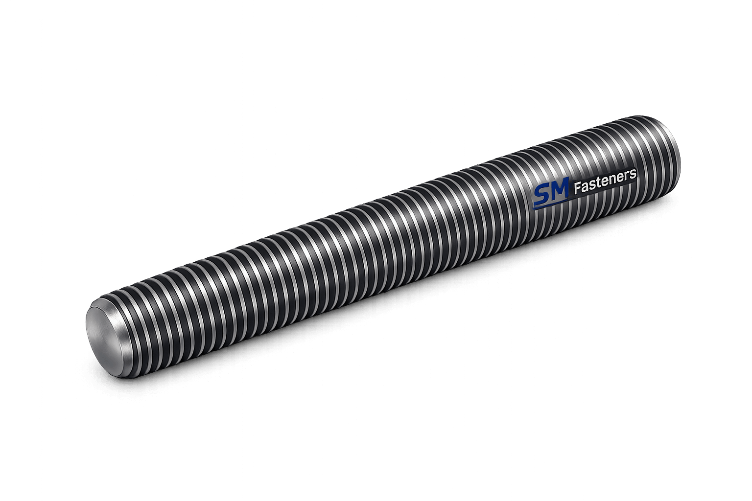
5.1.2 Stud Type Sleeve Anchor Hex Bolt
Configuration:
- Fully Threaded Stud
- Separate nut & washer
Preferred For:
- Adjustable installations
- Alignment-critical assemblies
- Machinery installation
5.1.3 Flat Head (Countersunk) Sleeve Anchor
Applications:
- Architectural panels
- Electrical enclosures
- Flush surface installations
Engineering Characteristic:
- Head sits level with mounting surface
- Reduced snagging risk
5.1.4 Round Head / Dome Head Sleeve Anchor
Used where:
- Aesthetic exposure exists
- Reduced tampering required
5.1.5 Eye Bolt Sleeve Anchor
Used in:
- Cable suspension
- Temporary lifting fixtures
- Maintenance access systems
5.2 Classification by Expansion Geometry
Light-Duty Sleeve Anchors
- Thin sleeve expansion
- Lower torque requirement
- Used for non-structural supports
Medium-Duty Sleeve Anchors
- Balanced expansion length
- General industrial use
Heavy-Duty Sleeve Anchors
- Extended expansion zone
- Increased radial pressure
- High pull-out resistance
5.3 Sleeve Length Variants
| Type | Expansion Length | Engineering Effect |
|---|---|---|
| Short Sleeve | Local expansion | Fast installation |
| Medium Sleeve | Balanced load | General-purpose |
| Full-Length Sleeve | Distributed load | Crack resistance |
5.4 Thread Form Variants
SM Fasteners produces anchors compatible with global project specifications:
- Metric coarse
- Metric fine
- UNC
- UNF
- BSW
- BSF
Thread rolling is preferred for improved fatigue resistance and surface hardness.
6. Dimensional Logic and Geometry
6.1 Fundamental Design Dimensions
Critical dimensions governing performance:
- Nominal diameter
- Sleeve outside diameter
- Embedment depth
- Effective thread length
- Expansion cone angle
- Fixture thickness allowance
6.2 Standard Dimensional Specification Table
Typical Metric Sleeve Anchor Dimensions
| Size | Thread Pitch (mm) | Anchor Length (mm) | Hole Dia (mm) | Embedment (mm) | Hex Size (mm) |
|---|---|---|---|---|---|
| M6 | 1.0 | 45–80 | 6 | 30 | 10 |
| M8 | 1.25 | 60–100 | 8 | 40 | 13 |
| M10 | 1.5 | 75–150 | 10 | 50 | 17 |
| M12 | 1.75 | 90–200 | 12 | 60 | 19 |
| M16 | 2.0 | 110–250 | 16 | 80 | 24 |
| M20 | 2.5 | 140–300 | 20 | 100 | 30 |
| M24 | 3.0 | 180–350 | 24 | 120 | 36 |
Dimensional tolerances follow ISO fastener practice integrated within SM Fasteners’ ISO 9001 quality system.
6.3 Length Selection Logic
Anchor length calculation:
Where:
| Symbol | Meaning |
|---|---|
| | Fixture thickness |
| | Embedment depth |
| Clearance allowance | |
| Washer + nut height |
6.4 Embedment Depth Design Table
| Size | Minimum Embedment | Recommended Embedment |
|---|---|---|
| M6 | 25 mm | 30 mm |
| M8 | 35 mm | 40 mm |
| M10 | 45 mm | 50 mm |
| M12 | 55 mm | 60 mm |
| M16 | 70 mm | 80 mm |
| M20 | 90 mm | 100 mm |
| M24 | 110 mm | 120 mm |
6.5 Expansion Cone Geometry
Typical cone angle:
- 6°–10°
Engineering balance:
- Lower angle → higher holding power
- Higher angle → easier installation
SM Fasteners controls cone machining accuracy to maintain predictable expansion force.
6.6 Installation Clearance Requirements
| Parameter | Requirement |
|---|---|
| Hole tolerance | +0.1 to +0.2 mm |
| Hole depth | Embedment + 10 mm |
| Surface flatness | ≤ 0.5 mm deviation |
| Cleaning | Dust-free mandatory |
7. Applicable International Standards
Sleeve anchor bolts integrate requirements from multiple fastener and anchoring standards.
7.1 ISO Standards
| Standard | Description |
|---|---|
| ISO 898-1 | Mechanical properties of carbon steel bolts |
| ISO 3506 | Stainless steel fasteners |
| ISO 965 | Thread tolerances |
| ISO 4014 | Hex head bolts |
| ISO 7089 | Flat washers |
| ISO 4032 | Hex nuts |
7.2 ASTM Standards
| Standard | Application |
|---|---|
| ASTM F593 | Stainless steel bolts |
| ASTM F594 | Stainless steel nuts |
| ASTM A193 | High-temperature alloy fasteners |
| ASTM A320 | Low-temperature service |
| ASTM B633 | Zinc plating |
| ASTM F606 | Mechanical testing |
7.3 DIN Standards
| DIN Standard | Description |
|---|---|
| DIN 933 | Hex bolts |
| DIN 934 | Hex nuts |
| DIN 125 | Washers |
| DIN 267 | Fastener technical conditions |
7.4 British Standards (BS)
| BS Standard | Scope |
|---|---|
| BS 3692 | Metric precision fasteners |
| BS 1083 | Steel bolts & screws |
| BS EN ISO 898 | Mechanical properties |
7.5 Thread Standards & Tolerances Table
| Thread System | Angle | Typical Class |
|---|---|---|
| Metric ISO | 60° | 6g / 6H |
| UNC | 60° | 2A / 2B |
| UNF | 60° | 2A / 2B |
| BSW | 55° | Medium fit |
| BSF | 55° | Fine fit |
7.6 Property Class System
Carbon Steel Property Classes
| Class | Yield Strength (MPa) | UTS (MPa) |
|---|---|---|
| 5.8 | 400 | 500 |
| 8.8 | 640 | 800 |
| 10.9 | 900 | 1040 |
| 12.9 | 1080 | 1220 |
Stainless Steel Grades (ISO 3506)
| Grade | Strength Level | Typical Use |
|---|---|---|
| A2-70 | General corrosion | Construction |
| A4-70 | Marine | Offshore |
| A4-80 | High strength corrosion | Chemical plants |
7.7 Interchangeability Considerations
Engineering procurement must verify:
- Thread compatibility
- Head dimensions
- Washer bearing area
- Property class equivalence
Example:
- ISO 4014 ≈ DIN 931 ≈ BS EN equivalent
SM Fasteners ensures dimensional interchangeability across ISO/DIN/ASTM systems for global project supply chains.
7.8 Engineering Compliance Philosophy — SM Fasteners
All sleeve anchor bolts supplied are manufactured under:
- ISO 9001 documented processes
- Traceable heat numbers
- Verified mechanical properties
- Controlled dimensional inspection
Custom anchors engineered for EPC projects include:
- Non-standard embedment lengths
- High-temperature alloys
- Duplex & Super Duplex grades
- Nickel alloys
- PEEK polymer anchors for electrically isolated applications
8. Material Grades and Selection Criteria
Material engineering is the most critical factor governing the reliability of sleeve anchor bolts in industrial environments. Unlike standard bolts, sleeve anchors experience combined stresses:
- Tensile loading
- Shear loading
- Radial expansion stresses
- Environmental corrosion exposure
SM Fasteners supplies sleeve anchor bolts manufactured from a wide spectrum of engineered materials aligned with global EPC and OEM specifications.
8.1 Material Selection Philosophy
Material selection must consider:
| Design Parameter | Engineering Requirement |
|---|---|
| Mechanical load | Yield & tensile strength |
| Environment | Corrosion resistance |
| Temperature | Creep resistance |
| Installation torque | Hardness control |
| Service life | Fatigue resistance |
| Certification | Standard compliance |
8.2 Carbon Steel Anchor Materials
Typical Grades
- C1022
- C1045
- EN8
- ASTM A36
- ASTM A193 B7
Used for:
- Structural construction
- Industrial equipment mounting
- Infrastructure projects
Advantages:
- High strength
- Cost efficiency
- Good machinability
Limitations:
- Requires protective coating.
8.3 Alloy Steel Materials
Used for high-strength anchoring applications.
Common Grades:
- ASTM A193 B7/B16
- 4140 / 4142 alloy steel
- EN19
Applications:
- Heavy machinery
- Petrochemical skids
- High vibration installations
Characteristics:
- Excellent fatigue resistance
- Higher preload capability
- Improved temperature resistance
8.4 Stainless Steel Materials
SM Fasteners manufactures corrosion-resistant sleeve anchors in stainless steel grades complying with ISO 3506.
| Grade | UNS | Typical Environment |
|---|---|---|
| A2 / 304 | S30400 | General industrial |
| A4 / 316 | S31600 | Marine & chemical |
| 316L | S31603 | Chloride exposure |
| 904L | N08904 | Acid service |
Benefits:
- Excellent corrosion resistance
- Low maintenance
- Non-magnetic behavior
8.5 Duplex & Super Duplex Stainless Steel
Engineered for aggressive environments.
| Material | Yield Strength | Application |
|---|---|---|
| Duplex 2205 | ~450 MPa | Offshore structures |
| Super Duplex 2507 | ~550 MPa | Seawater systems |
Advantages:
- High strength + corrosion resistance
- Superior resistance to chloride stress corrosion cracking.
8.6 Nickel Alloy Materials
For extreme chemical and temperature environments:
| Alloy | Service Capability |
|---|---|
| Inconel 625 | High temperature + oxidation |
| Incoloy 825 | Acid environments |
| Hastelloy C276 | Severe chemical exposure |
| Monel 400 | Seawater resistance |
| SMO 254 | High chloride resistance |
Used in:
- LNG terminals
- Refineries
- Offshore platforms
- Chemical reactors
8.7 Engineering Polymer — PEEK Sleeve Anchors
SM Fasteners manufactures PEEK (Polyether Ether Ketone) fasteners for specialized installations.
Applications:
- Electrical insulation zones
- MRI facilities
- Semiconductor plants
- Cryogenic equipment
Key Properties:
| Property | Value |
|---|---|
| Continuous temp | 250°C |
| Chemical resistance | Excellent |
| Electrical insulation | Outstanding |
| Weight | Very low |
8.8 Material Comparison Table
| Material | UTS (MPa) | Yield (MPa) | Corrosion Resistance | Cost Level | Typical Application |
|---|---|---|---|---|---|
| Carbon Steel 8.8 | 800 | 640 | Low | Low | Construction |
| Alloy Steel B7 | 1040 | 860 | Moderate | Medium | Power plants |
| SS A2-70 | 700 | 450 | Good | Medium | General industry |
| SS A4-80 | 800 | 600 | Excellent | Medium-High | Marine |
| Duplex 2205 | 900 | 450 | Very High | High | Offshore |
| Super Duplex | 1000 | 550 | Extreme | Very High | Seawater |
| Inconel 625 | 1030 | 620 | Extreme | Premium | High temp |
| PEEK | — | — | Chemical resistant | Premium | Electrical isolation |
9. Heat Treatment Processes
Heat treatment directly controls mechanical properties, fatigue resistance, and expansion performance.
9.1 Objectives of Heat Treatment
- Increase tensile strength
- Improve wear resistance
- Maintain ductility
- Prevent brittle fracture
9.2 Heat Treatment Methods
Quenching & Tempering
Process:
- Austenitizing
- Oil quenching
- Tempering
Used for:
- Property class 8.8
- 10.9
- 12.9 anchors
Carburizing
Creates:
- Hard surface
- Tough core
Improves thread durability.
Solution Annealing (Stainless Steel)
Purpose:
- Restore corrosion resistance
- Dissolve carbides
- Prevent sensitization
Age Hardening (Nickel Alloys)
Applied to:
- Inconel
- High-performance alloys
Provides superior strength at elevated temperatures.
9.3 Hardness Control Table
| Property Class | Hardness Range (HRC) |
|---|---|
| 5.8 | 18–22 |
| 8.8 | 22–32 |
| 10.9 | 32–39 |
| 12.9 | 39–44 |
Hardness limits are tightly controlled to prevent hydrogen embrittlement.
9.4 Sour Service Compliance
Oil & gas environments require compliance with:
- NACE MR0175
- ISO 15156
Requirements include:
- Hardness limitations
- Material traceability
- Controlled heat treatment cycles
SM Fasteners supplies anchors suitable for sour gas service upon project specification.
10. End-to-End Manufacturing Workflow
SM Fasteners follows a fully traceable manufacturing system integrated within ISO 9001 quality management.
10.1 Raw Material Procurement
Incoming material verification includes:
- Mill Test Certificate (MTC)
- Heat number traceability
- Chemical composition verification
- Mechanical property validation
10.2 Raw Material Inspection
Tests performed:
- Spectrometer PMI analysis
- Visual inspection
- Dimensional verification
- Ultrasonic defect checks (critical materials)
10.3 Forming Process
Cold Forging
Preferred for:
- High-volume anchors
- Improved grain flow
- Higher fatigue resistance
Hot Forging
Used for:
- Large diameters
- Alloy materials
Engineering Advantage:
Grain flow follows load direction improving strength.
10.4 Machining Operations
Operations include:
- Turning
- Cone machining
- Sleeve slotting
- Chamfering
- Facing
Precision tolerances ensure uniform expansion force.
10.5 Thread Manufacturing
Thread Rolling (Preferred)
Benefits:
- Compressive residual stress
- Increased fatigue life
- Better surface finish
Thread Cutting
Used for:
- Large diameters
- Exotic alloys
10.6 Sleeve Manufacturing
Critical parameters:
- Slot geometry
- Expansion elasticity
- Wall thickness tolerance
Incorrect sleeve hardness leads to installation failure; SM Fasteners maintains controlled metallurgical parameters.
10.7 Heat Treatment Stage
Conducted under controlled atmosphere furnaces.
Documentation includes:
- Furnace charts
- Batch traceability
- Hardness verification reports
10.8 Surface Preparation
Pre-coating processes:
- Degreasing
- Pickling
- Shot blasting
- Passivation (stainless steel)
11. Surface Finishing and Coatings
Surface engineering directly influences corrosion resistance and torque consistency.
11.1 Common Coating Types
| Coating | Thickness | Corrosion Resistance |
|---|---|---|
| Zinc Plating | 5–12 µm | Indoor |
| HDG | 40–80 µm | Outdoor |
| Mechanical Galvanizing | 20–50 µm | Construction |
| Zinc Flake | 8–12 µm | Automotive |
| PTFE Coating | Variable | Chemical |
| Dacromet | Thin film | Marine |
| Passivation | — | Stainless protection |
11.2 Surface Finish Comparison Table
| Finish | Salt Spray Resistance | Friction Stability | Temperature Limit | Typical Industry |
|---|---|---|---|---|
| Zinc Electroplate | 72–120 hr | Moderate | 120°C | Construction |
| HDG | 500+ hr | Variable | 200°C | Infrastructure |
| Zinc Flake | 1000 hr | Excellent | 300°C | Automotive |
| PTFE | Excellent | Low friction | 260°C | Chemical |
| Stainless Passive | Excellent | Stable | 400°C | Offshore |
11.3 Hydrogen Embrittlement Control
Critical for high-strength anchors (>10.9).
Preventive actions:
- Baking after plating
- Controlled acid pickling
- Hardness limitation
- Process validation
11.4 Coating Selection vs Environment
| Environment | Recommended Material/Coating |
|---|---|
| Indoor dry | Zinc plated |
| Outdoor urban | HDG |
| Marine | SS 316 / Duplex |
| Chemical plant | PTFE / Nickel alloy |
| Offshore | Super Duplex |
| Acid exposure | Hastelloy |
| Electrical isolation | PEEK |
11.5 SM Fasteners Surface Engineering Capability
Capabilities include:
- Customized coating systems
- Project-specific corrosion testing
- Controlled friction coefficient coatings
- EPC-approved finishing processes
- Compatibility with torque-tension requirements
All coatings are supplied with traceable inspection documentation under ISO 9001 procedures.
12. Inspection & Quality Control Systems
Industrial sleeve anchor bolts used in EPC, offshore, and infrastructure projects require full lifecycle verification, ensuring mechanical integrity, dimensional accuracy, and material traceability.
SM Fasteners operates under an ISO 9001 certified Quality Management System, integrating inspection checkpoints from raw material to export dispatch.
12.1 Quality Control Philosophy
Inspection objectives:
- Guarantee mechanical performance
- Validate expansion functionality
- Ensure dimensional interchangeability
- Maintain traceability for audit environments
12.2 Incoming Material Inspection
| Inspection Activity | Method | Purpose |
|---|---|---|
| Mill Test Certificate Review | EN 10204 | Chemistry verification |
| PMI Testing | Spectrometer | Alloy confirmation |
| Visual Inspection | ISO 3269 | Surface defects |
| Ultrasonic Testing | ASTM A388 | Internal flaws |
| Hardness Check | Rockwell | Material conformity |
12.3 In-Process Manufacturing Inspection
Control stages:
- Forging inspection
- Cone angle verification
- Sleeve slot measurement
- Thread gauge verification
- Heat treatment validation
Thread inspection uses:
- GO / NO-GO gauges
- ISO 965 tolerance compliance
12.4 Mechanical Testing Requirements
| Test | Standard | Purpose |
|---|---|---|
| Tensile Test | ISO 898 / ASTM F606 | Strength verification |
| Proof Load Test | ISO 898 | Elastic limit |
| Hardness Test | ISO 6508 | Heat treatment check |
| Wedge Load Test | ASTM F606 | Head integrity |
| Pull-Out Test | Project specific | Anchor performance |
12.5 Non-Destructive Examination (NDT)
Applied for critical projects:
- Magnetic Particle Inspection (MPI)
- Dye Penetrant Testing (PT)
- Ultrasonic Testing (UT)
- Eddy Current Inspection
12.6 Dimensional Inspection
Measured parameters:
- Thread pitch diameter
- Sleeve OD
- Cone geometry
- Overall length
- Washer thickness
- Nut fit class
All inspection results recorded within SM Fasteners traceability system.
12.7 Certification & Documentation
Typical supply package includes:
- EN 10204 3.1 / 3.2 MTC
- Heat treatment reports
- Dimensional inspection report
- Mechanical test certificates
- Coating thickness report
- Certificate of Conformity (CoC)
13. Mechanical Properties Tables
13.1 Mechanical Properties — Property Class
| Property Class | Yield Strength MPa | Tensile Strength MPa | Elongation % |
|---|---|---|---|
| 5.8 | 400 | 500 | 12 |
| 8.8 | 640 | 800 | 12 |
| 10.9 | 940 | 1040 | 9 |
| 12.9 | 1080 | 1220 | 8 |
13.2 Proof Load & Tensile Strength (Typical Sleeve Anchor Values)
| Size | Stress Area (mm²) | Proof Load 8.8 (kN) | Ultimate Load (kN) |
|---|---|---|---|
| M6 | 20.1 | 12.8 | 16 |
| M8 | 36.6 | 23.4 | 29 |
| M10 | 58 | 37 | 46 |
| M12 | 84.3 | 54 | 67 |
| M16 | 157 | 100 | 125 |
| M20 | 245 | 156 | 195 |
| M24 | 353 | 225 | 281 |
14. Tightening Torque Chart
(Values depend on lubrication and coating condition)
| Size | Torque Dry (Nm) | Zinc Plated (Nm) | Lubricated (Nm) |
|---|---|---|---|
| M6 | 10 | 8 | 6 |
| M8 | 25 | 20 | 16 |
| M10 | 50 | 40 | 32 |
| M12 | 85 | 70 | 55 |
| M16 | 210 | 170 | 135 |
| M20 | 420 | 340 | 270 |
| M24 | 720 | 580 | 460 |
Correct torque ensures proper sleeve expansion without substrate damage.
15. Preload Calculation
Formula
Where:
- F = Preload (N)
- T = Applied torque (Nm)
- K = Nut factor
- D = Nominal diameter (m)
Worked Example
M12 Sleeve Anchor
Torque applied = 70 Nm
Nut factor (zinc plated) = 0.20
Diameter = 0.012 m
This preload generates the expansion force securing the anchor.
16. Thread Standards & Tolerances
| Thread Type | Angle | Tolerance Class | Application |
|---|---|---|---|
| Metric ISO | 60° | 6g/6H | Global projects |
| UNC | 60° | 2A/2B | US equipment |
| UNF | 60° | 2A/2B | High vibration |
| BSW | 55° | Medium | Legacy systems |
| BSF | 55° | Fine | Precision equipment |
17. Corrosion Resistance vs Environment
| Environment | Carbon Steel | SS316 | Duplex | Nickel Alloy | PEEK |
|---|---|---|---|---|---|
| Indoor dry | Good | Excellent | Excellent | Excellent | Excellent |
| Outdoor atmosphere | Moderate | Excellent | Excellent | Excellent | Excellent |
| Marine | Poor | Good | Excellent | Excellent | Excellent |
| Seawater immersion | Fail | Moderate | Excellent | Excellent | Excellent |
| Acid plant | Poor | Moderate | Good | Excellent | Excellent |
| H₂S Sour Service | Limited | Good | Excellent | Excellent | Excellent |
18. Surface Finish Performance Table
| Finish | Corrosion Life | Torque Stability | Reusability |
|---|---|---|---|
| Zinc Plated | Medium | Moderate | Good |
| HDG | High | Variable | Moderate |
| Zinc Flake | Very High | Excellent | Excellent |
| PTFE | Excellent | Low friction | Excellent |
| Stainless Passive | Excellent | Stable | Excellent |
19. Weight Chart — Sleeve Anchor Bolt
(Aligned with SM Fasteners manufacturing data)
| Size | Approx Weight / Piece (kg) | Weight / 100 pcs (kg) |
|---|---|---|
| M6 × 60 | 0.015 | 1.5 |
| M8 × 80 | 0.030 | 3.0 |
| M10 × 100 | 0.055 | 5.5 |
| M12 × 120 | 0.090 | 9.0 |
| M16 × 150 | 0.180 | 18 |
| M20 × 200 | 0.320 | 32 |
| M24 × 250 | 0.520 | 52 |
Weight control supports EPC logistics planning and export documentation.
20. Industry Applications
20.1 Construction & Structural Steel
- Base plate anchoring
- Handrails
- Steel framing systems
20.2 Oil & Gas Industry
- Pipe rack installations
- Valve supports
- Offshore secondary steel
Materials supplied:
Duplex, Super Duplex, Nickel alloys compliant with NACE MR0175.
20.3 Power Generation
- Turbine auxiliary supports
- Cable trays
- Transformer foundations
20.4 Petrochemical & Chemical Plants
- Corrosion-resistant anchoring
- Equipment skid installation
20.5 LNG & Offshore Platforms
- High chloride exposure resistance
- Vibration-resistant installation
20.6 Railways & Infrastructure
- Signaling structures
- Bridge accessories
- Trackside equipment
20.7 Automotive & Heavy Equipment
- Machinery installation
- Assembly line structures
20.8 Shipbuilding & Marine
- Deck equipment anchoring
- Engine room supports
20.9 PEEK Anchor Applications
- Electrically insulated mounts
- Semiconductor manufacturing
- Cryogenic systems
- MRI rooms
21. Failure Mechanism Awareness
| Failure Mode | Cause | Prevention |
|---|---|---|
| Pull-Out | Low embedment | Correct depth |
| Concrete cracking | Edge distance | Design verification |
| Fatigue failure | Vibration | Proper preload |
| Hydrogen embrittlement | Improper plating | Controlled coating |
| Stress corrosion | Wrong material | Correct alloy selection |
22. Export Capability & Global Supply Readiness
SM Fasteners supports international EPC procurement programs with structured export systems.
22.1 Industrial Packaging
- VCI corrosion protection
- Thread caps
- Batch labeling
- Moisture barrier packaging
22.2 Export Crating
- ISPM-15 compliant wooden crates
- Palletized cargo
- Container load optimization
- Shock protection packaging
22.3 Documentation Package
Provided with shipment:
- Mill Test Certificates
- Heat treatment records
- Coating reports
- Inspection release note
- Packing list
- Certificate of Origin
- Certificate of Conformity
22.4 Traceability System
Each batch linked to:
- Heat number
- Production lot
- Inspection record
- Customer project reference
Ensures compliance with global audit and third-party inspection requirements.
23. Engineering Procurement Advantages — SM Fasteners
SM Fasteners demonstrates full industrial capability through:
- ISO 9001 certified manufacturing control
- MSME recognized production infrastructure
- UKAF accredited quality compliance
- Advanced alloy manufacturing capability
- Custom fastener engineering support
- PEEK and exotic alloy fastening solutions
- EPC-ready documentation systems
- Global logistics capability
✅ COMPLETE ENGINEERING REFERENCE — SLEEVE ANCHOR BOLT
This four-part technical document establishes sleeve anchor bolts as engineered structural fastening systems rather than commodity hardware, reflecting SM Fasteners’ positioning as a precision global fastener manufacturer capable of supporting construction, energy, offshore, petrochemical, infrastructure, and heavy engineering projects worldwide.