

Distorted Thread Nut
1 — INDUSTRY CONTEXT, TECHNICAL DEFINITION & JOINT MECHANICS
1.1 Industrial Context
Modern engineered assemblies operate under dynamic loading, vibration, thermal cycling, pressure fluctuation, and fatigue stresses. Conventional hex nuts rely primarily on preload friction for resistance against loosening. However, in:
- Offshore structures
- Rotating equipment
- Railway systems
- Heavy machinery
- Oil & Gas process installations
- Power generation turbines
standard nuts may gradually lose preload due to vibration-induced rotation.
To address this risk, prevailing torque locking systems were developed — among the most reliable of which is the Distorted Thread Nut.
Distorted thread nuts are widely specified by EPC contractors, OEM designers, and reliability engineers where:
- Secondary locking devices are undesirable
- Maintenance accessibility is limited
- Assembly simplicity is required
- Long-term preload retention is critical
They are considered a primary mechanical locking solution under international fastening practice.
1.2 Technical Definition
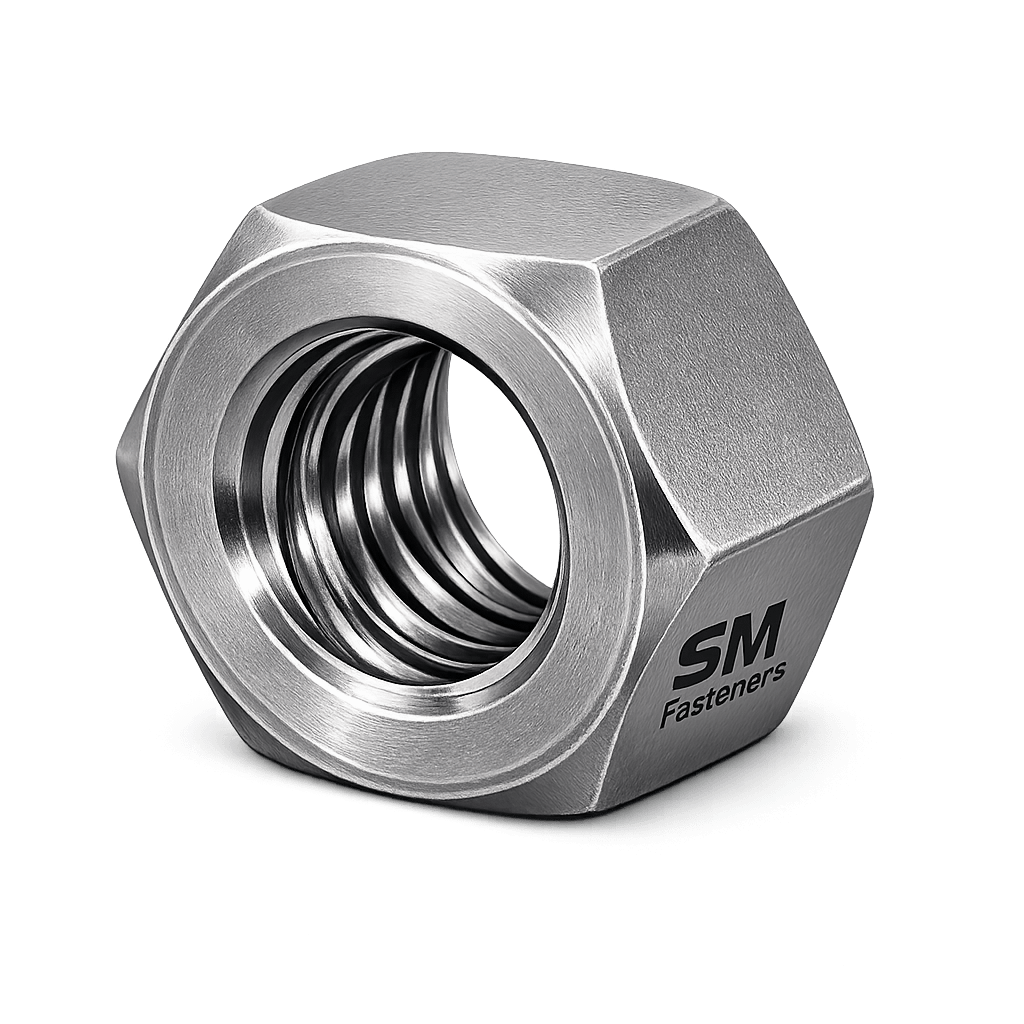
A Distorted Thread Nut is a prevailing torque self-locking nut incorporating intentional geometric deformation of the internal thread section.
Unlike nylon insert nuts, locking performance is achieved purely through metal-to-metal elastic interference.
Engineering Definition
A distorted thread nut generates locking torque through controlled thread deformation that creates radial pressure between mating threads, increasing frictional resistance to rotation independent of clamp load.
Fundamental Characteristics
| Parameter | Description |
|---|---|
| Locking Mechanism | Metallic prevailing torque |
| Insert Material | None |
| Temperature Capability | High-temperature compatible |
| Reusability | Limited, controlled cycles |
| Vibration Resistance | Excellent |
| Chemical Resistance | Same as base material |
| Compliance | Aerospace, Oil & Gas, Structural |
1.3 Functional Role in Bolted Assemblies
Distorted thread nuts perform three simultaneous functions:
- Clamp Load Generation
- Vibration Loosening Resistance
- Thread Friction Stabilization
They eliminate dependence on:
- Lock washers
- Double nutting
- Adhesives
- Chemical locking compounds
1.4 Load Mechanics & Force Behavior
Standard Bolted Joint Forces
When torque is applied:
- Bolt elongates elastically
- Joint members compress
- Preload (Fp) is generated
Where:
| Symbol | Meaning |
|---|---|
| T | Applied Torque |
| K | Nut Factor |
| D | Nominal Diameter |
Worked Example
For an M16 distorted thread nut:
- Torque (T) = 210 Nm
- Nut factor (K) = 0.20
- Diameter (D) = 0.016 m
This preload creates friction preventing joint separation.
1.5 Prevailing Torque Principle
Distortion produces:
- Localized elastic interference
- Increased flank pressure
- Additional rotational resistance
Total tightening torque becomes:
Where prevailing torque exists even without clamp load.
Resulting Engineering Advantages
- Prevents self-loosening under vibration
- Maintains preload during thermal cycles
- Improves fatigue resistance
- Eliminates secondary locking components
1.6 Types of Thread Distortion
Common distortion mechanisms:
| Type | Mechanism |
|---|---|
| Top Lock | Elliptical deformation at nut top |
| Center Lock | Mid-body distortion |
| Tri-Lobe | Three-point compression |
| Oval Lock | Ovalized thread profile |
| Stover Type | Axially compressed top section |
SM Fasteners manufactures distortion profiles aligned with international design tolerances.
1.7 Joint Design Principles
Critical Design Factors
Engineers must evaluate:
- Clamp load requirement
- Vibration amplitude
- Joint stiffness ratio
- Temperature exposure
- Assembly frequency
- Maintenance interval
Joint Stiffness Ratio
Where:
- = Bolt stiffness
- = Joint stiffness
Higher stiffness joints benefit most from distorted thread locking.
1.8 Torque–Tension Relationship
Approximate torque distribution:
| Torque Usage | Percentage |
|---|---|
| Thread friction | 40–50% |
| Bearing friction | 35–45% |
| Bolt preload | 10–15% |
| Prevailing torque | Additional controlled resistance |
1.9 Friction & Nut Factor Behavior
Distorted thread nuts intentionally increase friction.
Typical nut factors:
| Condition | Nut Factor (K) |
|---|---|
| Dry | 0.22 – 0.25 |
| Zinc plated | 0.18 – 0.22 |
| PTFE coated | 0.12 – 0.16 |
| MoS₂ coated | 0.10 – 0.14 |
Correct torque adjustment is essential during specification.
1.10 Failure Mechanisms Addressed
1. Vibration Loosening
Primary mitigation purpose.
2. Fatigue Failure
Stable preload reduces cyclic stress.
3. Joint Separation
Maintained clamp force prevents slip.
4. Thermal Relaxation
Metallic locking unaffected by temperature.
5. Hydrogen Embrittlement Risk
Controlled through coating selection and baking procedures under ISO 4042.
6. Stress Corrosion Cracking
Material selection critical for chloride and H₂S environments.
1.11 Application-Based Selection Logic
| Application | Recommended Design |
|---|---|
| Oil & Gas equipment | Stover distorted thread |
| Structural steel | Top-lock hex |
| Automotive | Tri-lobe lock |
| Railways | All-metal prevailing torque |
| Power plants | High-temp alloy distorted nut |
| Offshore | Duplex stainless distorted nut |
1.12 Comparison vs Other Locking Methods
| Method | Temperature | Reusable | Reliability |
|---|---|---|---|
| Nylon insert lock nut | Limited | Medium | Moderate |
| Lock Washer | Unlimited | High | Low |
| Adhesive | Medium | No | Medium |
| Double Nut | Unlimited | Yes | Medium |
| Distorted Thread Nut | Excellent | Controlled | High |
1.13 Engineering Advantages for EPC Projects
- Reduced part count
- Simplified assembly
- Lower lifecycle maintenance
- Enhanced safety compliance
- Predictable torque values
- Audit-friendly fastening solution
1.14 SM Fasteners Engineering Position
SM Fasteners manufactures distorted thread nuts under controlled ISO 9001 quality systems ensuring:
Global EPC project readiness
Dimensional consistency
Verified prevailing torque performance
Full material traceability
2. PRODUCT TYPES, GEOMETRY, DIMENSIONAL LOGIC & INTERNATIONAL STANDARDS
2.1 Product Classification — Distorted Thread Nut Family
Distorted thread nuts belong to the category:
All-Metal Prevailing Torque Self-Locking Nuts
The locking action is achieved through permanent geometric deformation of selected thread zones.
Unlike insert-lock nuts, performance remains stable across:
- High temperature service
- Chemical exposure
- Offshore environments
- Heavy cyclic loading
SM Fasteners manufactures distorted thread nuts aligned with global industrial specifications required by EPC contractors and OEM assemblies.
2.2 Major Product Types & Variants
2.2.1 Top Lock Distorted Thread Nut (Stover Nut)
Most widely used industrial variant.
Geometry Characteristics
- Upper threads compressed radially
- Circular distortion applied post forming
- Metal-to-metal interference
Engineering Use
- Structural steel
- Heavy equipment
- Oil & Gas piping supports
- Power plant installations
2.2.2 Oval Distorted Thread Nut
Thread cross-section slightly ovalized.
Characteristics
- Uniform locking torque
- Reduced galling risk
- Better torque consistency
Applications
- Automotive assemblies
- Railway equipment
- Machinery housings
2.2.3 Tri-Lobe Distorted Nut
Three-point deformation applied around circumference.
Advantages
- Balanced locking force
- Lower installation torque variation
- Improved reusability
Used extensively in OEM manufacturing.
2.2.4 Center Lock Distorted Nut
Distortion positioned mid-height of nut.
Engineering Benefits
- Stable preload retention
- Reduced bearing surface deformation
- Suitable for automated assembly
2.2.5 Heavy Hex Distorted Thread Nut
Designed for high-load structural joints.
Used in:
- Offshore platforms
- Pressure vessels
- Flange assemblies
- Petrochemical plants
Variant Comparison Table
| Type | Lock Location | Reuse Cycles | Load Capacity | Typical Industry |
|---|---|---|---|---|
| Stover | Top | Medium | High | Structural/Oil & Gas |
| Oval | Full section | Medium | Medium | Automotive |
| Tri-Lobe | 3 points | High | Medium | OEM |
| Center Lock | Mid | Medium | High | Machinery |
| Heavy Hex | Top | Medium | Very High | EPC Projects |
2.3 Dimensional Logic & Engineering Geometry
Correct nut geometry ensures:
- Proper wrench engagement
- Thread engagement length
- Load distribution
- Bearing surface integrity
Key design parameters:
| Parameter | Engineering Function |
|---|---|
| Across Flats (S) | Torque transmission |
| Nut Height (m) | Thread engagement strength |
| Pitch | Load distribution |
| Bearing Face | Surface pressure control |
| Distortion Zone | Locking torque generation |
Engineering Rule — Thread Engagement
Minimum engagement:
Where:
- = Engagement length
- = Bolt diameter
High-strength assemblies may require 1.25D engagement.
2.4 Standard Metric Dimensional Specifications
ISO Metric Distorted Thread Nut Dimensions
| Size | Pitch (mm) | Across Flats S (mm) | Height m (mm) | Typical Weight (kg/100 pcs)* |
|---|---|---|---|---|
| M6 | 1.0 | 10 | 5 | 0.45 |
| M8 | 1.25 | 13 | 6.5 | 0.95 |
| M10 | 1.5 | 17 | 8 | 1.80 |
| M12 | 1.75 | 19 | 10 | 3.20 |
| M16 | 2.0 | 24 | 13 | 7.10 |
| M20 | 2.5 | 30 | 16 | 13.5 |
| M24 | 3.0 | 36 | 19 | 24.0 |
| M30 | 3.5 | 46 | 24 | 46.5 |
*Weights aligned with SM Fasteners production data ranges.
2.5 Unified Thread Series (Inch Standards)
Widely required for US EPC projects.
| Size | Thread | Across Flats (in) | Height (in) |
|---|---|---|---|
| 1/4″ | UNC/UNF | 7/16 | 7/32 |
| 3/8″ | UNC/UNF | 9/16 | 11/32 |
| 1/2″ | UNC/UNF | 3/4 | 7/16 |
| 5/8″ | UNC/UNF | 15/16 | 35/64 |
| 3/4″ | UNC/UNF | 1-1/8 | 21/32 |
| 1″ | UNC/UNF | 1-1/2 | 7/8 |
2.6 Applicable International Standards
Distorted thread nuts may be supplied according to multiple global standards.
ISO Standards
| Standard | Scope |
|---|---|
| ISO 7042 | All-metal prevailing torque hex nuts |
| ISO 10512 | Prevailing torque type hex nuts |
| ISO 2320 | Prevailing torque performance testing |
| ISO 898-2 | Mechanical properties of nuts |
| ISO 965 | Thread tolerances |
DIN Standards
| DIN Standard | Description |
|---|---|
| DIN 980 | All-metal self-locking nuts |
| DIN 982 | Locking hex nuts |
| DIN 6927 | Flanged locking nuts |
ASTM Standards
| ASTM | Application |
|---|---|
| ASTM A563 | Carbon & alloy steel nuts |
| ASTM A194 | High-pressure/high-temp nuts |
| ASTM F594 | Stainless steel nuts |
| ASTM B637 | Nickel alloy fasteners |
British Standards
| BS Standard | Coverage |
|---|---|
| BS 3692 | ISO metric nuts |
| BS 1768 | Hexagon fasteners |
| BS EN ISO 2320 | Locking performance |
2.7 Thread Standards & Tolerances
| Thread System | Standard | Typical Class |
|---|---|---|
| Metric | ISO 261 / 965 | 6H |
| UNC | ASME B1.1 | 2B |
| UNF | ASME B1.1 | 2B |
| BSW | BS 84 | Medium |
| BSF | BS 84 | Fine |
Tolerance selection ensures:
- Controlled interference
- Consistent prevailing torque
- Interchangeability worldwide
2.8 Prevailing Torque Requirements (ISO 2320)
ISO 2320 defines:
- Minimum locking torque
- Maximum installation torque
- Removal torque after cycles
Example performance range:
| Size | Minimum Prevailing Torque (Nm) |
|---|---|
| M8 | 1.5 |
| M10 | 3 |
| M12 | 5 |
| M16 | 12 |
| M20 | 20 |
| M24 | 35 |
Values verified during production testing at SM Fasteners.
2.9 Property Class System (Metric Nuts)
Mechanical capability follows ISO 898-2.
| Property Class | Compatible Bolt Class | Application |
|---|---|---|
| 5 | 5.8 | Light structures |
| 8 | 8.8 | General engineering |
| 10 | 10.9 | Heavy machinery |
| 12 | 12.9 | Critical structural |
Rule:Nut Class≥Bolt Class
2.10 Heavy Hex vs Standard Hex Geometry
| Feature | Standard Hex | Heavy Hex |
|---|---|---|
| Across Flats | Smaller | Larger |
| Bearing Area | Moderate | High |
| Load Capacity | Medium | High |
| Preferred Sector | Machinery | Oil & Gas EPC |
2.11 Engineering Interchangeability Considerations
Global projects frequently combine components from multiple regions.
SM Fasteners ensures compatibility with:
- European ISO designs
- American ASTM systems
- British legacy installations
- Middle East EPC specifications
Critical checks:
- Thread pitch matching
- Property class alignment
- Coating compatibility
- Temperature rating
2.12 Dimensional Inspection Requirements
Typical tolerances verified during manufacturing:
| Feature | Inspection Method |
|---|---|
| Thread pitch | Go/No-Go gauges |
| Across flats | Digital caliper |
| Height | Micrometer |
| Concentricity | Optical inspection |
| Distortion profile | Torque validation test |
2.13 Weight Reference Chart
(SM Fasteners Engineering Logistics Data)
| Size | Weight/Piece (kg) | Weight/100 pcs (kg) |
|---|---|---|
| M8 | 0.009 | 0.90 |
| M10 | 0.018 | 1.80 |
| M12 | 0.032 | 3.20 |
| M16 | 0.071 | 7.10 |
| M20 | 0.135 | 13.50 |
| M24 | 0.240 | 24.00 |
| M30 | 0.465 | 46.50 |
Used for EPC shipping estimation and export packing calculations.
2.14 Engineering Design Guidance
Distorted thread nuts should be specified when:
- Vibration amplitude exceeds 0.3 g
- Maintenance intervals exceed 2 years
- Lock washers are prohibited
- High temperature exceeds 120°C
- Chemical exposure exists
2.15 SM Fasteners Capability Integration
Under ISO 9001 manufacturing control, SM Fasteners provides:
- Standard and heavy hex distorted thread nuts
- Metric & imperial thread supply
- Custom distortion geometry engineering
- EPC documentation-ready production
- Global interchangeability assurance
Available in:
- Stainless Steel
- Alloy Steel
- Duplex & Super Duplex
- Nickel Alloys
- High-performance PEEK locking fasteners for electrically insulated assemblies.
3. MATERIAL ENGINEERING, HEAT TREATMENT, MANUFACTURING WORKFLOW & SURFACE ENGINEERING
3.1 Materials Engineering Philosophy
Material selection for distorted thread nuts directly determines:
- Load carrying capacity
- Prevailing torque stability
- Corrosion resistance
- Temperature capability
- Resistance to galling and stress corrosion cracking
Because distorted thread nuts rely on elastic deformation, materials must exhibit:
- Controlled hardness
- Adequate ductility
- Stable yield strength
- Resistance to relaxation
SM Fasteners manufactures distorted thread nuts across a full industrial material spectrum aligned with global EPC specifications.
3.2 Industrial Material Grades
Carbon Steel Grades
Used where strength and cost efficiency are primary requirements.
| Standard | Typical Grade | Property Class | Application |
|---|---|---|---|
| ISO | C35 / C45 | 8, 10 | Structural assemblies |
| ASTM | A563 Grade A/DH | Structural bolting | |
| ASTM | A194 Grade 2H | Pressure vessels | |
| BS | EN8 | General engineering |
Advantages
- High strength
- Economical
- Excellent machinability
Limitations
- Requires coating for corrosion protection.
Alloy Steel Grades
Designed for heavy load and elevated temperature environments.
| Standard | Grade | Use |
|---|---|---|
| ASTM A194 | 2H / 7 / 7M | High-pressure flanges |
| EN 10083 | 42CrMo4 | Heavy equipment |
| ASTM A320 | L7/L7M | Low-temperature service |
Applications:
- Oil & Gas flanges
- Power plants
- Structural heavy joints
Stainless Steel Grades
Provide corrosion resistance with reliable locking performance.
| Grade | Equivalent | Environment |
|---|---|---|
| A2-70 | 304 | General industrial |
| A4-70 | 316 | Marine & chemical |
| A4-80 | 316H | Offshore |
| 321 | Stabilized | High temperature |
| 904L | Super austenitic | Acidic service |
Duplex & Super Duplex Stainless Steel
Used where strength + corrosion resistance are simultaneously required.
| Material | Standard | Features |
|---|---|---|
| Duplex 2205 | UNS S31803 | High strength + chloride resistance |
| Super Duplex 2507 | UNS S32750 | Offshore & subsea |
Advantages:
- Double strength vs austenitic SS
- Excellent SCC resistance
- Reduced weight requirements
Nickel & High-Performance Alloys
Critical for extreme environments.
| Alloy | Standard | Application |
|---|---|---|
| Inconel 625 | ASTM B637 | LNG & turbines |
| Inconel 718 | High temp fasteners | |
| Hastelloy C276 | Chemical reactors | |
| Monel 400 | Seawater systems | |
| Incoloy 825 | Acid service | |
| SMO 254 | Chloride environments |
PEEK Fastener Variant
SM Fasteners also engineers PEEK distorted thread locking nuts for specialized applications.
Characteristics
- Non-metallic locking action
- Electrically insulating
- Lightweight
- Chemical resistant
- Non-magnetic
Applications:
- Semiconductor manufacturing
- Electrical panels
- Medical equipment
- Aerospace electronics
3.3 Material Comparison Table
| Material | UTS (MPa) | Yield (MPa) | Corrosion Resistance | Temp Limit | Relative Cost | Typical Sector |
|---|---|---|---|---|---|---|
| Carbon Steel | 800 | 640 | Low | 300°C | Low | Construction |
| Alloy Steel | 1040 | 940 | Medium | 450°C | Medium | Oil & Gas |
| SS 304 | 700 | 450 | Good | 400°C | Medium | Industrial |
| SS 316 | 720 | 480 | Excellent | 450°C | Medium-High | Offshore |
| Duplex 2205 | 850 | 620 | Excellent | 300°C | High | Marine |
| Super Duplex | 1000 | 750 | Outstanding | 300°C | Very High | Subsea |
| Inconel 718 | 1250 | 1030 | Exceptional | 700°C | Premium | Aerospace |
| PEEK | — | — | Excellent | 260°C | High | Electrical |
3.4 Corrosion Resistance vs Environment
| Environment | Recommended Material |
|---|---|
| Seawater | Duplex / Super Duplex |
| H₂S Sour Service | ASTM A194 7M / Duplex |
| Chlorides | SMO 254 / Super Duplex |
| Acids | Hastelloy |
| High Temperature | Inconel |
| Chemical Processing | 316 / Alloy Steel |
| Electrical Insulation | PEEK |
All sour-service materials comply with NACE MR0175 / ISO 15156 hardness requirements.
3.5 Heat Treatment Processes
Heat treatment is critical because distorted thread nuts require elastic recovery for locking performance.
Typical Heat Treatment Workflow
- Austenitizing
- Quenching
- Tempering
- Stress relieving
- Hardness verification
Heat Treatment Objectives
| Objective | Result |
|---|---|
| Increase strength | Higher proof load |
| Improve toughness | Reduced brittleness |
| Maintain ductility | Stable distortion zone |
| Prevent cracking | Reliable service life |
Hardness Control (Typical)
| Property Class | Hardness Range |
|---|---|
| Class 8 | 22–30 HRC |
| Class 10 | 26–36 HRC |
| Class 12 | 32–39 HRC |
For sour service:
- Hardness ≤ 22 HRC (NACE compliant)
3.6 Manufacturing Workflow — SM Fasteners Production System
SM Fasteners operates under ISO 9001-certified manufacturing controls.
Step 1 — Raw Material Verification
- Approved mill sourcing
- Chemical composition validation
- EN 10204 3.1 MTC verification
- Heat number traceability
Step 2 — Forging / Cold Forming
Preferred manufacturing method:
Cold Forging
- Superior grain flow
- Higher fatigue strength
- Reduced machining waste
Large sizes may use hot forging.
Step 3 — Machining Operations
- Facing
- Chamfering
- Washer face preparation
- Precision boring (special alloys)
Step 4 — Thread Formation
Thread Rolling (Preferred)
Advantages:
- Work hardening
- Improved fatigue resistance
- Smooth surface finish
Thread Cutting
Used for:
- Exotic alloys
- Large diameters
- Low-volume custom orders
Step 5 — Distortion Formation
Critical proprietary process.
Methods include:
- Mechanical pressing
- Ovalization tooling
- Controlled radial compression
- Multi-point deformation dies
Process control ensures:
- Repeatable prevailing torque
- No thread cracking
- Uniform locking force
Step 6 — Heat Treatment
Performed in calibrated furnaces with:
- Temperature recording
- Batch traceability
- Controlled atmosphere
Step 7 — Surface Finishing
Cleaning and preparation before coating.
Step 8 — Final Inspection & Traceability
Each production batch linked to:
- Heat number
- Operator records
- Inspection reports
- Test results
3.7 Surface Engineering & Coatings
Surface finish selection affects:
- Corrosion resistance
- Friction coefficient
- Torque values
- Hydrogen embrittlement risk
Surface Finish Comparison Table
| Coating | Corrosion Protection | Temp Limit | Friction | Typical Use |
|---|---|---|---|---|
| Plain Oil | Low | High | Medium | Indoor |
| Zinc Plated | Medium | 120°C | Low | General |
| HDG | High | 300°C | High | Structural |
| Mechanical Galv. | Medium | 200°C | Medium | Automotive |
| Dacromet | Very High | 300°C | Low | Offshore |
| PTFE | Excellent | 260°C | Very Low | Chemical |
| Xylan | Excellent | 260°C | Controlled | Oil & Gas |
| Phosphate + Oil | Moderate | High | Stable | Machinery |
Hydrogen Embrittlement Control
Mandatory for high-strength nuts:
- Post-plating baking
- ISO 4042 compliance
- Hardness monitoring
3.8 Surface Friction vs Torque Influence
| Surface Condition | Nut Factor K |
|---|---|
| Dry | 0.22–0.25 |
| Zinc Plated | 0.18–0.22 |
| PTFE | 0.12–0.16 |
| MoS₂ | 0.10–0.14 |
Torque values must always reflect coating condition.
3.9 Manufacturing Quality Advantages — SM Fasteners
Through integrated manufacturing systems, SM Fasteners ensures:
- Controlled distortion geometry
- Stable prevailing torque performance
- Full metallurgy validation
- Compatibility with EPC specifications
- Capability for custom engineered locking solutions
Available supply includes:
- Standard production sizes
- Heavy hex variants
- Custom distortion designs
- Special alloy fasteners
- PEEK engineered solutions
4 — INSPECTION, QUALITY CONTROL, APPLICATIONS, EXPORT READINESS & ENGINEERING TABLES
4.1 Inspection & Quality Control Philosophy
Distorted thread nuts are classified as safety-critical fastening components in EPC, structural, pressure equipment, and rotating machinery installations.
Because locking performance depends on controlled deformation, inspection must validate:
- Dimensional accuracy
- Mechanical strength
- Prevailing torque performance
- Material integrity
- Surface condition
- Traceability
SM Fasteners operates an ISO 9001 certified quality management system integrated with MSME and UKAF accreditation requirements ensuring audit-ready manufacturing and inspection compliance.
4.2 Incoming Material Inspection
Before production release, all raw materials undergo verification.
Raw Material Validation
| Inspection | Method | Purpose |
|---|---|---|
| Chemical composition | Spectrometer / PMI | Alloy confirmation |
| Mill Test Certificate | EN 10204 3.1 | Traceability |
| Visual inspection | Surface review | Defect elimination |
| Hardness check | Rockwell test | Material compliance |
| Heat number marking | Batch traceability | Lifecycle tracking |
4.3 In-Process Manufacturing Inspection
| Stage | Inspection Activity |
|---|---|
| Forging | Grain flow verification |
| Machining | Dimensional tolerance check |
| Threading | Go / No-Go gauges |
| Distortion forming | Prevailing torque validation |
| Heat treatment | Furnace temperature recording |
| Coating | Thickness measurement |
4.4 Final Inspection & Mechanical Testing
Mechanical Property Verification
| Test | Standard | Objective |
|---|---|---|
| Proof load test | ISO 898-2 | Load capacity |
| Hardness test | ISO 6508 | Heat treatment verification |
| Tensile compatibility | ISO 898 | Bolt matching |
| Prevailing torque test | ISO 2320 | Locking performance |
| Coating adhesion | ASTM B571 | Coating reliability |
4.5 Non-Destructive Testing (NDT)
Applied for critical project requirements.
| Method | Purpose |
|---|---|
| Magnetic Particle Inspection | Surface crack detection |
| Dye Penetrant | Fine crack detection |
| Ultrasonic Testing | Internal flaws |
| PMI Testing | Alloy verification |
| Visual inspection | Surface integrity |
4.6 Traceability & Documentation
Every SM Fasteners batch can be traced from raw material to shipment.
Standard Documentation Package
- EN 10204 3.1 Material Test Certificate
- Heat Treatment Report
- Dimensional Inspection Report
- Prevailing Torque Test Record
- Coating Certificate
- Certificate of Conformity (CoC)
- Packing List & Traceability Labels
Optional:
- 3.2 Third-Party Inspection (BV, TUV, SGS equivalent)
4.7 Mechanical Properties Table (Grade-Wise)
| Property Class | Proof Load (MPa) | Compatible Bolt | Typical Use |
|---|---|---|---|
| Class 5 | 500 | 5.8 | Light assemblies |
| Class 8 | 800 | 8.8 | General engineering |
| Class 10 | 1000 | 10.9 | Heavy equipment |
| Class 12 | 1200 | 12.9 | Critical joints |
4.8 Proof Load & Tensile Capacity (Typical Values)
| Size | Class 8 Proof Load (kN) | Class 10 Proof Load (kN) | Class 12 Proof Load (kN) |
|---|---|---|---|
| M8 | 23 | 29 | 34 |
| M10 | 36 | 45 | 52 |
| M12 | 52 | 65 | 75 |
| M16 | 95 | 118 | 138 |
| M20 | 148 | 185 | 215 |
| M24 | 213 | 266 | 310 |
4.9 Tightening Torque Chart
(General Engineering Reference — Final torque depends on lubrication and coating)
| Size | Class 8 Dry (Nm) | Class 8 Lubricated (Nm) | Class 10 Lubricated (Nm) |
|---|---|---|---|
| M8 | 25 | 18 | 26 |
| M10 | 49 | 35 | 50 |
| M12 | 86 | 61 | 87 |
| M16 | 210 | 150 | 214 |
| M20 | 410 | 290 | 415 |
| M24 | 710 | 500 | 715 |
Prevailing torque must be added to installation torque during assembly planning.
4.10 Preload Calculation — Engineering Method
Formula
Where:
- = Preload Force
- = Torque
- = Nut Factor
- = Nominal Diameter
Worked Example — EPC Structural Joint
Bolt Size: M20
Torque: 410 Nm
Nut Factor: 0.18 (lubricated)
Diameter: 0.020 m
This preload ensures joint integrity under dynamic loads.
4.11 Failure Modes & Prevention
| Failure Mode | Cause | Prevention |
|---|---|---|
| Self-loosening | Vibration | Distorted thread locking |
| Fatigue cracking | Preload loss | Correct torque |
| Galling | Stainless friction | Lubrication / coating |
| Hydrogen embrittlement | Electroplating | Controlled baking |
| Stress corrosion cracking | Chlorides | Material upgrade |
| Thread stripping | Grade mismatch | Correct property class |
4.12 Industry Applications
Construction & Structural Steel
- Steel frames
- Bridges
- Transmission towers
- Seismic structures
Oil & Gas Industry
Upstream
- Wellhead assemblies
- Drilling rigs
Midstream
- Pipeline supports
- Compressor skids
Downstream
- Refineries
- Process piping
NACE-compliant distorted thread nuts widely specified.
Power Generation
- Turbine housings
- Boiler structures
- Nuclear auxiliary systems
- Wind turbine towers
Petrochemical & Chemical Processing
- Reactor supports
- Pump assemblies
- Heat exchangers
- Corrosion-critical equipment
LNG & Offshore Platforms
Preferred due to:
- No polymer inserts
- High temperature tolerance
- Long maintenance cycles
Materials:
- Duplex
- Super Duplex
- Inconel
Automotive & Heavy Equipment
- Suspension systems
- Axle assemblies
- Mining machinery
- Earthmoving equipment
Railways & Infrastructure
- Track equipment
- Signal structures
- Rolling stock assemblies
Shipbuilding & Marine
- Deck machinery
- Propulsion equipment
- Corrosion-resistant bolting
PEEK Fastener Applications
SM Fasteners supplies engineered PEEK locking fasteners for:
- Electrical insulation systems
- Semiconductor equipment
- Medical machinery
- EMI-sensitive assemblies
4.13 Thread Standards & Tolerance Table
| System | Standard | Class |
|---|---|---|
| Metric | ISO 261 / ISO 965 | 6H |
| UNC | ASME B1.1 | 2B |
| UNF | ASME B1.1 | 2B |
| BSW | BS 84 | Medium |
| BSF | BS 84 | Fine |
Ensures global interchangeability across EPC projects.
4.14 Surface Finish Performance vs Environment
| Environment | Recommended Coating |
|---|---|
| Indoor industrial | Zinc plating |
| Offshore marine | PTFE / Xylan |
| Structural outdoor | Hot Dip Galvanized |
| Chemical plants | Fluoropolymer coating |
| High temperature | Plain / Phosphate |
| Sour service | NACE compliant coating |
4.15 Weight Chart — Logistics & EPC Planning
(Aligned with SM Fasteners manufacturing data)
| Size | Weight/Piece (kg) | Weight/100 pcs (kg) |
|---|---|---|
| M8 | 0.009 | 0.90 |
| M10 | 0.018 | 1.80 |
| M12 | 0.032 | 3.20 |
| M16 | 0.071 | 7.10 |
| M20 | 0.135 | 13.50 |
| M24 | 0.240 | 24.00 |
| M30 | 0.465 | 46.50 |
Used for freight optimization and container planning.
4.16 Industrial Packaging & Export Preparation
SM Fasteners follows export-grade packaging standards.
Primary Protection
- Thread protection
- Anti-corrosion oil
- VCI packaging
- Batch labeling
Secondary Packaging
- Heavy-duty cartons
- Moisture barrier wrapping
- Palletized loads
Export Crating
- ISPM-15 fumigated wooden crates
- Shock protection
- Container load optimization
4.17 Global Export Capability
SM Fasteners supplies distorted thread nuts to:
- Middle East EPC projects
- European industrial buyers
- North American OEMs
- Southeast Asian infrastructure projects
Capabilities include:
- Metric & Imperial standards
- Custom manufacturing
- Exotic alloy production
- Low and high volume supply
4.18 Engineering Procurement Support
Provided to EPC and OEM clients:
- Material selection consultation
- Torque recommendations
- Drawing review support
- Custom distortion design
- Project documentation packages
4.19 Integration with ISO 9001 Quality System
SM Fasteners quality framework ensures:
- Controlled manufacturing processes
- Documented inspection stages
- Continuous improvement programs
- Supplier qualification systems
- Audit-ready traceability
4.20 Engineering Summary
Distorted thread nuts represent one of the most reliable mechanical locking technologies available for industrial bolted joints.
Through controlled deformation, they provide:
- Permanent vibration resistance
- High-temperature stability
- Predictable preload retention
- Reduced maintenance risk
Combined with certified manufacturing, advanced materials capability, and global documentation compliance, SM Fasteners delivers distorted thread nuts engineered for demanding EPC, energy, infrastructure, and heavy industrial applications worldwide.