SERRATED FLANGE
1 — INDUSTRY CONTEXT, FUNCTIONAL MECHANICS & JOINT DESIGN PRINCIPLES
1.1 Industrial Context of Serrated Flange Fasteners
Serrated flange fasteners represent an engineered evolution of conventional bolting systems developed to address joint loosening under vibration, cyclic loading, and dynamic operational environments.
Modern industrial assemblies increasingly operate under:
- High-frequency vibration
- Thermal expansion cycling
- Shock loading
- Rotational forces
- Maintenance-limited installations
Industries such as oil & gas, heavy equipment manufacturing, offshore platforms, structural steel erection, rail systems, and power generation demand fastening solutions that combine:
- High clamp load retention
- Reduced assembly complexity
- Controlled friction behavior
- Reliable anti-loosening performance
Serrated flange configurations integrate washer functionality directly into the fastener, eliminating secondary components while improving joint integrity.
At SM Fasteners, serrated flange products are manufactured under ISO 9001 certified quality systems, supporting EPC contractors, OEM manufacturers, and global procurement organizations requiring audit-ready fastener solutions.
1.2 Technical Definition
A Serrated Flange Fastener (bolt or nut) incorporates:
- Integral flange face
- Radial serrations beneath bearing surface
- Threaded fastening body
Structural Elements
| Component | Function |
|---|---|
| Hex Head Nut / Nut Body | Torque transmission |
| Integral Flange | Load distribution |
| Serrations | Mechanical locking |
| Thread | Preload generation |
| Bearing Surface | Friction stabilization |
Unlike standard hex fasteners requiring washers, serrated flange fasteners perform three functions simultaneously:
- Clamping
- Load spreading
- Anti-rotation locking
1.3 Functional Principle of Serrations
Serrations are precision-machined or forged radial teeth oriented opposite tightening direction.
During Tightening:
- Fastener torque generates axial tension.
- Flange distributes contact pressure.
- Serrations plastically embed into mating surface.
- Micro-biting action increases resistance to rotation.
Resulting Benefits
- Increased prevailing torque
- Reduced loosening tendency
- Higher vibration resistance
- Lower dependency on thread friction
1.4 Load Mechanics & Force Behavior
Serrated flange fasteners operate fundamentally as preloaded tension members.
1.4.1 Preload Generation
Applied torque produces axial tension:
Where:
- F = Preload force (N)
- T = Applied torque (Nm)
- K = Nut factor (0.12–0.22)
- D = Nominal diameter (m)
1.4.2 Load Transfer Mechanism
External loads should ideally never reach bolt shear capacity.
Correct joint design ensures:
External Load → Joint Compression → Friction Resistance → Bolt remains elastic
Serrated flange geometry enhances:
- Contact friction coefficient
- Slip resistance
- Clamp load stability
1.4.3 Contact Stress Distribution
The flange increases effective bearing diameter.
| Fastener Type | Contact Area | Stress Distribution |
|---|---|---|
| Standard Hex + Washer | Moderate | Localized |
| Hex Without Washer | Low | High Stress |
| Serrated Flange | High | Uniform |
Reduced bearing stress prevents:
- Surface galling
- Joint embedding loss
- Relaxation failures
1.5 Torque–Tension Relationship
Torque applied to a fastener is consumed as:
| Torque Usage | Percentage |
|---|---|
| Thread friction | 40–50% |
| Bearing friction | 35–45% |
| Useful preload | 10–15% |
Serrations stabilize bearing friction variability, improving preload repeatability.
1.6 Friction Mechanics & Nut Factor
Typical Nut Factor Values:
| Condition | Nut Factor (K) |
|---|---|
| Dry Carbon Steel | 0.20 |
| Zinc Plated | 0.18 |
| Lubricated | 0.14 |
| PTFE Coated | 0.12 |
Serrated flanges reduce friction fluctuation during service rather than during tightening.
1.7 Joint Design Principles
Fundamental Engineering Rules
- Clamp force must exceed service load.
- Fastener must remain in elastic region.
- Joint separation must never occur.
- Friction must resist transverse motion.
Recommended Joint Stack
✔ Structural member
✔ Flat mating surface
✔ Serrated flange fastener
✘ Washer typically unnecessary
When Serrated Flange Fasteners Are Preferred
| Condition | Suitability |
|---|---|
| High vibration | Excellent |
| Automotive assemblies | Preferred |
| Thin plate structures | Highly effective |
| Repetitive maintenance | Suitable |
| Rotating equipment | Recommended |
1.8 Mechanical Behavior Under Service Conditions
1.8.1 Vibration Resistance
Serrations create mechanical interlock preventing self-loosening described by the Junker vibration model.
1.8.2 Fatigue Performance
Maintained preload reduces alternating stress amplitude.
Higher retained preload → Lower fatigue failure probability.
1.8.3 Slip Resistance
Flange increases frictional resistance:
Where μ increases due to serration bite.
1.9 Failure Mechanisms and Engineering Control
Fatigue Failure
Cause:
- Preload loss
- Cyclic loading
Mitigation:
- Proper torque control
- High-strength grades
- Serrated flange usage
Shear Failure
Occurs when:
- Joint separation occurs
- Load bypasses friction interface
Prevention:
- Correct preload ratio
- Adequate thread engagement
Hydrogen Embrittlement
Risk materials:
- High-strength carbon steels (>1000 MPa)
Controls:
- Baking after plating
- Controlled electroplating processes
- SM Fasteners verified coating systems
Stress Corrosion Cracking (SCC)
Affected Materials:
- Austenitic stainless steels in chlorides
- High-strength steels in H₂S
Solutions:
- Duplex alloys
- Nickel alloys
- NACE-compliant materials
1.10 Thread Engagement Requirements
Minimum engagement:
| Material | Required Engagement |
|---|---|
| Steel | 1 × diameter |
| Aluminum | 1.5 × diameter |
| Cast Iron | 1.25 × diameter |
1.11 Design Advantages Over Conventional Fasteners
| Parameter | Standard Hex | Serrated Flange |
|---|---|---|
| Washer Required | Yes | No |
| Assembly Time | Higher | Reduced |
| Vibration Resistance | Moderate | High |
| Clamp Retention | Variable | Stable |
| Inventory Complexity | High | Lower |
1.12 Engineering Selection Criteria
Mechanical Factors
- Required preload
- Dynamic loading
- Surface hardness
- Reusability requirement
Environmental Factors
- Temperature
- Corrosion exposure
- Chemical presence
- Offshore conditions
Procurement Factors
- Global standards compliance
- Traceability
- Inspection documentation
- Interchangeability
SM Fasteners designs serrated flange products aligned with international EPC specifications, ensuring compatibility with ISO, ASTM, DIN, and BS-based project documentation.
2 .PRODUCT TYPES, GEOMETRY, DIMENSIONAL LOGIC & INTERNATIONAL STANDARDS
2.1 Product Types and Engineering Variants
Serrated flange fastening systems are supplied in multiple engineered configurations depending on load requirement, assembly accessibility, vibration severity, and material compatibility.
At SM Fasteners, serrated flange products are manufactured through controlled forging and precision machining processes aligned with ISO 9001 quality management systems, ensuring dimensional repeatability and global interchangeability.
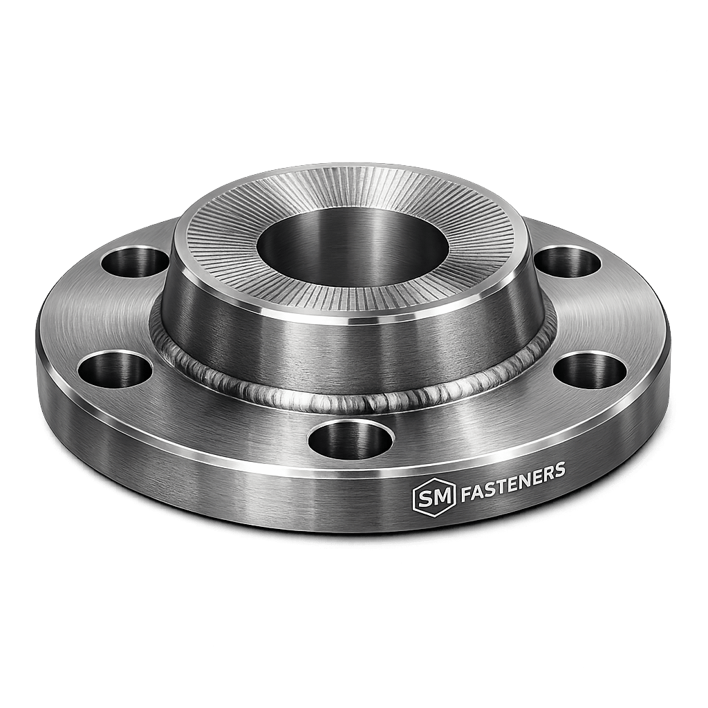
2.1.1 Serrated Flange Bolt
Description:
Hex head bolt incorporating an integral serrated washer face.
Key Functional Characteristics
- Eliminates loose washer
- Rapid installation
- Controlled bearing pressure
- High vibration resistance
Typical Uses
- Automotive frames
- Structural steel connections
- Machinery housings
- Rail assemblies
- Equipment panels
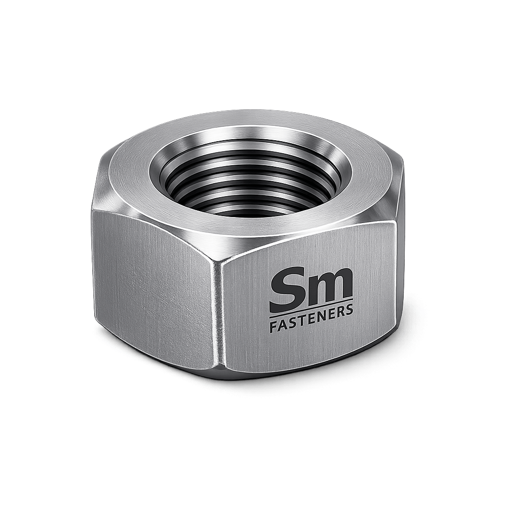
2.1.2 Serrated Flange Nut
Description:
Hex nut with integral flange and radial locking serrations.
Engineering Benefits
- Maintains preload under cyclic loading
- Reduces installation components
- Improved torque retention
Common Pairing
- With standard hex bolts
- Stud bolt assemblies
- Structural anchor systems
2.1.3 Serrated Flange Screw
Used where threaded holes exist.
Applications include:
- Motor housings
- Gearboxes
- Sheet metal assemblies
- Precision equipment
2.1.4 Metric vs Imperial Configurations
| System | Thread Type | Primary Regions |
|---|---|---|
| Metric | ISO Metric | Europe, Asia, Middle East |
| UNC | Unified Coarse | USA, Canada |
| UNF | Unified Fine | Aerospace & precision |
| BSW | British Standard Whitworth | Legacy infrastructure |
| BSF | British Standard Fine | Older mechanical equipment |
SM Fasteners supplies fully interchangeable thread systems supporting multinational EPC projects.
2.2 Geometry and Dimensional Logic
The effectiveness of serrated flange fasteners depends heavily on engineered geometry relationships.
2.2.1 Critical Design Dimensions
| Symbol | Parameter | Engineering Function |
|---|---|---|
| d | Nominal Diameter | Load capacity |
| P | Thread Pitch | Preload resolution |
| s | Hex Size | Tool interface |
| dc | Flange Diameter | Load distribution |
| k | Head Height | Torque strength |
| rf | Serration Depth | Locking efficiency |
2.2.2 Flange Diameter Engineering
Flange diameter is intentionally larger than hex bearing area.Dflange≈1.6−2.2×Bolt Diameter
Benefits:
- Reduced surface pressure
- Prevention of joint embedding
- Improved fatigue life
2.2.3 Serration Geometry
Key parameters:
| Parameter | Typical Range |
|---|---|
| Serration angle | 25°–40° |
| Tooth pitch | 0.5–1.5 mm |
| Penetration depth | 0.1–0.3 mm |
| Direction | Opposite tightening |
Engineering Purpose:
- Resist reverse rotation
- Maintain clamp load
2.3 Standard Dimensional Specification Table (Metric)
Serrated Flange Bolt Dimensions — ISO Pattern
| Size | Pitch (mm) | Hex (mm) | Flange Dia (mm) | Head Height (mm) |
|---|---|---|---|---|
| M5 | 0.8 | 8 | 11.8 | 3.5 |
| M6 | 1.0 | 10 | 14.2 | 4.0 |
| M8 | 1.25 | 13 | 17.9 | 5.3 |
| M10 | 1.5 | 15 | 21.8 | 6.4 |
| M12 | 1.75 | 18 | 26.0 | 7.5 |
| M16 | 2.0 | 24 | 34.9 | 10.0 |
| M20 | 2.5 | 30 | 42.8 | 12.5 |
(Values aligned with ISO flange bolt proportions used in EPC procurement.)
2.4 Serrated Flange Nut Dimensions
| Size | Pitch | Width Across Flats | Flange Diameter | Height |
|---|---|---|---|---|
| M6 | 1.0 | 10 | 14 | 6 |
| M8 | 1.25 | 13 | 17 | 8 |
| M10 | 1.5 | 15 | 21 | 10 |
| M12 | 1.75 | 18 | 25 | 12 |
| M16 | 2.0 | 24 | 34 | 16 |
| M20 | 2.5 | 30 | 42 | 20 |
2.5 Dimensional Logic for Load Distribution
Bearing Pressure Formula
Where:
- P = Bearing pressure
- F = Clamp load
- A = Flange contact area
Increasing flange area reduces localized stress, enabling thinner substrates without deformation.
2.6 Applicable International Standards
Serrated flange fasteners are governed by multiple global standards ensuring interchangeability.
2.6.1 ISO Standards
| Standard | Scope |
|---|---|
| ISO 4162 | Hex flange bolts |
| ISO 7044 | Prevailing torque nuts |
| ISO 898-1 | Mechanical properties of bolts |
| ISO 898-2 | Mechanical properties of nuts |
| ISO 965 | Thread tolerances |
| ISO 4032 | Hex nuts dimensions |
| ISO 16047 | Torque/clamp testing |
2.6.2 DIN Standards
| Standard | Description |
|---|---|
| DIN 6921 | Hex flange bolts |
| DIN 6923 | Flange nuts |
| DIN 267 | Mechanical testing |
| DIN EN ISO 3506 | Stainless fasteners |
2.6.3 ASTM Standards
| Standard | Application |
|---|---|
| ASTM A307 | Carbon steel bolts |
| ASTM A325 | Structural bolting |
| ASTM A449 | High strength |
| ASTM F594 | Stainless nuts |
| ASTM F593 | Stainless bolts |
| ASTM B633 | Zinc plating |
2.6.4 British Standards (BS)
| Standard | Application |
|---|---|
| BS 3692 | Metric fasteners |
| BS EN ISO 4017 | Hex bolts |
| BS 4190 | Unified threads |
2.7 Property Class System (Metric)
| Property Class | Yield Strength (MPa) | Tensile Strength (MPa) |
|---|---|---|
| 8.8 | 640 | 800 |
| 10.9 | 940 | 1040 |
| 12.9 | 1100 | 1220 |
2.8 Thread Standards & Tolerance Table
| Thread System | Angle | Tolerance Class | Application |
|—|—|—|
| ISO Metric | 60° | 6g / 6H | Global standard |
| UNC | 60° | 2A / 2B | General engineering |
| UNF | 60° | 2A / 2B | High precision |
| BSW | 55° | Medium | Legacy systems |
| BSF | 55° | Fine | Precision equipment |
SM Fasteners manufactures rolled threads ensuring superior fatigue strength compared to cut threads.
2.9 Interchangeability Considerations
Critical procurement checks:
- Thread compatibility
- Property class equivalency
- Flange diameter clearance
- Surface hardness compatibility
Incorrect substitutions can cause:
- Galling
- Loss of preload
- Joint damage
2.10 Weight Chart — Serrated Flange Bolts
(Aligned with SM Fasteners production data)
| Size | Length (mm) | Weight/Piece (kg) | Weight/100 pcs (kg) |
|---|---|---|---|
| M6 × 20 | 0.007 | 0.7 | |
| M8 × 25 | 0.015 | 1.5 | |
| M10 × 30 | 0.030 | 3.0 | |
| M12 × 40 | 0.065 | 6.5 | |
| M16 × 50 | 0.145 | 14.5 | |
| M20 × 60 | 0.285 | 28.5 |
Weights used for logistics planning and export documentation.
2.11 Engineering Advantages of Integrated Flange Geometry
| Feature | Engineering Result |
|---|---|
| Integral washer | Reduced parts |
| Serrated face | Anti-loosening |
| Wide bearing surface | Lower stress |
| Controlled friction | Stable preload |
| Forged construction | Grain flow strength |
2.12 Design Selection Guidance
Select Serrated Flange Fasteners When:
✔ Washer loss risk exists
✔ Vibration present
✔ Automated assembly lines used
✔ Assembly speed critical
✔ Maintenance access limited
Avoid Serrations When:
✘ Surface coating must remain undamaged
✘ Soft mating materials (plastic/aluminum without design allowance)
✘ Reusable cosmetic surfaces
3 — MATERIAL ENGINEERING, HEAT TREATMENT, MANUFACTURING WORKFLOW & SURFACE ENGINEERING
3.1 Materials Engineering Philosophy for Serrated Flange Fasteners
Material selection for serrated flange fasteners is not driven solely by strength. Proper engineering requires simultaneous consideration of:
- Mechanical load capacity
- Corrosion resistance
- Temperature exposure
- Hydrogen sulfide compatibility
- Galling resistance
- Lifecycle cost
- Inspection and certification requirements
Because serrated flange fasteners introduce localized surface penetration through serrations, material hardness balance between fastener and joint surface becomes critically important.
SM Fasteners manufactures serrated flange products across a full industrial alloy spectrum under ISO 9001-certified process control, enabling global EPC compliance.
3.2 Industrial Material Range
3.2.1 Carbon Steel
Primary industrial material for structural and machinery applications.
Typical Grades
- ASTM A307
- ASTM A449
- ISO Property Class 8.8 / 10.9
Characteristics
- High strength-to-cost ratio
- Good machinability
- Requires corrosion protection
Applications
- Structural steel
- Equipment frames
- Heavy fabrication
3.2.2 Alloy Steel
Used where high strength and fatigue resistance are required.
Typical Grades
- ASTM A193 B7
- ISO 10.9 / 12.9
- EN 42CrMo4
Advantages
- High preload capability
- Excellent fatigue resistance
- High torque capacity
Typical Industries
- Power plants
- Oil & gas equipment
- Rotating machinery
3.2.3 Stainless Steel
Corrosion-resistant applications.
Grades
- AISI 304 / A2-70
- AISI 316 / A4-80
- ASTM F593/F594
Benefits
- Atmospheric corrosion resistance
- Chemical exposure suitability
- Low maintenance
Limitations:
- Lower yield strength vs alloy steel
- Galling risk without lubrication
3.2.4 Duplex & Super Duplex Stainless Steel
Critical offshore and sour-service materials.
Examples
- UNS S31803
- UNS S32205
- Super Duplex S32750
Advantages
- High strength + corrosion resistance
- Excellent chloride resistance
- Suitable for seawater exposure
3.2.5 Nickel Alloys
High-performance environments.
| Alloy | Typical Use |
|---|---|
| Inconel 625 | Offshore, high temperature |
| Inconel 718 | Aerospace & turbines |
| Hastelloy C276 | Chemical plants |
| Monel 400 | Marine service |
| Incoloy 825 | Acid resistance |
| SMO 254 | Extreme chloride exposure |
3.2.6 PEEK Fasteners (Advanced Polymer Option)
SM Fasteners also supplies PEEK serrated flange designs where metallic fasteners are unsuitable.
Advantages
- Non-metallic
- Electrical insulation
- Chemical resistance
- Lightweight
- MRI-safe applications
Used in:
- Semiconductor manufacturing
- Chemical dosing systems
- Medical equipment
- Electrical insulation assemblies
3.3 Material Comparison Table
| Material | UTS (MPa) | Yield (MPa) | Corrosion Resistance | Temp Limit °C | Relative Cost | Typical Application |
|---|---|---|---|---|---|---|
| Carbon Steel 8.8 | 800 | 640 | Low | 300 | Low | Structures |
| Alloy Steel 10.9 | 1040 | 940 | Moderate | 400 | Medium | Heavy machinery |
| SS 304 | 700 | 450 | Good | 425 | Medium | General corrosion |
| SS 316 | 800 | 550 | Excellent | 450 | Medium | Marine |
| Duplex 2205 | 950 | 650 | Very High | 300 | High | Offshore |
| Super Duplex | 1000 | 750 | Extreme | 300 | Very High | Subsea |
| Inconel 625 | 1030 | 725 | Extreme | 980 | Premium | Turbines |
| PEEK | 100 | 90 | Excellent | 250 | High | Electrical/chemical |
3.4 Corrosion Resistance vs Environment
| Environment | Recommended Material |
|---|---|
| Atmospheric | Zinc plated carbon steel |
| Marine | SS316 / Duplex |
| Offshore Splash Zone | Super Duplex |
| Acidic Chemical | Hastelloy |
| Sour Service (H₂S) | NACE-compliant alloys |
| High Temperature | Inconel |
| Electrical Insulation | PEEK |
3.5 NACE MR0175 / ISO 15156 Compliance
Oil & gas sour environments require strict hardness limitations.
Requirements
- Controlled heat treatment
- Hardness typically ≤ 22 HRC
- Verified chemical composition
- Traceable heat numbers
SM Fasteners supports:
- NACE material selection
- Hardness verification
- Project-specific compliance documentation
3.6 Heat Treatment Processes
Heat treatment defines final mechanical performance.
3.6.1 Quenching & Tempering
Applied to:
- Property class 8.8, 10.9, 12.9
Process:
- Austenitizing
- Oil quench
- Tempering
Result:
- High strength
- Controlled toughness
- Fatigue resistance
3.6.2 Solution Annealing (Stainless/Duplex)
Purpose:
- Restore corrosion resistance
- Remove carbide precipitation
- Improve ductility
3.6.3 Age Hardening (Nickel Alloys)
Used for:
- Inconel 718
- High-temperature service
3.6.4 Stress Relieving
Applied after forming to reduce residual stress.
Heat Treatment Property Table
| Property Class | Hardness (HRC) | Heat Treatment |
|---|---|---|
| 8.8 | 22–32 | Q&T |
| 10.9 | 32–39 | Q&T |
| 12.9 | 39–44 | Q&T |
| Stainless A4-80 | 25 max | Cold worked |
| Duplex | 28 max | Solution annealed |
3.7 End-to-End Manufacturing Workflow
SM Fasteners applies controlled manufacturing stages ensuring dimensional accuracy and metallurgical integrity.
3.7.1 Raw Material Verification
Incoming material undergoes:
- Chemical analysis
- Positive Material Identification (PMI)
- Mill Test Certificate verification
- Heat number traceability
3.7.2 Forging Operations
Preferred manufacturing route for serrated flange fasteners.
Hot Forging Advantages
- Continuous grain flow
- Superior fatigue strength
- Reduced internal defects
Processes:
- Head forging
- Flange forming
- Serration die formation
3.7.3 Precision Machining
Applied where required:
- Tight tolerance parts
- Exotic alloys
- Custom EPC designs
3.7.4 Thread Manufacturing
Thread Rolling (Preferred)
Benefits:
- Work-hardened surface
- Increased fatigue strength
- Superior surface finish
Thread Cutting
Used for:
- Large diameters
- Hard materials
- Low-volume custom parts
3.7.5 Serration Formation
Critical engineering step.
Methods:
- Forged serrations (preferred)
- Precision broaching
- CNC machining
Quality requirement:
Uniform tooth geometry ensuring consistent locking performance.
3.7.6 Heat Treatment Control
Controlled furnace environments:
- Temperature monitoring
- Time control
- Cooling rate verification
3.7.7 Surface Preparation
Before coating:
- Shot blasting
- Degreasing
- Pickling/passivation
3.8 Surface Finishing & Coating Technologies
Surface engineering protects against corrosion and friction variability.
Surface Finish Comparison Table
| Coating | Corrosion Resistance | Temp Limit | Friction Stability | Typical Use |
|---|---|---|---|---|
| Zinc Plating | Moderate | 120°C | Good | General industry |
| Hot Dip Galvanizing | High | 200°C | Moderate | Structural |
| Mechanical Galvanizing | High | 200°C | Stable | Heavy bolts |
| Dacromet/Geomet | Very High | 300°C | Excellent | Automotive |
| PTFE Coating | Excellent | 260°C | Low friction | Chemical plants |
| Phosphate & Oil | Low | 150°C | Controlled | Assembly |
| Passivation | Stainless protection | 400°C | Stable | SS fasteners |
| Nickel Plating | Decorative/corrosion | 300°C | Good | Equipment |
3.9 Hydrogen Embrittlement Control
High-strength serrated flange fasteners are susceptible during electroplating.
SM Fasteners applies:
- Controlled plating chemistry
- Post-plating baking (200°C)
- Hardness monitoring
- Batch traceability
3.10 Galling Prevention (Stainless Steel)
Recommended practices:
- Lubricated assembly
- Silver/PTFE coatings
- Different material pairing
- Controlled torque application
3.11 Temperature Capability Summary
| Material | Continuous Service Temp |
|---|---|
| Carbon Steel | 300°C |
| Alloy Steel | 400°C |
| Stainless 316 | 450°C |
| Duplex | 300°C |
| Inconel | 980°C |
| PEEK | 250°C |
3.12 Manufacturing Capability Integration — SM Fasteners
SM Fasteners supports global project supply through:
- ISO 9001 certified production control
- MSME & UKAF registered quality systems
- Custom fastener engineering
- Advanced alloy manufacturing capability
- Batch traceability and inspection readiness
- Precision forged serrated flange geometry
- Export-oriented production planning
Capabilities include:
- Standard catalogue fasteners
- Drawing-based manufacturing
- Special coatings
- High-performance alloys
- PEEK engineered fasteners
4 — INSPECTION, QUALITY CONTROL, APPLICATION ENGINEERING, EXPORT READINESS & COMPLETE ENGINEERING TABLES
4.1 Quality Assurance Philosophy — SM Fasteners
Serrated flange fasteners used in EPC, offshore, structural, and critical equipment assemblies must demonstrate verifiable mechanical integrity, dimensional accuracy, and traceable manufacturing history.
SM Fasteners operates under:
- ISO 9001 Certified Quality Management System
- MSME Registered Manufacturing Facility
- UKAF Accredited Quality Compliance Framework
The objective is to ensure every serrated flange fastener supplied for global projects meets:
- Engineering specification compliance
- Inspection readiness
- Third-party audit acceptance
- Long-term service reliability
4.2 Inspection & Quality Control Workflow
4.2.1 Incoming Material Inspection
| Inspection | Method | Purpose |
|---|---|---|
| Chemical composition | Spectrometer / PMI | Alloy verification |
| Mill Test Certificate review | EN 10204 | Traceability |
| Heat number marking | Physical verification | Batch control |
| Visual inspection | ISO 3269 | Surface defects |
4.2.2 In-Process Manufacturing Inspection
Critical checkpoints during production:
- Forging dimensional verification
- Serration profile inspection
- Thread gauge verification
- Heat treatment monitoring
- Hardness testing
4.2.3 Final Dimensional Inspection
Measured Parameters:
| Parameter | Instrument |
|---|---|
| Thread pitch | GO / NO-GO gauges |
| Hex size | Vernier / CMM |
| Flange diameter | Digital micrometer |
| Head height | Height gauge |
| Serration depth | Optical comparator |
4.3 Mechanical Testing Requirements
Proof Load Testing
Verifies elastic load capability without permanent deformation.
Tensile Testing
Conducted per ISO 898-1.
Hardness Testing
Methods:
- Rockwell (HRC)
- Vickers (HV)
- Brinell (HB)
Torque–Tension Testing
Performed per ISO 16047 to validate preload characteristics.
4.4 Non-Destructive Testing (NDT)
Applied for critical project fasteners.
| NDT Method | Purpose |
|---|---|
| Magnetic Particle Inspection | Surface cracks |
| Dye Penetrant Testing | Non-ferrous crack detection |
| Ultrasonic Testing | Internal defects |
| Eddy Current Testing | Surface discontinuities |
4.5 Positive Material Identification (PMI)
Mandatory for:
- Duplex
- Super Duplex
- Nickel alloys
- Sour service materials
Ensures compliance with:
- NACE MR0175
- ISO 15156
- Project metallurgy specifications
4.6 Certification & Documentation Package
SM Fasteners supplies full export documentation:
| Document | Standard |
|---|---|
| Mill Test Certificate | EN 10204 3.1 / 3.2 |
| Heat Treatment Report | Furnace traceability |
| Dimensional Inspection Report | ISO compliance |
| Coating Certificate | ASTM standards |
| Certificate of Conformity | Project compliance |
| Packing List | Export logistics |
| Material Traceability Record | Batch control |
4.7 Mechanical Properties Table (Grade-Wise)
| Property Class | Proof Load (MPa) | Yield Strength (MPa) | Tensile Strength (MPa) | Hardness Range |
|---|---|---|---|---|
| 8.8 | 600 | 640 | 800 | 22–32 HRC |
| 10.9 | 830 | 940 | 1040 | 32–39 HRC |
| 12.9 | 970 | 1100 | 1220 | 39–44 HRC |
| A2-70 | 450 | 450 | 700 | ≤ 95 HRB |
| A4-80 | 600 | 600 | 800 | ≤ 100 HRB |
4.8 Proof Load & Tensile Capacity by Size
| Size | Stress Area (mm²) | Proof Load 8.8 (kN) | Tensile Load 10.9 (kN) |
|---|---|---|---|
| M6 | 20.1 | 12 | 21 |
| M8 | 36.6 | 22 | 38 |
| M10 | 58.0 | 35 | 60 |
| M12 | 84.3 | 51 | 88 |
| M16 | 157 | 94 | 163 |
| M20 | 245 | 147 | 255 |
4.9 Tightening Torque Chart (Engineering Reference)
Dry Condition Torque Values
| Size | Class 8.8 (Nm) | Class 10.9 (Nm) | Class 12.9 (Nm) |
|---|---|---|---|
| M6 | 10 | 14 | 17 |
| M8 | 25 | 35 | 42 |
| M10 | 49 | 69 | 83 |
| M12 | 85 | 120 | 145 |
| M16 | 210 | 295 | 355 |
| M20 | 410 | 575 | 690 |
Lubricated Condition
Reduce torque ≈ 15–20%
4.10 Preload Calculation — Worked Example
Given:
- Bolt: M12
- Torque: 120 Nm
- Nut Factor: 0.18
- Diameter: 12 mm (0.012 m)
Result:
Expected clamp load ≈ 55 kN
4.11 Thread Standards & Tolerances Table
| Thread | Tolerance | Fit Type |
|---|---|---|
| ISO Metric | 6g / 6H | General engineering |
| UNC | 2A / 2B | Standard |
| UNF | 2A / 2B | Precision |
| BSW | Medium fit | Legacy |
| BSF | Close fit | Precision |
Rolled threads supplied by SM Fasteners improve fatigue life through compressive residual stress.
4.12 Surface Finish Performance Comparison
| Coating | Salt Spray Resistance | Friction Control | Reusability | Industry |
|---|---|---|---|---|
| Zinc | 72–120 hrs | Good | Moderate | General |
| HDG | 500+ hrs | Variable | High | Structural |
| Geomet | 1000+ hrs | Excellent | High | Automotive |
| PTFE | Excellent | Very Low | Excellent | Chemical |
| Passivated SS | Natural | Stable | Excellent | Marine |
4.13 Corrosion Resistance vs Operating Environment
| Environment | Recommended Material / Finish |
|---|---|
| Indoor industrial | Zinc plated |
| Coastal atmosphere | SS316 |
| Offshore platform | Duplex |
| Chemical processing | Hastelloy |
| LNG facilities | Nickel alloys |
| High vibration machinery | Alloy steel + Geomet |
| Electrical systems | PEEK |
4.14 Weight Chart — Serrated Flange Fasteners
(Aligned with SM Fasteners logistics standards)
| Size | Length | Weight/Piece (kg) | Weight/100 pcs (kg) |
|---|---|---|---|
| M6 × 20 | 0.007 | 0.7 | |
| M8 × 25 | 0.015 | 1.5 | |
| M10 × 30 | 0.030 | 3.0 | |
| M12 × 40 | 0.065 | 6.5 | |
| M16 × 50 | 0.145 | 14.5 | |
| M20 × 60 | 0.285 | 28.5 |
Used for:
- Container planning
- Freight estimation
- EPC material take-off calculations
4.15 Industry Applications
Construction & Structural Steel
- Steel frames
- Bridge assemblies
- Tower structures
- Pre-engineered buildings
Serrated flange design reduces installation time and washer inventory.
Oil & Gas (Upstream, Midstream, Downstream)
Applications:
- Skid packages
- Pump bases
- Pipe supports
- Valve actuators
- Compressor housings
NACE-compliant materials available through SM Fasteners.
Power Generation
Used in:
- Turbine auxiliaries
- Boiler equipment
- Generator frames
- Solar mounting structures
Petrochemical & Chemical Processing
Requirements:
- Chemical resistance
- Stable preload
- Anti-loosening reliability
Materials:
- SS316
- Hastelloy
- Incoloy
- PTFE-coated fasteners
LNG & Offshore Installations
Critical considerations:
- Chloride attack
- Vibration
- Thermal cycling
Preferred materials:
Duplex / Super Duplex / Inconel.
Automotive & Heavy Equipment
Serrated flange fasteners are widely used in:
- Engine mounts
- Suspension assemblies
- Transmission housings
- Agricultural machinery
Benefits:
- Fast assembly
- Reliable locking
- Automation compatibility
Railways & Infrastructure
- Bogie assemblies
- Signaling equipment
- Trackside structures
- Bridge hardware
Shipbuilding & Marine Engineering
Applications include:
- Deck equipment
- Structural panels
- Marine engines
- Offshore modules
PEEK Fastener Applications
Where metallic fasteners fail:
- Chemical dosing equipment
- Semiconductor fabrication
- Electrical insulation systems
- Non-magnetic installations
4.16 Packaging & Export Logistics
SM Fasteners provides export-ready industrial packaging.
Packaging Methods
| Method | Purpose |
|---|---|
| VCI Packaging | Corrosion prevention |
| Thread Protectors | Damage prevention |
| Batch labeling | Traceability |
| Heat number marking | Inspection readiness |
Export Crating
- ISPM-15 compliant wooden crates
- Palletized bulk packaging
- Moisture barrier protection
- Container optimization
4.17 Global Procurement Readiness
SM Fasteners supports international EPC supply chains through:
- Drawing-based manufacturing
- Custom serrated flange geometries
- Special alloy capability
- Project documentation packages
- Third-party inspection coordination
- Lot traceability systems
- Global shipping capability
4.18 Engineering Summary — Serrated Flange Fasteners
Serrated flange fasteners provide a mechanically integrated locking and load-distribution solution engineered to maintain clamp force under vibration and dynamic service conditions.
When correctly selected and installed, they deliver:
- Stable preload retention
- Reduced assembly components
- Improved fatigue life
- Enhanced operational reliability
Through certified manufacturing, advanced material capability, and inspection-controlled production, SM Fasteners demonstrates readiness to support:
- EPC mega projects
- Oil & Gas installations
- Offshore structures
- Heavy industrial equipment manufacturing
- Global OEM supply programs