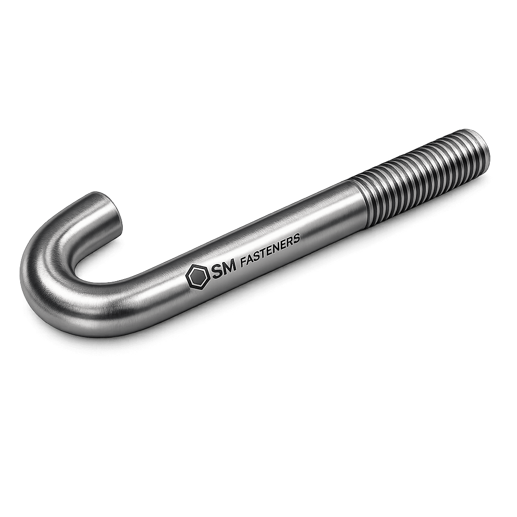
J Bolt
1. Industry Context
1.1 Role of J Bolts in Industrial Fastening Systems
J Bolts are embedded anchoring fasteners designed to transfer structural, mechanical, and dynamic loads between equipment or structural components and concrete or foundation substrates.

Unlike conventional bolting systems that rely purely on threaded engagement, J Bolts create mechanical anchorage through geometric interlock within concrete mass.
They are widely deployed across heavy engineering sectors where:
- Structural stability
- Vibration resistance
- Long-term load retention
- Installation reliability
- Foundation anchoring integrity
are critical engineering requirements.
1.2 Industrial Sectors Utilizing J Bolts
| Industry Sector | Functional Purpose |
|---|---|
| Structural Steel Construction | Column base plate anchoring |
| Oil & Gas Facilities | Equipment skid mounting |
| Power Generation | Turbine & generator foundations |
| Petrochemical Plants | Pipe racks & heavy equipment |
| Offshore Platforms | Deck equipment anchorage |
| Rail & Infrastructure | Signaling poles & bridge elements |
| Shipbuilding | Machinery seating |
| Automotive Manufacturing | Production line equipment mounting |
| Renewable Energy | Solar structures & wind tower bases |
J Bolts remain preferred where cast-in-place anchoring provides superior reliability compared to post-installed anchors.
1.3 Position of SM Fasteners in Industrial Supply
SM Fasteners manufactures J Bolts under:
- ISO 9001 certified quality systems
- Full traceability manufacturing
- International standards compliance
- Advanced material capability including:
- Stainless steels
- Alloy steels
- Duplex & Super Duplex
- Nickel alloys
- SMO 254
- High-performance polymers such as PEEK fasteners
Production supports EPC contractors, OEM manufacturers, and global infrastructure projects requiring audit-ready documentation.
2. Technical Definition of J Bolt
2.1 Engineering Definition
A J Bolt is a bent anchor bolt featuring:
- A threaded straight shank
- A curved hook resembling the letter “J”
- Load transfer through embedment and bearing resistance within concrete.
The hook generates resistance against:
- Pull-out forces
- Uplift loads
- Shear displacement
- Dynamic vibration effects
2.2 Fundamental Components
| Component | Function |
|---|---|
| Threaded Portion | Accepts nut and washer assembly |
| Straight Shank | Transfers axial stress |
| Curved Hook | Mechanical anchorage in concrete |
| Embedment Length | Determines pull-out capacity |
| Bearing Zone | Distributes load to surrounding concrete |
2.3 Difference from Other Anchor Systems
| Fastener Type | Load Mechanism | Installation |
|---|---|---|
| J Bolt | Mechanical embedment | Cast-in-place |
| L Bolt | Bearing + friction | Cast-in-place |
| Straight Anchor | Bond adhesion | Chemical anchor |
| Expansion Anchor | Radial expansion | Post-installed |
| Stud Anchor | Head bearing | Cast-in-place |
J Bolts are selected when simple geometry with dependable anchorage is required without complex fabrication.
3. Functional Role in Joint Design
J Bolts form part of a foundation anchoring system comprising:
- Concrete mass
- Base plate
- Washer system
- Nut assembly
- Embedded anchor
The assembly converts equipment loads into distributed stresses within concrete.
3.1 Primary Engineering Functions
- Resists tensile uplift loads
- Prevents equipment overturning
- Transfers shear forces
- Maintains alignment under vibration
- Controls fatigue movement
3.2 Typical Joint Arrangement
Equipment Load
      ↓
Base Plate
      ↓
Nut + Washer
      ↓
Threaded J Bolt
      ↓
Embedded Hook
      ↓
Concrete Foundation
4. Load Mechanics & Force Behavior
Understanding J Bolt performance requires evaluation of combined loading conditions.
4.1 Types of Loads Acting on J Bolts
| Load Type | Description |
|---|---|
| Tensile Load | Uplift or pull-out force |
| Shear Load | Horizontal sliding |
| Combined Load | Simultaneous tension + shear |
| Dynamic Load | Rotating equipment vibration |
| Impact Load | Sudden force application |
| Fatigue Load | Cyclic stress variation |
4.2 Tensile Load Transfer Mechanism
Resistance is generated through:
- Hook bearing against concrete
- Concrete cone resistance
- Friction along embedment length
Pull-out capacity depends primarily on:
- Embedment depth
- Concrete strength
- Bolt diameter
- Edge distance
- Reinforcement interaction
4.3 Concrete Failure Cone Concept
When tension load increases, concrete tends to fail in a conical fracture pattern.
Typical cone angle ≈ 35°–45° from vertical axis.
Design must ensure:
Failure should occur in steel rather than concrete whenever possible.
4.4 Shear Load Behavior
Shear loads are resisted by:
- Bolt shear strength
- Concrete bearing resistance
- Base plate friction
- Washer confinement
Engineering design checks include:
- Single shear
- Double shear
- Edge breakout resistance
4.5 Combined Tension and Shear Interaction
Design condition:
Where:
- = applied shear
- = applied tension
Used in ACI 318 and international anchoring standards.
4.6 Preload and Clamping Mechanics
Although embedded anchors primarily resist load via embedment, correct tightening produces:
- Joint stability
- Vibration resistance
- Load sharing across anchors
Preload is generated by tightening torque.
Torque–Preload Relationship
Where:
- T = Torque
- K = Nut factor (friction coefficient)
- F = Preload force
- d = Nominal diameter
Typical nut factor:
| Condition | Nut Factor (K) |
|---|---|
| Dry | 0.20–0.25 |
| Lubricated | 0.15–0.18 |
| PTFE coated | 0.10–0.13 |
4.7 Load Path Engineering
A properly designed J Bolt ensures:
- Load enters bolt threads.
- Axial force transfers through shank.
- Hook converts tension into bearing.
- Concrete distributes load volumetrically.
4.8 Friction & Thread Engagement
Minimum thread engagement:
| Bolt Diameter | Minimum Engagement |
|---|---|
| ≤ M16 | 1 × Diameter |
| M20–M30 | 1.25 × Diameter |
| ≥ M36 | 1.5 × Diameter |
Insufficient engagement leads to:
- Thread stripping
- Nut failure
- Loss of preload
5. Joint Design Principles
5.1 Design Objectives
Engineering design must achieve:
- Steel yielding before concrete failure
- Uniform load distribution
- Prevention of eccentric loading
- Resistance to fatigue
5.2 Critical Design Parameters
| Parameter | Engineering Importance |
|---|---|
| Embedment Depth | Controls pull-out capacity |
| Edge Distance | Prevents concrete breakout |
| Bolt Spacing | Load interaction control |
| Concrete Grade | Governs bearing strength |
| Washer Size | Load distribution |
| Anchor Layout | Stability of base plate |
5.3 Embedment Depth Guidelines
Typical embedment recommendations:
| Bolt Size | Recommended Embedment |
|---|---|
| M12 | 150–200 mm |
| M16 | 200–250 mm |
| M20 | 250–350 mm |
| M24 | 300–450 mm |
| M30 | 400–600 mm |
| M36 | 500–700 mm |
Actual values determined through structural calculation.
5.4 Edge Distance Requirements
Minimum edge distance:
Prevents:
- Concrete cracking
- Edge breakout failure
5.5 Anchor Group Behavior
Multiple J Bolts act as a system.
Design considerations include:
- Load redistribution
- Plate stiffness
- Anchor eccentricity
- Group reduction factors
5.6 Fatigue Design Considerations
Important for:
- Rotating machinery
- Compressors
- Pumps
- Turbines
Fatigue resistance depends on:
- Controlled preload
- Surface finish
- Proper heat treatment
- Thread rolling quality
5.7 Failure Mechanisms (Overview)
| Failure Mode | Cause |
|---|---|
| Steel Tensile Failure | Overload |
| Concrete Cone Failure | Insufficient embedment |
| Shear Failure | Lateral load |
| Thread Stripping | Low engagement |
| Fatigue Failure | Cyclic loading |
| Corrosion Failure | Environmental attack |
Detailed failure analysis appears in later sections.
5.8 Design Codes Referenced
Engineering design commonly references:
- ACI 318 — Concrete Anchoring
- EN 1992-4 — Fastenings to Concrete
- ASTM F1554 — Anchor Bolt Specification
- ISO 898-1 — Mechanical Properties
- BS 8539 — Post-installed Anchors Guidance
6. Engineering Selection Overview
Before specifying a J Bolt, engineers must evaluate:
- Applied loads
- Concrete strength
- Environmental exposure
- Temperature range
- Corrosion risk
- Installation sequence
- Inspection requirements
SM Fasteners supports project-specific engineering with custom geometry manufacturing aligned to international standards and EPC project specifications.
7. Product Types and Variants
J Bolts are engineered in multiple configurations to meet structural, mechanical, and foundation anchoring requirements across EPC and heavy engineering industries.
Selection depends on:
- Load magnitude
- Concrete embedment conditions
- Installation method
- Environmental exposure
- Applicable international standards
7.1 Standard J Bolt Configuration
Primary Characteristics
- One end threaded
- Opposite end formed into curved hook
- Cast directly into concrete
- Supplied with nuts and washers
Typical applications:
- Structural columns
- Pipe supports
- Equipment foundations
- Tank anchoring
7.2 Long Pattern J Bolt
Designed for:
- Deep embedment
- High uplift loads
- Heavy rotating equipment
Features:
- Extended shank length
- Increased concrete engagement
- Reduced pull-out probability
Used in:
- Turbine foundations
- LNG modules
- Offshore structures
7.3 Heavy Duty J Bolt
Manufactured from higher-strength material grades.
Characteristics:
- Large diameter
- High proof load capacity
- Increased bend radius
- Enhanced fatigue resistance
Common in:
- Petrochemical reactors
- Power plant installations
- Mining equipment
7.4 Fully Threaded J Bolt
Threading extended near bend region.
Advantages:
- Adjustable height positioning
- Flexible installation tolerance
Limitations:
- Requires controlled stress analysis near bend area.
7.5 Double Nut J Bolt Assembly
Includes:
- Leveling nut
- Locking nut
- Hardened washers
Provides:
- Alignment adjustment
- Enhanced vibration resistance
7.6 Custom Engineered J Bolts — SM Fasteners Capability
SM Fasteners manufactures project-specific anchors including:
- Non-standard hook geometry
- Extended threading
- Multi-bend anchors
- Sleeve-integrated anchors
- High-temperature alloy versions
- PEEK coated or polymer isolation systems
Custom production supported by:
- ISO 9001 design verification
- Drawing approval workflow
- Traceable batch manufacturing
8. Dimensional Logic & Geometry Engineering
J Bolt geometry directly influences mechanical performance.
8.1 Critical Geometrical Parameters
| Parameter | Symbol | Engineering Function |
|---|---|---|
| Bolt Diameter | d | Load capacity |
| Thread Length | b | Nut engagement |
| Embedment Length | hef | Pull-out resistance |
| Hook Radius | R | Stress distribution |
| Overall Length | L | Installation geometry |
| Thread Pitch | P | Load transfer efficiency |
8.2 Hook Geometry Engineering
Improper bending introduces stress concentration.
Recommended bend radius:
Benefits:
- Prevents cracking
- Maintains metallurgical integrity
- Improves fatigue life
SM Fasteners controls bending through calibrated forming dies to ensure dimensional repeatability.
8.3 Dimensional Specification Table (Metric Series)
| Size | Thread Pitch | Thread Length (mm) | Hook Radius (mm) | Standard Embedment (mm) | Overall Length Range |
|---|---|---|---|---|---|
| M12 | 1.75 | 50 | 36 | 150 | 200–300 |
| M16 | 2.0 | 65 | 48 | 200 | 250–400 |
| M20 | 2.5 | 80 | 60 | 250 | 300–500 |
| M24 | 3.0 | 90 | 72 | 300 | 400–600 |
| M30 | 3.5 | 110 | 90 | 400 | 500–800 |
| M36 | 4.0 | 130 | 108 | 500 | 650–1000 |
| M42 | 4.5 | 150 | 126 | 600 | 800–1200 |
Dimensions adjustable based on EPC drawings.
8.4 Imperial Size Reference (UNC/UNF)
| Nominal Size | Thread Type | Pitch (TPI) | Typical Embedment |
|---|---|---|---|
| 1/2″ | UNC | 13 | 6–8 in |
| 5/8″ | UNC | 11 | 8–10 in |
| 3/4″ | UNC | 10 | 10–12 in |
| 1″ | UNC | 8 | 12–16 in |
| 1-1/4″ | UNC | 7 | 16–20 in |
| 1-1/2″ | UNC | 6 | 18–24 in |
9. Applicable International Standards
J Bolt manufacturing and specification follow globally accepted fastener and anchoring standards.
9.1 ASTM Standards
| Standard | Scope |
|---|---|
| ASTM F1554 | Anchor bolts for structural applications |
| ASTM A307 | Carbon steel bolts |
| ASTM A193 | Alloy steel bolting for high temperature |
| ASTM A320 | Low-temperature bolting |
| ASTM F436 | Hardened washers |
| ASTM A194 | Nuts for high-pressure service |
ASTM F1554 Grades:
| Grade | Yield Strength |
|---|---|
| Grade 36 | 248 MPa |
| Grade 55 | 379 MPa |
| Grade 105 | 724 MPa |
9.2 ISO Standards
| ISO Standard | Description |
|---|---|
| ISO 898-1 | Mechanical properties of fasteners |
| ISO 965 | Thread tolerances |
| ISO 4014/4017 | Metric bolt dimensions |
| ISO 3506 | Stainless steel fasteners |
| ISO 3269 | Acceptance inspection |
9.3 DIN Standards
| DIN Standard | Application |
|---|---|
| DIN 529 | Foundation bolts |
| DIN 976 | Threaded rods |
| DIN 267 | Fastener property classes |
9.4 British Standards (BS)
| Standard | Description |
|---|---|
| BS 4190 | Metric fasteners |
| BS 3692 | Precision threads |
| BS EN 1992-4 | Concrete anchor design |
| BS 7419 | Holding down bolts |
10. Property Class Systems
Mechanical strength classification varies between ISO and ASTM systems.
10.1 ISO Property Classes
| Property Class | Yield Strength (MPa) | UTS (MPa) | Typical Application |
|---|---|---|---|
| 4.6 | 240 | 400 | Light anchoring |
| 5.8 | 400 | 500 | Structural fixing |
| 8.8 | 640 | 800 | Industrial equipment |
| 10.9 | 940 | 1040 | Heavy machinery |
| 12.9 | 1100 | 1220 | High-stress assemblies |
10.2 ASTM vs ISO Comparison
| ASTM Grade | Approx ISO Equivalent |
|---|---|
| A307 | 4.6 |
| F1554 Gr 36 | 4.6 |
| F1554 Gr 55 | 5.8–8.8 |
| F1554 Gr 105 | 10.9 |
11. Thread Standards & Tolerances
Thread compatibility is critical for procurement interoperability.
11.1 Thread System Comparison
| Thread System | Region | Profile Angle |
|---|---|---|
| Metric ISO | Global | 60° |
| UNC | USA | 60° |
| UNF | USA | 60° |
| BSW | UK | 55° |
| BSF | UK | 55° |
11.2 Tolerance Classes
| Thread Type | External Thread | Internal Thread |
|---|---|---|
| Metric Standard | 6g | 6H |
| Precision | 4g6g | 5H |
| Structural | 8g | 7H |
SM Fasteners verifies threads using calibrated GO/NO-GO gauges aligned with ISO 965.
12. Dimensional Interchangeability
Engineering projects often involve multi-standard environments.
Interchangeability considerations:
- Metric ↔ Imperial conversion
- Property class equivalence
- Washer hardness compatibility
- Nut proof load matching
Incorrect interchangeability may result in:
- Loss of preload
- Thread galling
- Joint failure
13. Mechanical Property Reference Table
| Grade | Yield Strength (MPa) | Tensile Strength (MPa) | Hardness (HB) |
|---|---|---|---|
| F1554 Gr 36 | 248 | 400 | 120–170 |
| F1554 Gr 55 | 379 | 517 | 150–200 |
| 8.8 | 640 | 800 | 250–320 |
| 10.9 | 940 | 1040 | 320–380 |
| B7 | 720 | 860 | 248–302 |
| Stainless A4-70 | 450 | 700 | ≤ 215 |
14. Weight Chart — J Bolts
(Aligned with SM Fasteners Manufacturing Data)
Approximate weights based on carbon steel density.
| Size | Length (mm) | Weight / Piece (kg) | Weight / 100 pcs (kg) |
|---|---|---|---|
| M12 × 250 | 0.22 | 22 | |
| M16 × 300 | 0.45 | 45 | |
| M20 × 350 | 0.78 | 78 | |
| M24 × 450 | 1.40 | 140 | |
| M30 × 600 | 2.85 | 285 | |
| M36 × 750 | 5.10 | 510 | |
| M42 × 900 | 8.20 | 820 |
Used for:
- Logistics planning
- Export packing calculations
- Crane load estimation
15. Engineering Selection Logic Summary
Correct J Bolt selection requires alignment of:
- Geometry
- Mechanical grade
- Material compatibility
- Thread system
- Installation conditions
- International compliance requirements
SM Fasteners provides drawing-based manufacturing ensuring dimensional conformity and standards traceability required by EPC procurement and third-party inspection bodies.
16. Material Grades & Selection Criteria
Material selection for J Bolts is governed by:
- Applied mechanical load
- Service temperature
- Corrosive environment
- Design life requirement
- Compliance with project specifications (EPC/Owner standards)
- NACE / sour service requirements (where applicable)
SM Fasteners manufactures J Bolts across a full industrial material spectrum under controlled ISO 9001 quality systems.
16.1 Carbon Steel Grades
Primarily used for structural and general anchoring.
| Standard | Grade | Yield (MPa) | UTS (MPa) | Temp Range | Typical Application |
|---|---|---|---|---|---|
| ASTM F1554 | Gr 36 | 248 | 400 | -20°C to 200°C | Structural columns |
| ASTM F1554 | Gr 55 | 379 | 517 | -20°C to 200°C | Equipment anchoring |
| ASTM F1554 | Gr 105 | 724 | 862 | -20°C to 200°C | Heavy machinery |
| ASTM A307 | Gr A | 207 | 414 | Ambient | Light anchoring |
Advantages:
- Cost effective
- Good machinability
- Suitable for non-corrosive environments
Limitations:
- Requires protective coating
- Susceptible to corrosion
16.2 Alloy Steel Grades
Used where higher strength or temperature resistance is required.
| Standard | Grade | Yield (MPa) | UTS (MPa) | Temp Range | Application |
|---|---|---|---|---|---|
| ASTM A193 | B7 | 720 | 860 | -29°C to 450°C | Petrochemical |
| ASTM A320 | L7 | 690 | 830 | -101°C to 450°C | Low temperature |
| ASTM A193 | B16 | 760 | 860 | Up to 540°C | High temp service |
Applications:
- Refineries
- Pressure equipment
- LNG installations
- Power plants
16.3 Stainless Steel Grades
Used in corrosive or hygienic environments.
| Grade | Yield (MPa) | UTS (MPa) | Corrosion Resistance | Typical Industry |
|---|---|---|---|---|
| SS304 (A2) | 215 | 515 | Moderate | Construction |
| SS316 (A4) | 205 | 515 | Marine grade | Coastal |
| A4-70 | 450 | 700 | High | Chemical |
| A4-80 | 600 | 800 | High | Offshore |
Advantages:
- Corrosion resistance
- Low maintenance
- Suitable for marine exposure
16.4 Duplex & Super Duplex
Used in aggressive chloride environments.
| Grade | Yield (MPa) | UTS (MPa) | PREN | Application |
|---|---|---|---|---|
| Duplex 2205 | 450 | 620 | 35 | Offshore |
| Super Duplex 2507 | 550 | 795 | 42+ | Subsea |
16.5 Nickel Alloys & Special Grades
| Material | Temp Limit | Corrosion Performance | Industry |
|---|---|---|---|
| Inconel 625 | 980°C | Excellent | Power, Offshore |
| Incoloy 825 | 540°C | Acid resistant | Chemical |
| Monel 400 | 480°C | Seawater resistant | Marine |
| Hastelloy C276 | 1040°C | Extreme corrosion | Refinery |
| SMO 254 | 300°C | High chloride resistance | Desalination |
16.6 High Performance Polymer — PEEK j bolt
SM Fasteners supplies PEEK-based anchoring systems for:
- Electrical insulation
- Chemical exposure
- Non-magnetic environments
- Weight reduction applications
Properties:
| Property | Value |
|---|---|
| Tensile Strength | ~90–100 MPa |
| Temp Limit | 250–260°C |
| Chemical Resistance | Excellent |
| Electrical Insulation | High |
Applications:
- Semiconductor plants
- Chemical processing
- Electrical infrastructure
17. Corrosion Resistance vs Environment Table
| Environment | Carbon Steel (Galv) | SS316 | Duplex 2205 | Inconel 625 | PEEK |
|---|---|---|---|---|---|
| Marine | Moderate | Good | Excellent | Excellent | Excellent |
| H₂S (Sour) | Limited | Moderate | Good | Excellent | Excellent |
| Acidic | Poor | Moderate | Good | Excellent | Excellent |
| LNG | Good | Good | Excellent | Excellent | Good |
| Offshore Splash Zone | Poor | Moderate | Excellent | Excellent | Good |
| High Temperature | Limited | Moderate | Good | Excellent | Moderate |
18. Heat Treatment Processes
Heat treatment directly impacts mechanical properties.
18.1 Carbon & Alloy Steel Heat Treatment
| Process | Purpose |
|---|---|
| Normalizing | Grain refinement |
| Quenching | Increase hardness |
| Tempering | Reduce brittleness |
| Stress Relieving | Remove residual stresses |
Example — ASTM A193 B7:
- Austenitize at ~870°C
- Oil quench
- Temper at 425–650°C
Results:
- Controlled hardness
- Improved fatigue strength
- Stable microstructure
18.2 Hardness Limits (Sour Service)
For NACE MR0175 compliance:
- Maximum hardness: 22 HRC (approx. 237 HB) for certain grades
- Prevents sulfide stress cracking
SM Fasteners ensures hardness verification through calibrated testing.
18.3 Stainless Steel Processing
- Solution annealing
- Passivation
- Pickling
- Controlled cooling
Ensures corrosion resistance and prevents sensitization.
19. End-to-End Manufacturing Workflow
SM Fasteners follows documented ISO 9001 production control procedures.
19.1 Raw Material Verification
- Mill Test Certificate (EN 10204 3.1)
- Chemical composition verification
- Spectrometer / PMI testing
- Heat number traceability
19.2 Cutting & Preparation
- CNC saw cutting
- Length tolerance control
- Heat number stamping
19.3 Forming Process
Hot Forging (Large Sizes)
- Controlled heating
- Hydraulic press forming
- Die-controlled bending
Cold Bending (Smaller Sizes)
- CNC bending machine
- Controlled bend radius
- Crack prevention monitoring
19.4 Thread Manufacturing
| Method | Advantage |
|---|---|
| Thread Rolling | Increased fatigue strength |
| Thread Cutting | Suitable for large/custom sizes |
Thread rolling preferred for structural applications due to:
- Grain flow continuity
- Improved surface finish
- Higher fatigue resistance
19.5 Heat Treatment (If Required)
Performed in:
- Controlled atmosphere furnaces
- Temperature monitored cycles
- Hardness verification post-treatment
19.6 Straightness & Geometry Inspection
Checks include:
- Overall length
- Hook radius
- Thread gauge test
- Concentricity verification
20. Surface Finishing & Coating Systems
Surface engineering enhances durability and corrosion resistance.
20.1 Surface Finish Comparison
| Coating Type | Corrosion Protection | Temp Limit | Thickness | Application |
|---|---|---|---|---|
| Black Oxide | Low | 120°C | Minimal | Indoor |
| Zinc Plated | Moderate | 200°C | 8–12 µm | General |
| Hot Dip Galvanized | High | 450°C | 45–85 µm | Structural |
| PTFE Coated | Chemical resistant | 260°C | Variable | Petrochemical |
| Dacromet | High | 300°C | 5–15 µm | Marine |
| Epoxy Coating | High | 150°C | 80–150 µm | Water treatment |
| Mechanical Galv | Moderate | 200°C | 15–25 µm | Structural |
| Passivation (SS) | Enhances corrosion resistance | — | — | Stainless |
20.2 Hydrogen Embrittlement Considerations
High strength bolts (> 1000 MPa):
- Avoid electroplating without baking
- Require hydrogen relief bake within 4 hours
SM Fasteners follows controlled baking cycles where applicable.
20.3 Surface Preparation Prior to Coating
- Degreasing
- Shot blasting
- Pickling
- Phosphating (if required)
21. Failure Mechanisms — Detailed Engineering View
21.1 Fatigue Failure
Caused by:
- Cyclic loading
- Surface imperfections
- Poor preload control
Mitigation:
- Thread rolling
- Proper torque application
- Smooth surface finish
21.2 Shear Failure
Occurs under:
- Lateral loads
- Insufficient bolt diameter
Prevented by:
- Adequate sizing
- Load distribution plate design
21.3 Hydrogen Embrittlement
Risk in:
- High-strength carbon/alloy steel
- Electroplated components
Control through:
22. Material Selection Logic Summary
Selection must balance:
- Mechanical strength
- Environmental durability
- Temperature resistance
- Cost efficiency
- Code compliance
- Inspection requirement
SM Fasteners provides:
- Multi-material manufacturing capability
- Custom geometry production
- Heat treatment control
- Coating flexibility
- Full traceability
23. Inspection & Quality Control System
J Bolts used in structural and industrial foundations are classified as critical load-bearing components.
Inspection requirements therefore extend beyond dimensional verification to include mechanical integrity, metallurgy, and traceability.
SM Fasteners integrates inspection controls within an ISO 9001 certified manufacturing framework aligned with EPC and third-party inspection practices.
23.1 Incoming Material Inspection
Verification performed prior to production:
| Inspection Activity | Method | Purpose |
|---|---|---|
| Mill Test Certificate Review | EN 10204 3.1 | Material conformity |
| Chemical Composition | Optical Spectrometer / PMI | Grade verification |
| Heat Number Traceability | Marking verification | Full traceability |
| Visual Examination | Surface check | Defect detection |
| Ultrasonic Test (Large Dia) | UT | Internal flaw detection |
23.2 In-Process Inspection
| Stage | Inspection |
|---|---|
| Cutting | Length tolerance |
| Bending | Hook radius verification |
| Threading | GO/NO-GO gauge inspection |
| Heat Treatment | Hardness monitoring |
| Coating | Thickness measurement |
23.3 Final Inspection
| Test | Standard Reference |
|---|---|
| Dimensional Inspection | ISO 3269 |
| Tensile Testing | ASTM A370 |
| Proof Load Test | ISO 898-1 |
| Hardness Test | ASTM E18 |
| Coating Thickness | ASTM B499 |
| Visual Examination | ISO 6157 |
| PMI Testing | Project Requirement |
23.4 Non-Destructive Testing (NDT)
Applied for critical EPC applications.
| Method | Purpose |
|---|---|
| Magnetic Particle Testing (MPI) | Surface cracks |
| Ultrasonic Testing (UT) | Internal defects |
| Dye Penetrant (DPT) | Surface discontinuities |
| Radiography (RT) | Specialized requirements |
23.5 Certification & Documentation
SM Fasteners supplies:
- EN 10204 3.1 / 3.2 MTC
- Heat treatment reports
- Coating reports
- Dimensional inspection records
- Third-party inspection certification
- Certificate of Conformance (CoC)
24. Mechanical Properties — Grade Wise Table
| Grade | Yield Strength (MPa) | Tensile Strength (MPa) | Proof Load (MPa) | Hardness |
|---|---|---|---|---|
| F1554 Gr 36 | 248 | 400 | 220 | 120–170 HB |
| F1554 Gr 55 | 379 | 517 | 310 | 150–200 HB |
| F1554 Gr 105 | 724 | 862 | 620 | 235–300 HB |
| ISO 8.8 | 640 | 800 | 580 | 250–320 HB |
| ISO 10.9 | 940 | 1040 | 830 | 320–380 HB |
| ASTM B7 | 720 | 860 | 600 | 248–302 HB |
| A4-80 SS | 600 | 800 | 600 | ≤ 300 HB |
25. Proof Load & Tensile Capacity Table (Typical)
| Size | Tensile Area (mm²) | Proof Load 8.8 (kN) | Ultimate Load (kN) |
|---|---|---|---|
| M12 | 84 | 49 | 67 |
| M16 | 157 | 91 | 126 |
| M20 | 245 | 142 | 196 |
| M24 | 353 | 205 | 282 |
| M30 | 561 | 325 | 448 |
| M36 | 817 | 474 | 653 |
| M42 | 1120 | 650 | 896 |
Values used for engineering estimation; project calculations must verify embedment design.
26. Tightening Torque Chart
Torque values assume standard nut factor conditions.
| Size | Grade | Dry Torque (Nm) | Lubricated Torque (Nm) |
|---|---|---|---|
| M12 | 8.8 | 85 | 65 |
| M16 | 8.8 | 210 | 160 |
| M20 | 8.8 | 410 | 310 |
| M24 | 8.8 | 710 | 540 |
| M30 | 8.8 | 1400 | 1050 |
| M36 | 8.8 | 2450 | 1850 |
Proper torque ensures preload without overstressing anchor.
27. Preload Calculation
Governing Equation
Where:
- F = Preload Force (N)
- T = Applied Torque (Nm)
- K = Nut factor
- d = Bolt diameter (m)
Worked Engineering Example
Given:
- Bolt: M24
- Torque: 540 Nm (lubricated)
- Nut Factor: 0.16
- Diameter: 0.024 m
Result:
✔ Correct preload achieved for Grade 8.8 anchor.
28. Thread Standards & Tolerances Table
| Thread Type | Standard | Tolerance Class | Application |
|---|---|---|---|
| Metric Coarse | ISO 261 | 6g/6H | Global structural |
| Metric Fine | ISO 261 | 4g6g | Precision |
| UNC | ASME B1.1 | 2A/2B | USA equipment |
| UNF | ASME B1.1 | 2A/2B | Vibration resistance |
| BSW | BS 84 | Medium fit | Legacy systems |
| BSF | BS 84 | Close fit | Mechanical equipment |
SM Fasteners verifies threads using calibrated gauges.
29. Surface Finish Performance Comparison
| Coating | Salt Spray Resistance | Abrasion Resistance | Typical Life |
|---|---|---|---|
| Zinc Plating | 72–120 hrs | Moderate | Indoor |
| Hot Dip Galvanized | 500+ hrs | High | Structural outdoor |
| PTFE | Excellent | Medium | Chemical plants |
| Dacromet | 1000 hrs | High | Marine |
| Epoxy | Excellent | Medium | Water systems |
| Passivation (SS) | Excellent | High | Offshore |
30. Weight Chart — J Bolts
(SM Fasteners Manufacturing Reference)
| Size | Length | Weight/Piece (kg) | Weight/100 pcs (kg) |
|---|---|---|---|
| M12×250 | 0.22 | 22 | |
| M16×300 | 0.45 | 45 | |
| M20×350 | 0.78 | 78 | |
| M24×450 | 1.40 | 140 | |
| M30×600 | 2.85 | 285 | |
| M36×750 | 5.10 | 510 | |
| M42×900 | 8.20 | 820 |
Used for export logistics planning and lifting calculations.
31. Industry Applications
31.1 Construction & Structural Steel
- Column base plates
- Steel frame anchoring
- Bridge infrastructure
- Pre-engineered buildings
31.2 Oil & Gas Industry
Upstream
- Drilling equipment
- Skid mounting
Midstream
- Pump stations
- Compressor foundations
Downstream
- Refinery equipment
- Pipe racks
Materials frequently supplied:
- ASTM A193 B7
- Duplex 2205
- NACE compliant grades
31.3 Power Generation
- Turbine bases
- Boiler structures
- Generator anchoring
- Wind energy towers
High fatigue resistance required.
31.4 Petrochemical & Chemical Plants
- Reactor anchoring
- Storage tank foundations
- Acid-resistant installations
Preferred materials:
- SS316
- Hastelloy
- Inconel
- PTFE coated J Bolts
31.5 LNG & Offshore Installations
Requirements:
- Low temperature toughness
- Chloride resistance
- Long service life
Typical materials:
- ASTM A320 L7
- Super Duplex
- Nickel alloys
31.6 Railways & Infrastructure
- Signaling structures
- Gantry mounting
- Electrification poles
31.7 Automotive & Heavy Equipment
- Assembly lines
- Press machines
- Robotic platforms
31.8 Shipbuilding & Marine
- Engine mounting
- Deck equipment anchoring
- Marine structural fastening
31.9 PEEK Fastener Applications
Where metallic fasteners are unsuitable:
- Electrical isolation
- Chemical exposure zones
- MRI/non-magnetic equipment
- Semiconductor facilities
32. Failure Prevention Engineering
| Failure Mode | Prevention Strategy |
|---|---|
| Concrete breakout | Proper embedment |
| Fatigue cracking | Controlled preload |
| Corrosion | Material upgrade/coating |
| Thread stripping | Correct engagement |
| Hydrogen embrittlement | Baking + hardness control |
| Stress corrosion | Duplex/Nickel alloys |
33. Export Packaging & Logistics
SM Fasteners prepares J Bolts for global shipment using industrial packaging protocols.
33.1 Industrial Packaging
- VCI corrosion protection
- Thread caps
- Bundled anchor sets
- Heat number tagging
- Moisture barrier wrapping
33.2 Export Crating
- ISPM-15 compliant wooden crates
- Steel pallet packaging
- Containerized shipment planning
- Weight-balanced packing
33.3 Identification & Traceability
Each batch marked with:
- Heat number
- Grade
- Size
- SM Fasteners identification
34. Export Documentation Package
Supplied with every project shipment:
- Mill Test Certificate (EN 10204 3.1 / 3.2)
- Dimensional inspection report
- Mechanical test report
- Heat treatment chart
- Coating certification
- Packing list
- Certificate of Origin
- Certificate of Conformance
Supports EPC audits and international customs clearance.
35. Integration with ISO 9001 Quality Management
SM Fasteners manufacturing system ensures:
- Controlled procedures
- Documented inspections
- Calibration management
- Traceable production batches
- Corrective action tracking
- Continuous improvement compliance
Aligned with requirements of:
- EPC contractors
- Oil & Gas majors
- Power utilities
- Global OEM manufacturers
36. Engineering Procurement Advantages — SM Fasteners
SM Fasteners demonstrates:
✔ Multi-material manufacturing capability
✔ Custom engineered J Bolts
✔ Advanced alloys & PEEK fastener expertise
✔ International standards compliance (ISO / ASTM / DIN / BS)
✔ Full inspection traceability
✔ Export-ready logistics and documentation
✔ Reliable global supply capability