L Bolt
1. Industry Context
1.1 Role of L Bolts in Industrial Fastening Systems
The L Bolt (commonly referred to as an L-Type Anchor Bolt) is a permanently embedded fastening element designed to transfer structural loads between equipment, steel structures, and concrete foundations.
Unlike removable bolted joints, L bolts function as structural anchoring devices, forming an integral mechanical connection between:
- Structural steel columns
- Heavy rotating equipment
- Pipe racks and sleepers
- Transmission towers
- Industrial machinery bases
- Offshore modules
- Rail and infrastructure components
The geometry provides mechanical anchorage through embedment resistance, ensuring long-term load transfer under static and dynamic service conditions.
Within global EPC projects, L bolts are classified as:
- Foundation Fasteners
- Embedded Anchor Systems
- Structural Holding Down Bolts
They are critical safety components governed by strict engineering verification.
1.2 Industrial Importance
L bolts are specified in projects where failure consequences include:
- Structural instability
- Equipment misalignment
- Foundation cracking
- Fatigue propagation
- Catastrophic mechanical failure
Typical deployment sectors include:
| Industry | Function of L Bolt |
|---|---|
| Construction | Column base anchoring |
| Oil & Gas | Pump, compressor & skid mounting |
| Power Plants | Turbine foundation anchorage |
| Petrochemical | Pipe rack & vessel support |
| Offshore & LNG | Module fixation |
| Infrastructure | Bridge bearings & rail supports |
| Heavy Equipment | Dynamic machinery anchoring |
Because these bolts become non-replaceable after grouting, design and manufacturing accuracy are mandatory.
SM Fasteners manufactures L bolts aligned with international EPC specifications, supported by ISO 9001 certified quality systems, full material traceability, and project documentation readiness.
1.3 Functional Difference from Conventional Bolts
| Parameter | Standard Bolt | L Bolt |
|---|---|---|
| Installation | Removable | Embedded |
| Load Transfer | Clamp force | Concrete anchorage |
| Access Required | Both sides | Single side |
| Replacement | Possible | Generally impossible |
| Primary Load | Tension/Shear | Pull-out + Shear |
| Design Standard | Fastener codes | Structural anchorage codes |
2. Technical Definition
2.1 Engineering Definition
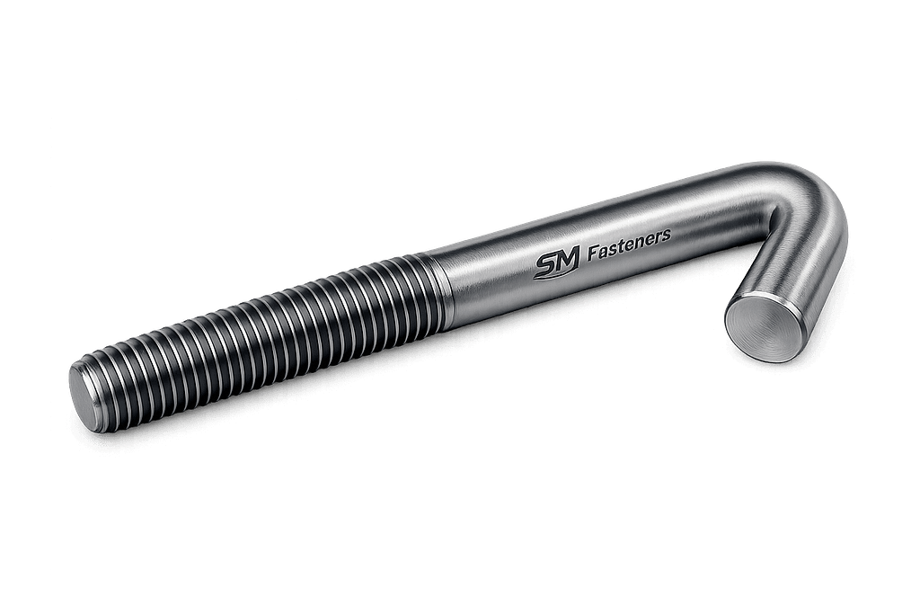
An L Bolt is a threaded rod bent at 90° forming an L-shape, installed into concrete to resist tensile, shear, and overturning forces through mechanical embedment and bond interaction.
Core Components
- Threaded Section
- Accepts nut and washer
- Provides preload capability
- Straight Shank
- Transfers tensile forces into concrete
- L Bend (Anchor Leg)
- Provides mechanical resistance against pull-out
- Embedment Length
- Critical design parameter governing load capacity
2.2 Geometry Terminology
| Term | Description |
|---|---|
| d | Nominal diameter |
| L | Overall length |
| Le | Embedment depth |
| Lb | Bend length |
| Lt | Thread length |
| R | Bend radius |
Correct proportioning directly affects anchorage strength.
2.3 Governing Design Standards
Although L bolts are custom-engineered, their design references multiple global codes:
- ACI 318 — Concrete anchorage design
- EN 1992-4 (Eurocode) — Fastenings to concrete
- ASTM F1554 — Anchor bolt specification
- ISO 898-1 — Mechanical properties
- DIN 529 — Foundation bolts
- BS 7419 — Holding down bolts
SM Fasteners supplies L bolts compliant with project-specific international standards.
3. Load Mechanics & Force Behavior
3.1 Load Types Acting on L Bolts
L bolts experience combined loading conditions:
1. Tensile Load (Primary)
Generated by:
- Wind uplift
- Equipment overturning
- Seismic forces
- Thermal expansion
2. Shear Load
Generated by:
- Lateral forces
- Equipment vibration
- Impact loading
3. Combined Tension + Shear
Most real-world installations operate under interaction loading.
3.2 Load Transfer Mechanism
Load transfer occurs through three mechanisms:
A. Mechanical Anchorage
The L-shaped bend prevents pull-out by bearing against concrete mass.
B. Bond Stress
Friction develops between bolt surface and cured concrete.
C. Bearing Resistance
Concrete compression resists movement around the anchor leg.
3.3 Simplified Pull-Out Resistance Concept
Ultimate tensile capacity depends on:
Where:
- = tensile stress area
- = yield strength
However, real anchorage strength is governed by:
- Concrete cone failure
- Steel yielding
- Bond failure
- Edge breakout
Design engineers must evaluate all modes.
3.4 Failure Modes in L Bolt Anchorage
| Failure Mode | Cause | Prevention |
|---|---|---|
| Steel Yielding | Undersized diameter | Proper grade selection |
| Pull-Out Failure | Insufficient embedment | Increase Le |
| Concrete Cone Failure | Edge distance violation | Design spacing |
| Shear Failure | Lateral overload | Shear lug or sleeves |
| Fatigue Failure | Cyclic loads | Preload control |
| Corrosion Failure | Aggressive environment | Material & coating selection |
3.5 Load Path in Structural Foundations
External Load
      ↓
Base Plate
      ↓
Nut & Washer
      ↓
Threaded Section
      ↓
Shank
      ↓
L Bend Anchorage
      ↓
Concrete Mass
      ↓
Ground
Every interface must remain structurally reliable for decades of service life.
4. Preload & Clamping Force Principles
4.1 Importance of Preload
Even though L bolts are embedded fasteners, controlled preload remains essential.
Preload ensures:
- Proper base plate seating
- Vibration resistance
- Load distribution among bolts
- Prevention of joint separation
4.2 Torque–Tension Relationship
Applied torque produces bolt tension.
Where:
- T = tightening torque
- K = nut factor (friction coefficient)
- F = preload force
- d = nominal diameter
Friction accounts for ~90% of applied torque losses.
4.3 Friction Components
| Location | Torque Consumption |
|---|---|
| Thread friction | 40–50% |
| Under-head friction | 40–50% |
| Useful preload | ~10% |
Surface condition therefore critically influences joint performance.
4.4 Nut Factor (K Value)
Typical values:
| Condition | Nut Factor K |
|---|---|
| Dry steel | 0.20–0.25 |
| Zinc plated | 0.18 |
| Lubricated | 0.12–0.15 |
| PTFE coated | 0.10 |
SM Fasteners controls surface finish and lubrication parameters to maintain predictable preload performance.
5. Joint Design Principles
5.1 Anchor Bolt Layout Engineering
Key parameters:
- Bolt circle diameter
- Edge distance
- Spacing
- Embedment depth
- Washer plate thickness
- Grout properties
Improper layout leads to premature concrete cracking.
5.2 Minimum Edge Distance Guidelines
| Bolt Diameter | Minimum Edge Distance |
|---|---|
| M16 | ≥ 120 mm |
| M20 | ≥ 150 mm |
| M24 | ≥ 180 mm |
| M30 | ≥ 225 mm |
| M36 | ≥ 270 mm |
(Actual values governed by ACI/Eurocode project design.)
5.3 Embedment Length Selection
Typical engineering rule:
Heavy dynamic machinery may require:
5.4 Thread Engagement Requirement
Minimum nut engagement:
High-strength grades:
Ensures full tensile capacity utilization.
5.5 Base Plate Interaction
Correct L bolt performance requires:
- Hardened washers
- Level grout bedding
- Controlled torque sequence
- Shim alignment
SM Fasteners provides custom-engineered L bolt assemblies including:
- Heavy hex nuts
- Double nut arrangements
- Plate washers
- Sleeves and templates
5.6 Dynamic Load Considerations
Applications involving vibration require:
- Higher preload ratios
- Locking systems
- Fatigue-rated materials
- Rolled threads
Typical dynamic industries:
- Compressors
- Turbines
- Crushers
- Marine propulsion equipment
5.7 Design Coordination with Civil Engineering
L bolts form the interface between mechanical and civil disciplines.
Coordination involves:
- Foundation drawing approval
- Bolt template manufacturing
- Position tolerance verification
- Pre-pour inspection
- Post-grout alignment validation
SM Fasteners supports EPC projects with fabrication-ready anchor bolt drawings and dimensional verification.
5.8 Long-Term Structural Reliability Factors
Service life depends on:
- Material compatibility
- Corrosion protection
- Stress distribution
- Installation accuracy
- Traceable manufacturing
Embedded fasteners must reliably perform for 20–50 year infrastructure lifecycles
6. Product Types and Variants
L Bolts are rarely standardized as off-the-shelf items. Instead, they are project-engineered anchoring components tailored to foundation design, loading conditions, and installation methodology.
SM Fasteners manufactures L bolts according to EPC drawings, international standards, and client specifications while maintaining dimensional interchangeability with global systems.
6.1 Primary L Bolt Configurations
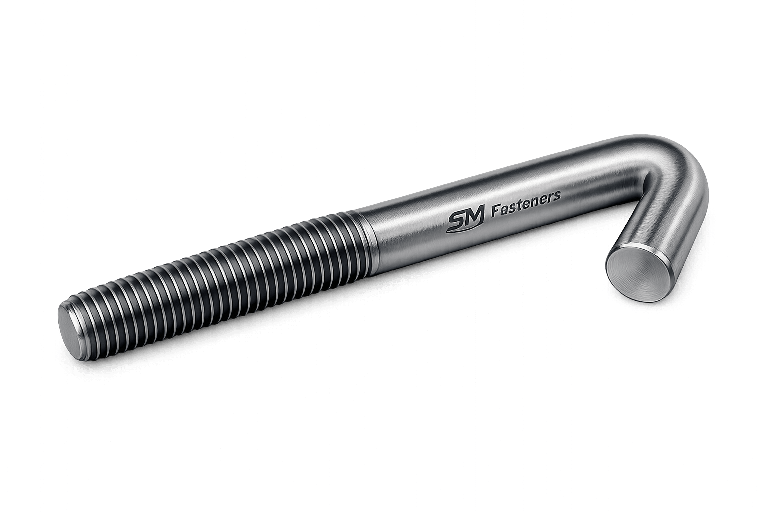
6.1.1 Standard L Type anchor bolt
Description
- Single 90° bend
- Threaded on one end
- Embedded in concrete foundation
Typical Use
- Structural columns
- Equipment bases
- Pipe supports
Characteristics
- Economical
- High tensile anchorage
- Widely accepted across EPC projects
6.1.2 Long Leg L Bolt (Deep Foundation Type)
Designed for heavy machinery and high uplift loads.
Features
- Increased embedment depth
- Improved pull-out resistance
- Reduced concrete cone failure risk
Applications:
- Gas turbines
- Refinery reactors
- Offshore modules
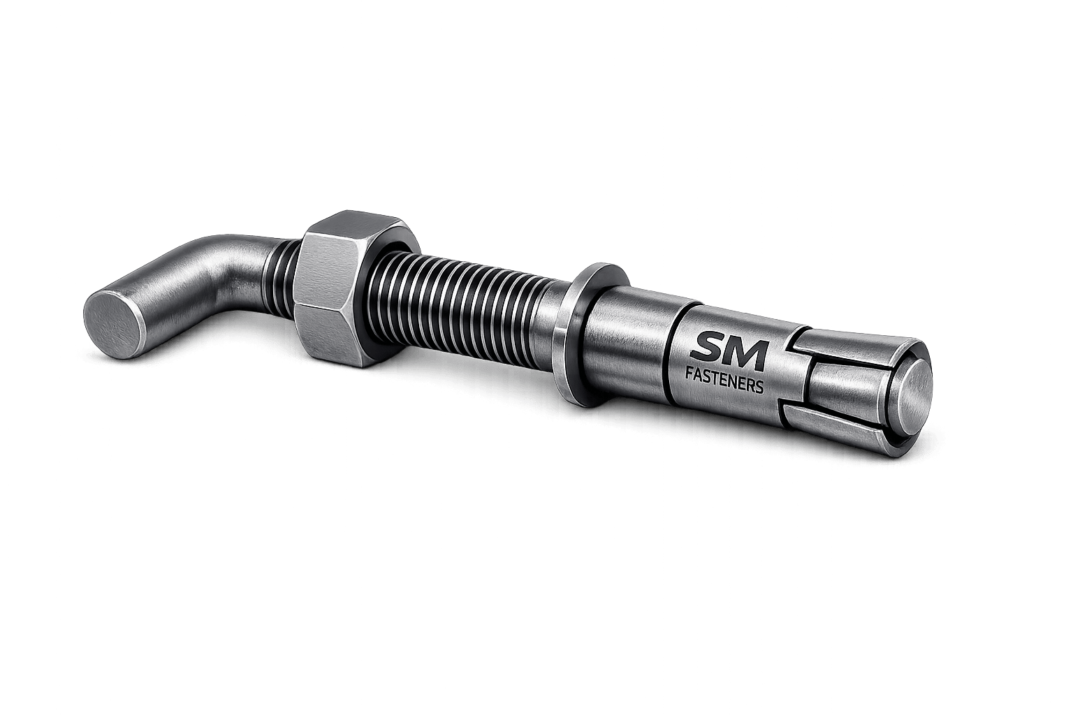
6.1.3 Sleeve Type L bolt
Includes protective sleeve over shank.
Purpose:
- Alignment adjustment during installation
- Compensation for foundation tolerances
Used in:
- Rotating equipment foundations
- Precision alignment installations
6.1.4 Double Nut L Bolt Assembly
Includes:
- Leveling nut
- Top tightening nut
- Heavy washer plate
Benefits:
- Precise elevation control
- Uniform load distribution
Common in:
- Steel structures
- EPC skid installations
6.1.5 Heavy Duty Forged L Bolt
Manufactured using hot forging rather than bending.
Advantages:
- Grain flow continuity
- Higher fatigue resistance
- Reduced stress concentration at bend
Recommended for:
- Offshore structures
- Seismic zones
- Dynamic loading environments
6.1.6 High Alloy & Corrosion Resistant L Bolts
Manufactured by SM Fasteners in advanced materials:
- Duplex Stainless Steel
- Super Duplex
- Inconel
- Hastelloy
- Monel
- SMO 254
- Nickel Alloys
- PEEK Fastener Hybrid Systems
Used in:
- LNG plants
- Chemical reactors
- Marine exposure
- Sour service environments
6.2 Functional Variant Comparison
| Variant | Load Capacity | Alignment Flexibility | Typical Industry |
|—|—|—|
| Standard L Bolt | Medium | Low | Construction |
| Long Leg Type | High | Low | Power & Petrochemical |
| Sleeve Type | Medium | High | Equipment Installation |
| Forged L Bolt | Very High | Medium | Offshore |
| Duplex Alloy L Bolt | High | Medium | Marine & LNG |
| PEEK Anchor System | Low–Medium | High | Electrical & Chemical |
7. Dimensional Logic & Geometry Engineering
7.1 Engineering Design Philosophy
L bolt geometry must balance:
- Steel strength
- Concrete capacity
- Installation practicality
- Load distribution
Improper geometry results in localized stress concentration or premature failure.
7.2 Key Dimensional Parameters
| Parameter | Symbol | Engineering Importance |
|---|---|---|
| Diameter | d | Governs tensile strength |
| Thread Length | Lt | Nut engagement |
| Embedment Length | Le | Pull-out resistance |
| Bend Length | Lb | Anchorage performance |
| Bend Radius | R | Fatigue resistance |
| Projection Height | Hp | Installation clearance |
7.3 Recommended Dimensional Proportions
| Bolt Size | Bend Length (Lb) | Min Embedment (Le) | Thread Length (Lt) |
|---|---|---|---|
| M12 | 60 mm | 150 mm | 40 mm |
| M16 | 80 mm | 200 mm | 50 mm |
| M20 | 100 mm | 250 mm | 60 mm |
| M24 | 120 mm | 300 mm | 75 mm |
| M30 | 150 mm | 375 mm | 90 mm |
| M36 | 180 mm | 450 mm | 110 mm |
| M42 | 210 mm | 525 mm | 125 mm |
| M48 | 240 mm | 600 mm | 150 mm |
Values represent accepted EPC engineering practices.
7.4 Bend Radius Engineering
Critical requirement:
Reason:
- Prevent microcracking
- Avoid hydrogen embrittlement risk
- Maintain metallurgical integrity
SM Fasteners controls bending parameters through calibrated hydraulic bending systems.
7.5 Projection Height Calculation
Projection height must accommodate:
- Washer thickness
- Leveling nut
- Base plate thickness
- Top nut engagement
Typical formula:
8. Dimensional Specification Table
(Metric Series — Engineering Reference)
| Size | Pitch | Stress Area (mm²) | Across Flats Nut (mm) | Washer OD (mm) | Standard Projection (mm) |
|---|---|---|---|---|---|
| M12 | 1.75 | 84 | 19 | 24 | 60 |
| M16 | 2.0 | 157 | 24 | 30 | 75 |
| M20 | 2.5 | 245 | 30 | 37 | 90 |
| M24 | 3.0 | 353 | 36 | 44 | 110 |
| M30 | 3.5 | 561 | 46 | 56 | 130 |
| M36 | 4.0 | 817 | 55 | 66 | 160 |
| M42 | 4.5 | 1120 | 65 | 78 | 180 |
| M48 | 5.0 | 1473 | 75 | 92 | 210 |
All dimensions manufactured by SM Fasteners are verified under ISO 9001 inspection procedures.
9. International Standards Compliance
L bolts integrate requirements from multiple standard systems because anchor bolts interact with both fastener engineering and civil structural design codes.
9.1 ISO Standards
| Standard | Scope |
|---|---|
| ISO 898-1 | Mechanical properties of steel fasteners |
| ISO 965 | Thread tolerances |
| ISO 261 | Metric thread pitches |
| ISO 3269 | Acceptance inspection |
| ISO 3506 | Stainless steel fasteners |
9.2 ASTM Standards
| Standard | Application |
|---|---|
| ASTM F1554 | Anchor bolts (Gr 36, 55, 105) |
| ASTM A193 | High temperature bolting |
| ASTM A320 | Low temperature service |
| ASTM A307 | Carbon steel anchor bolts |
| ASTM F436 | Hardened washers |
SM Fasteners supplies anchor bolts fully compliant with ASTM certification requirements.
9.3 DIN Standards
| DIN Standard | Description |
|---|---|
| DIN 529 | Foundation bolts |
| DIN 976 | Threaded rods |
| DIN 931/933 | Bolt dimensional reference |
| DIN 267 | Mechanical properties |
9.4 British Standards (BS)
| BS Standard | Application |
|---|---|
| BS 7419 | Holding down bolts |
| BS 3692 | Metric fasteners |
| BS EN 14399 | High strength assemblies |
9.5 Property Class System
| Property Class | Yield Strength (MPa) | Typical Application |
|---|---|---|
| 4.6 | 240 | Light structures |
| 5.8 | 400 | General anchoring |
| 8.8 | 640 | Structural steel |
| 10.9 | 940 | Heavy equipment |
| 12.9 | 1100 | Special engineered applications |
Selection depends on foundation design rather than bolt strength alone.
10. Thread Standards & Tolerances Table
| Thread System | Standard | Pitch Type | Typical Tolerance |
|---|---|---|---|
| Metric Coarse | ISO 261 | General | 6g |
| Metric Fine | ISO 965 | Precision | 6g / 4h |
| UNC | ASME B1.1 | Coarse | 2A |
| UNF | ASME B1.1 | Fine | 2A |
| BSW | BS 84 | Whitworth | Medium |
| BSF | BS 84 | Fine | Close Fit |
SM Fasteners supplies multi-standard threading for global interchangeability.
11. Interchangeability Considerations
Global projects often involve mixed standards.
Engineering checks must confirm:
- Thread compatibility
- Nut engagement
- Washer seating
- Property class equivalency
Example:
| System | Approx Equivalent |
|---|---|
| M24 | 1 inch UNC |
| M30 | 1-1/8 inch UNC |
| M36 | 1-3/8 inch UNC |
12. Weight Chart — L Bolt (SM Fasteners Reference)
(Approximate weights for carbon steel density 7.85 g/cm³)
| Size | Length (mm) | Weight/Pc (kg) | Weight/100 Pcs (kg) |
|---|---|---|---|
| M16 | 300 | 0.47 | 47 |
| M20 | 350 | 0.86 | 86 |
| M24 | 400 | 1.40 | 140 |
| M30 | 500 | 2.75 | 275 |
| M36 | 600 | 4.90 | 490 |
| M42 | 700 | 7.80 | 780 |
| M48 | 800 | 11.50 | 1150 |
Weights align with SM Fasteners manufacturing data used for logistics and export planning.
13. Geometry Selection Guidelines
Engineering selection must consider:
Load Criteria
- Uplift force
- Shear interaction
- Seismic factor
Installation Criteria
- Template usage
- Concrete pour sequence
- Alignment tolerance
Environmental Criteria
- Corrosion exposure
- Temperature range
- Chemical compatibility
13.1 Typical Engineering Selection Flow
Load Analysis
      ↓
Concrete Design Check
      ↓
Bolt Diameter Selection
      ↓
Embedment Depth
      ↓
Material Grade Selection
      ↓
Coating Specification
      ↓
Inspection & Certification
SM Fasteners supports this workflow through project engineering coordination and custom manufacturing capability.
14. Material Grades & Selection Criteria
14.1 Engineering Importance of Material Selection
Material selection for L Bolts governs:
- Load carrying capacity
- Fatigue life
- Corrosion resistance
- Temperature performance
- Hydrogen embrittlement resistance
- Long-term foundation reliability
Because L bolts remain permanently embedded, material errors cannot be corrected after installation.
SM Fasteners manufactures L bolts using fully traceable raw materials supported by Mill Test Certificates (EN 10204 3.1 / 3.2) and ISO 9001 quality systems.
14.2 Industrial Material Categories
Carbon Steel L Bolts
Primary application: structural anchoring.
Typical grades:
- ASTM A36
- ASTM F1554 Gr 36 / 55 / 105
- IS 2062
- EN S355
Advantages:
- Economical
- High strength
- Easy fabrication
Limitations:
- Requires corrosion protection.
Alloy Steel L Bolts
Used where higher strength or temperature resistance is required.
Common grades:
- ASTM A193 B7
- ASTM A320 L7
- EN 42CrMo4
- 4140 / 4142
Applications:
- Power plants
- Petrochemical equipment
- Dynamic machinery
Stainless Steel L Bolts
Grades supplied by SM Fasteners:
- SS304 / A2-70
- SS316 / A4-70
- SS316L
- SS321
- SS904L
Benefits:
- Corrosion resistance
- Cleanroom compatibility
- Low maintenance
Duplex & Super Duplex L Bolts
- UNS S31803
- UNS S32205
- UNS S32750
- UNS S32760
Key Properties:
- High strength
- Superior chloride resistance
- Offshore durability
Used extensively in LNG and marine installations.
Nickel & High-Performance Alloys
Available through SM Fasteners advanced material capability:
- Inconel 625 / 718
- Incoloy 800 / 825
- Hastelloy C276
- Monel 400
- Nickel 200/201
- SMO 254
Applications:
- Acid processing
- Sour gas service
- High temperature systems
PEEK Fastener Systems
PEEK L-type anchoring solutions are supplied for specialized environments requiring:
- Electrical insulation
- Chemical inertness
- Lightweight assemblies
- Non-magnetic properties
Typical sectors:
- Semiconductor manufacturing
- Chemical dosing systems
- Electrical installations
15. Material Comparison Table
| Material | Yield Strength (MPa) | UTS (MPa) | Corrosion Resistance | Temp Limit | Relative Cost | Typical Industry |
|---|---|---|---|---|---|---|
| Carbon Steel | 250–355 | 400–550 | Low | 300°C | Low | Construction |
| Alloy Steel B7 | 720 | 860 | Medium | 450°C | Medium | Oil & Gas |
| SS304 | 215 | 515 | Good | 425°C | Medium | General Industrial |
| SS316 | 205 | 515 | Very Good | 450°C | Medium | Chemical |
| Duplex 2205 | 450 | 620 | Excellent | 300°C | High | Offshore |
| Super Duplex | 550 | 795 | Outstanding | 300°C | Very High | Marine/LNG |
| Inconel 625 | 460 | 830 | Extreme | 980°C | Premium | Aerospace/LNG |
| Hastelloy C276 | 355 | 690 | Extreme Acid | 800°C | Premium | Chemical |
| PEEK | 100 | 140 | Exceptional Chemical | 250°C | High | Electrical |
16. Mechanical Properties — Grade Wise
| Property Class | Yield (MPa) | Tensile Strength (MPa) | Hardness (HB) |
|---|---|---|---|
| 4.6 | 240 | 400 | 120 |
| 5.8 | 400 | 500 | 150 |
| 8.8 | 640 | 800 | 250 |
| 10.9 | 940 | 1040 | 320 |
| 12.9 | 1100 | 1220 | 385 |
Sour Service Requirement
Per NACE MR0175 / ISO 15156:
- Hardness ≤ 22 HRC (~248 HB)
- Controlled heat treatment mandatory
- Hydrogen embrittlement prevention required
SM Fasteners supplies compliant anchor bolts for sour gas installations.
17. Corrosion Resistance vs Environment
| Environment | Recommended Material |
|---|---|
| Indoor Dry | Carbon Steel |
| Outdoor Industrial | HDG Carbon Steel |
| Marine Atmosphere | SS316 / Duplex |
| Seawater Immersion | Super Duplex |
| Acid Plant | Hastelloy |
| Chloride Exposure | Duplex / SMO 254 |
| H₂S Service | Controlled Alloy Steel |
| Cryogenic LNG | A320 L7 |
| Chemical Processing | Nickel Alloys |
| Electrical Insulated Areas | PEEK |
18. Heat Treatment Processes
18.1 Engineering Objectives
Heat treatment modifies:
- Strength
- Toughness
- Ductility
- Residual stress
- Fatigue resistance
18.2 Heat Treatment Methods
Normalizing
- Refines grain structure
- Improves toughness
Used for carbon steel anchors.
Quenching & Tempering
Process:
- Austenitizing
- Rapid quenching
- Tempering
Result:
- High strength
- Controlled hardness
Used for grades 8.8, 10.9, B7.
Solution Annealing (Stainless & Duplex)
- Restores corrosion resistance
- Removes carbide precipitation
Critical for stainless L bolts.
Age Hardening (Nickel Alloys)
Used for:
- Inconel 718
- High temperature service
18.3 Heat Treatment Control Parameters
| Parameter | Control Requirement |
|---|---|
| Furnace calibration | Mandatory |
| Temperature uniformity | ±5°C |
| Cooling rate | Controlled |
| Hardness testing | 100% batch verification |
| Traceability | Heat number marking |
SM Fasteners maintains documented heat treatment records linked to each production batch.
19. End-to-End Manufacturing Workflow
19.1 Raw Material Verification
Incoming material inspection includes:
- Chemical composition verification
- Heat number traceability
- PMI testing (when required)
- Mill certificate validation
19.2 Manufacturing Process Flow
Raw Material Procurement
        ↓
Incoming Inspection
        ↓
Cutting & Preparation
        ↓
Hot Forging / Bar Bending
        ↓
Thread Rolling
        ↓
Heat Treatment
        ↓
Surface Finishing
        ↓
Dimensional Inspection
        ↓
Mechanical Testing
        ↓
Marking & Traceability
        ↓
Packaging & Dispatch
19.3 Forging vs Bending
| Process | Advantage | Application |
|---|---|---|
| Cold Bending | Economical | Standard anchors |
| Hot Bending | Reduced cracking | Large diameters |
| Forged L Bolt | Best fatigue life | Offshore & dynamic loads |
SM Fasteners selects process based on project specification.
19.4 Thread Manufacturing
Thread Rolling (Preferred)
Benefits:
- Increased fatigue strength
- Compressive surface stress
- Smooth finish
Thread Cutting
Used when:
- Large diameters
- Special alloys
- Low production volume
19.5 Dimensional Control
Inspection includes:
- Diameter tolerance
- Bend angle accuracy
- Thread gauge verification
- Projection measurement
20. Surface Engineering & Coatings
Surface protection is critical because portions of L bolts remain exposed above grout level.
20.1 Common Industrial Coatings
| Coating | Thickness | Corrosion Resistance | Temp Limit |
|---|---|---|---|
| Black Oxide | Minimal | Low | 300°C |
| Zinc Plating | 8–12 µm | Medium | 120°C |
| Hot Dip Galvanizing | 70–100 µm | High | 200°C |
| Mechanical Galvanizing | Uniform | Medium | 120°C |
| PTFE / Xylan | Excellent | Very High | 260°C |
| Dacromet | High | High | 300°C |
| Epoxy Coating | Chemical Resistant | High | 150°C |
| Passivation (SS) | Enhances chromium oxide | Excellent | — |
20.2 Surface Finish Performance Comparison
| Finish | Marine | Chemical | Outdoor | Offshore |
|---|---|---|---|---|
| Plain Carbon Steel | Poor | Poor | Low | Not Recommended |
| Zinc Plated | Fair | Fair | Medium | Limited |
| HDG | Good | Medium | Excellent | Good |
| PTFE | Excellent | Excellent | Excellent | Excellent |
| Duplex Stainless | Outstanding | Outstanding | Outstanding | Outstanding |
20.3 Hydrogen Embrittlement Control
Critical for high-strength L bolts.
Prevention measures used by SM Fasteners:
- Controlled plating processes
- Post-bake treatment
- Hardness limitations
- Process qualification under ISO 9001
20.4 Surface Preparation Standards
- ISO 8501 surface cleanliness
- ASTM A153 galvanizing compliance
- ASTM B633 zinc coating
- ISO 4042 electroplating standards
21. Traceability & Identification
Each L bolt batch includes:
- Heat number marking
- Material grade identification
- SM Fasteners traceability code
- Inspection linkage to certification documents
This ensures audit readiness for global EPC projects.
22. Inspection & Quality Control System
L Bolts are classified as critical structural fasteners because replacement after installation is impractical. Consequently, manufacturing must comply with structured inspection and verification protocols.
SM Fasteners operates under an ISO 9001 certified Quality Management System, ensuring process control from raw material intake through final shipment.
22.1 Quality Control Philosophy
Quality assurance is achieved through:
- Process validation
- Traceable manufacturing
- Documented inspections
- Third-party verification readiness
- Project-specific compliance
22.2 Incoming Material Inspection
All raw materials undergo verification before production release.
Inspection Activities
| Inspection | Purpose |
|---|---|
| Mill Test Certificate Review | Chemical & mechanical verification |
| Heat Number Traceability | Batch identification |
| PMI Testing | Alloy confirmation |
| Visual Inspection | Surface defects |
| Dimensional Check | Bar diameter validation |
Material acceptance follows ISO 3269 sampling methodology.
22.3 In-Process Inspection
During manufacturing:
- Bend angle verification
- Radius inspection
- Thread gauge inspection
- Straightness verification
- Heat treatment monitoring
Controlled checkpoints prevent downstream rejection.
22.4 Final Dimensional Inspection
Parameters verified:
- Diameter tolerance
- Thread pitch accuracy
- Thread engagement length
- Projection height
- Embedment dimensions
- Surface coating thickness
Inspection tools include:
- GO/NO-GO gauges
- Digital calipers
- Profile projectors
- Coating thickness meters
22.5 Mechanical Testing
| Test | Standard | Purpose |
|---|---|---|
| Tensile Test | ISO 898 / ASTM | Strength verification |
| Proof Load Test | ASTM F606 | Functional integrity |
| Hardness Test | Rockwell / Brinell | Heat treatment control |
| Impact Test | ASTM A370 | Low temperature service |
| Bend Test | Internal QC | Bend integrity |
22.6 Non-Destructive Testing (NDT)
Applied for critical EPC projects:
- Magnetic Particle Inspection (MPI)
- Ultrasonic Testing (UT)
- Dye Penetrant Testing (PT)
- Visual weld/bend inspection
22.7 Positive Material Identification (PMI)
Required for:
- Duplex
- Super Duplex
- Nickel alloys
- Sour service fasteners
Ensures alloy composition matches project specification.
22.8 Certification & Documentation
SM Fasteners supplies:
- EN 10204 3.1 Material Test Certificate
- 3.2 Certification (third-party when required)
- Heat Treatment Reports
- Dimensional Inspection Reports
- Coating Reports
- Compliance Certificate (CoC)
23. Proof Load & Tensile Strength Table
(Metric coarse thread — reference values)
| Size | Stress Area (mm²) | Proof Load 8.8 (kN) | Proof Load 10.9 (kN) | Ultimate Tensile 8.8 (kN) | Ultimate Tensile 10.9 (kN) |
|---|---|---|---|---|---|
| M16 | 157 | 90 | 132 | 126 | 164 |
| M20 | 245 | 140 | 206 | 196 | 255 |
| M24 | 353 | 203 | 296 | 282 | 366 |
| M30 | 561 | 322 | 471 | 449 | 582 |
| M36 | 817 | 470 | 686 | 654 | 850 |
| M42 | 1120 | 645 | 940 | 896 | 1160 |
| M48 | 1473 | 848 | 1236 | 1178 | 1526 |
24. Tightening Torque Chart
(Typical values — lubricated condition)
| Size | Torque Grade 8.8 (Nm) | Torque Grade 10.9 (Nm) |
|---|---|---|
| M16 | 210 | 310 |
| M20 | 410 | 610 |
| M24 | 710 | 1040 |
| M30 | 1420 | 2080 |
| M36 | 2480 | 3640 |
| M42 | 3970 | 5820 |
| M48 | 6050 | 8870 |
Actual torque must consider lubrication and nut factor.
25. Preload Calculation
25.1 Engineering Formula
Where:
- F = preload force (N)
- T = torque (Nm)
- K = nut factor
- d = nominal diameter (m)
25.2 Worked Example
Given
- Bolt size: M24
- Torque: 710 Nm
- Nut factor: 0.15
This preload ensures adequate clamping without exceeding proof load.
26. Failure Mechanisms & Prevention
26.1 Fatigue Failure
Cause:
- Cyclic loading
- Insufficient preload
Prevention:
- Rolled threads
- Controlled torque
- Forged L bolts
26.2 Shear Failure
Cause:
- Improper base plate design
Mitigation:
- Shear lugs
- Larger diameter anchors
- Sleeve systems
26.3 Hydrogen Embrittlement
Risk in:
- High-strength plated bolts
Control:
- Post-bake treatment
- Hardness restriction
- Process monitoring
26.4 Stress Corrosion Cracking
Occurs in:
- Chloride environments
- H₂S service
Solution:
- Duplex or nickel alloys
- NACE compliant materials
27. Industry Applications
27.1 Construction & Structural Steel
- Steel column anchoring
- Bridge structures
- Industrial buildings
- Stadium structures
27.2 Oil & Gas Industry
Upstream
- Wellhead equipment
- Pump skids
Midstream
- Pipeline stations
- Compressor foundations
Downstream
- Refinery reactors
- Pipe racks
- Storage tanks
NACE MR0175 compliant L bolts available from SM Fasteners.
27.3 Power Generation
- Steam turbines
- Gas turbines
- Boiler structures
- Generator bases
27.4 Petrochemical & Chemical Plants
Requires:
- Corrosion resistant alloys
- PTFE coatings
- Nickel alloy anchors
27.5 LNG & Offshore
Critical conditions:
- Salt spray
- Cryogenic temperatures
- Dynamic wave loading
Materials used:
- Super Duplex
- Inconel
- A320 L7
27.6 Automotive & Heavy Equipment
- Press foundations
- Conveyor systems
- Robotic installations
27.7 Railways & Infrastructure
- Rail mast anchoring
- Signal structures
- Bridge bearings
27.8 Shipbuilding & Marine
- Deck equipment anchoring
- Engine mountings
- Mooring structures
27.9 PEEK Fastener Applications
Specialized environments:
- Electrical insulation bases
- MRI installations
- Chemical dosing platforms
- Semiconductor systems
28. Corrosion Protection Strategy
Engineering selection considers exposure category.
| Exposure | Recommended Protection |
|---|---|
| Indoor | Zinc plated |
| Outdoor | HDG |
| Marine | Duplex SS |
| Offshore | Super Duplex |
| Acid Plant | Hastelloy |
| Cryogenic | Alloy steel L7 |
| Chemical | PTFE coated |
| Electrical | PEEK |
29. Export Capability & Global Supply
SM Fasteners supplies L bolts for international EPC and infrastructure projects with full logistics and compliance support.
29.1 Industrial Packaging
Standard methods include:
- VCI anti-corrosion packing
- Thread protectors
- Oil coating
- Heat-sealed packaging
- Wooden palletization
29.2 Export Crating
- ISPM-15 compliant wooden crates
- Moisture barrier packing
- Heavy lift skid packaging
- Container load optimization
29.3 Documentation Package
Each shipment may include:
- Commercial Invoice
- Packing List
- Material Test Certificates
- Heat Treatment Reports
- Dimensional Reports
- Coating Certificates
- Inspection Release Note
- Certificate of Conformity
29.4 Project Supply Capability
SM Fasteners supports:
- EPC bulk supply
- Custom anchor bolt kits
- Template fabrication
- Mixed material project packages
- Global shipping coordination
30. Surface Finish Performance Comparison
| Coating | Corrosion Life | Maintenance | Typical Use |
|---|---|---|---|
| Plain | Low | High | Indoor |
| Zinc | Medium | Medium | General Industrial |
| HDG | High | Low | Structural |
| PTFE | Very High | Very Low | Chemical |
| Dacromet | High | Low | Automotive |
| Duplex SS | Exceptional | Minimal | Marine |
| Nickel Alloy | Extreme | Minimal | Chemical/LNG |
31. Thread Standards & Tolerance Verification
| Thread Type | Fit Class | Inspection Method |
|---|---|---|
| Metric | 6g | GO/NO-GO Gauge |
| UNC | 2A | Ring Gauge |
| UNF | 2A | Ring Gauge |
| BSW | Medium | Plug Gauge |
| BSF | Close | Plug Gauge |
32. Weight Reference Chart (SM Fasteners)
| Size | Length (mm) | Weight/Piece (kg) | Weight/100 pcs (kg) |
|---|---|---|---|
| M16 | 300 | 0.47 | 47 |
| M20 | 350 | 0.86 | 86 |
| M24 | 400 | 1.40 | 140 |
| M30 | 500 | 2.75 | 275 |
| M36 | 600 | 4.90 | 490 |
| M42 | 700 | 7.80 | 780 |
| M48 | 800 | 11.50 | 1150 |
Used for procurement planning and freight calculation.
33. Engineering Selection Checklist
Before finalizing L bolt specification:
✔ Load calculation verified
✔ Concrete strength confirmed
✔ Embedment depth approved
✔ Material compatibility checked
✔ Corrosion environment evaluated
✔ Torque specification defined
✔ Inspection level assigned
✔ Certification requirements confirmed
34. SM FASTENERS — Engineering Capability Summary
SM Fasteners demonstrates global manufacturing readiness through:
- ISO 9001 certified quality systems
- UKAF accredited processes
- MSME recognized manufacturing infrastructure
- Multi-standard production (ISO, ASTM, DIN, BS)
- Advanced alloy & PEEK fastener capability
- Full inspection traceability
- EPC documentation compliance
- Custom-engineered anchor bolt manufacturing
The L Bolt portfolio reflects a complete integration of materials engineering, structural mechanics, precision manufacturing, and international compliance, supporting long-life infrastructure and industrial installations worldwide.