

Self Drilling Screws
1. Industrial Context of Self Drilling Screws
Self drilling screws (SDS), commonly referred to as TEK screws, are engineered fastening systems combining drilling, tapping, and fastening operations into a single installation step.
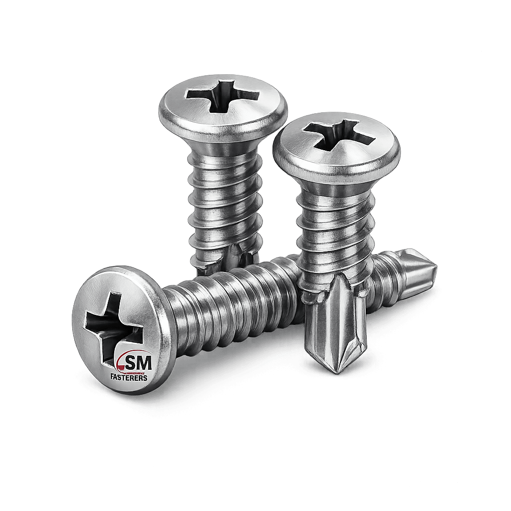
Unlike conventional bolted assemblies requiring:
- Pre-drilling
- Tapping
- Fastener installation
Self drilling screws eliminate secondary machining operations, significantly improving:
- Installation efficiency
- Alignment accuracy
- Structural reliability
- Labor productivity
- Repeatability under field conditions
Industrial Adoption Drivers
| Industry | Engineering Requirement | SDS Advantage |
|---|---|---|
| Structural Steel | Fast secondary framing | No pre-drilling |
| Oil & Gas Modules | Site assembly speed | Reduced installation stages |
| Power Plants | Sheet & equipment mounting | Controlled preload |
| Petrochemical | Corrosion resistance | Stainless & alloy grades |
| Offshore | Limited access installation | One-step fastening |
| Rail Infrastructure | Vibration-resistant joints | High clamp retention |
Within EPC environments, self drilling screws support modular construction philosophy, enabling rapid fabrication while maintaining structural integrity.
SM Fasteners manufactures SDS systems aligned with global project specifications requiring traceability, material certification, and dimensional compliance.
2. Technical Definition
A self drilling screw is a threaded fastener incorporating:
- Integrated drill point
- Thread forming or cutting section
- Load-bearing head
- Clamping shank
Functional Elements
| Component | Engineering Function |
|---|---|
| Drill Point | Penetrates substrate |
| Cutting Flutes | Remove chips |
| Lead Threads | Initiate tapping |
| Full Threads | Develop clamp force |
| Head | Transfers torque & load |
The drill point geometry is equivalent to a miniature twist drill designed for controlled penetration through metallic substrates.
3. Load Mechanics & Force Behaviour
Self drilling screws operate primarily as preloaded clamping fasteners.
Fundamental Load Principle
The joint integrity depends on clamping force, not screw shear capacity.
Where:
- = Preload (N)
- = Applied torque (Nm)
- = Nut factor (friction coefficient)
- = Nominal diameter (m)
Force Components in Installed Joint
| Load Type | Description |
|---|---|
| Tensile Load | Axial separation force |
| Shear Load | Lateral sliding |
| Clamp Force | Compression between members |
| Bearing Load | Surface contact pressure |
| Bending Load | Misalignment effects |
Torque–Tension Relationship
Only 10–15% of installation torque produces preload.
| Energy Distribution | Percentage |
|---|---|
| Thread Friction | 40–45% |
| Head Friction | 40–50% |
| Useful Clamp Load | 10–15% |
This explains why lubrication and coating selection critically influence joint performance.
4. Joint Design Principles
Self drilling screw joints must be engineered considering:
4.1 Thread Engagement Requirement
Minimum engagement:
4.2 Drill Capacity Matching
Incorrect drill point selection leads to:
- Work hardening
- Tip breakage
- Thread stripping
- Reduced preload
4.3 Joint Stack Design
Key parameters:
- Total material thickness
- Base material hardness
- Coating compatibility
- Thermal expansion mismatch
4.4 Clamp Force Behaviour
Preload must exceed operational loads:
Failure occurs when external forces unload the joint.
5. Failure Mechanisms
5.1 Fatigue Failure
Caused by fluctuating loads when preload insufficient.
Mitigation:
- Correct torque
- Hardened washers
- Controlled lubrication
5.2 Shear Failure
Occurs when joint slips.
Design Rule:
Shear loads must transfer via friction, not screw shank.
5.3 Hydrogen Embrittlement
Risk for hardened carbon steel SDS.
Controls at SM Fasteners:
- Baking after electroplating
- Hardness control
- ISO 4042 compliant finishing
5.4 Stress Corrosion Cracking
Common in:
- Chloride environments
- Offshore installations
- Chemical plants
Solution:
- Duplex stainless
- Nickel alloys
- PEEK fasteners where metallic corrosion risk exists
6. Functional Role in Industrial Assemblies
Self drilling screws are primarily used for:
- Thin steel-to-steel connections
- Sheet metal assemblies
- Equipment housings
- Roofing and cladding systems
- Cable tray installations
- HVAC structures
- Offshore module fabrication
They enable repeatable torque-controlled installation, making them suitable for automated or semi-automated assembly lines.
7. Preload Calculation — Worked Example
Given:
- Screw: M6 Self Drilling Screw
- Torque: 10 Nm
- Nut Factor: 0.20
Result: Approximate preload = 8.3 kN
This preload ensures resistance against vibration-induced loosening.
8. Engineering Advantages Over Conventional Fastening
| Parameter | Conventional Screw | Self Drilling Screw |
|---|---|---|
| Pre-drilling | Required | Not required |
| Installation Time | High | Low |
| Alignment Error | Possible | Minimal |
| Labor Dependency | High | Reduced |
| Field Productivity | Moderate | High |
9. Role Within SM Fasteners Manufacturing Philosophy
SM Fasteners integrates:
- Certified material sourcing
- Controlled thread forming
- ISO 9001 process validation
- Global dimensional compliance
- Engineering traceability
The objective is delivering procurement-ready fasteners suitable for EPC documentation review and third-party inspection.
10. Product Architecture of Self Drilling Screws


Self drilling screws are engineered systems where geometry directly determines drilling efficiency, torque transmission, load capacity, and service life.
Unlike conventional screws, every geometric parameter performs a defined mechanical function:
- Drill point → penetration capability
- Thread profile → load development
- Head geometry → torque transfer & sealing
- Drive interface → installation repeatability
SM Fasteners manufactures SDS configurations optimized for industrial assembly tolerances and global interchangeability requirements.
11. Classification of Self Drilling Screws
11.1 Based on Head Configuration
| Head Type | Engineering Purpose | Typical Application |
|---|---|---|
| Hex Washer Head | High torque transmission | Structural steel, roofing |
| Pan Head | Controlled clamp area | Electrical panels |
| Countersunk (CSK) | Flush surface | Architectural assemblies |
| Modified Truss Head | Large bearing surface | Thin sheet metal |
| Wafer Head | Low-profile fastening | HVAC systems |
| Flat Head | Embedded installations | Equipment housings |
Hex washer head designs dominate industrial applications due to superior torque capacity and washer sealing performance.
11.2 Based on Drive System
| Drive Type | Torque Capacity | Industrial Suitability |
|---|---|---|
| Hex External | Excellent | Structural & EPC |
| Phillips | Moderate | Light assemblies |
| Torx (Star) | Very High | Automated production |
| Square Drive | High | OEM fabrication |
| Combination Drive | Flexible | Maintenance work |
Engineering Trend:
EPC contractors increasingly specify Torx drives to reduce cam-out and torque variability.
11.3 Based on Drill Point (TEK Number)
The drill point determines maximum drilling thickness capability.
| TEK Point | Drill Capacity (Steel Thickness) | Application |
|---|---|---|
| TEK 1 | Up to 2 mm | Sheet metal |
| TEK 2 | 2–3 mm | Light steel |
| TEK 3 | 3–5 mm | Structural sheet |
| TEK 4 | 6–8 mm | Heavy steel |
| TEK 5 | 8–12 mm | Structural members |
Selection error between drill capacity and material thickness is the primary cause of installation failure.
11.4 Based on Thread Type
| Thread Form | Functional Behavior |
|---|---|
| Self-Tapping Thread | Forms mating thread |
| Fine Thread | Higher clamp load |
| Coarse Thread | Faster installation |
| Twin Lead Thread | Reduced installation time |
| Hi-Lo Thread | Soft material compatibility |
12. Dimensional Logic & Engineering Geometry

Self drilling screw performance depends on proportional relationships between:
- Diameter
- Thread pitch
- Drill flute length
- Head bearing surface
12.1 Standard Dimensional Specification Table
(Typical SM Fasteners Industrial Range)
| Size | Nominal Dia (mm) | Pitch (mm) | Head Dia (mm) | Drill Length (mm) | Length Range (mm) |
|---|---|---|---|---|---|
| #8 | 4.2 | 1.41 | 8.5 | 5 | 13–50 |
| #10 | 4.8 | 1.59 | 10.5 | 6 | 16–75 |
| #12 | 5.5 | 1.81 | 11.0 | 7 | 20–100 |
| #14 | 6.3 | 2.11 | 13.5 | 8 | 25–150 |
| M5 | 5.0 | 0.8 | 10 | 6 | 16–80 |
| M6 | 6.0 | 1.0 | 12 | 8 | 20–120 |
Dimensional tolerances maintained according to ISO and DIN thread standards.
12.2 Thread Engagement Principles
Minimum thread engagement:
| Base Material | Engagement Requirement |
|---|---|
| Structural Steel | ≥1× diameter |
| Aluminium | ≥1.5× diameter |
| Stainless Sheet | ≥1.2× diameter |
12.3 Drill Point Geometry Logic
Key design parameters:
- Point angle: 135°–145°
- Flute clearance angle
- Chip evacuation path
- Cutting edge hardness
Improper geometry results in excessive torque and thermal damage.
13. International Standards Compliance
Self drilling screws used in global EPC projects must conform to internationally accepted dimensional and mechanical standards.
SM Fasteners manufactures in accordance with multi-standard interchangeability requirements.
13.1 ISO Standards
| Standard | Description |
|---|---|
| ISO 1478 | Thread forming screw threads |
| ISO 15480 | Self drilling screw performance |
| ISO 898-1 | Mechanical properties |
| ISO 4042 | Electroplated coatings |
| ISO 3506 | Stainless steel fasteners |
| ISO 965 | Thread tolerances |
13.2 DIN Standards
| DIN Standard | Scope |
|---|---|
| DIN 7504 | Self drilling screws |
| DIN 7981 | Pan head screws |
| DIN 7982 | Countersunk screws |
| DIN 7500 | Thread forming screws |
DIN 7504 remains the most widely referenced SDS standard globally.
13.3 ASTM Standards
| ASTM | Description |
|---|---|
| ASTM C1513 | Self drilling tapping screws |
| ASTM F568M | Mechanical properties metric |
| ASTM A240 | Stainless steel material |
| ASTM B633 | Zinc coating |
| ASTM A193 | Alloy fasteners (high temp) |
13.4 British Standards (BS)
| BS Standard | Application |
|---|---|
| BS 4174 | Self tapping screws |
| BS EN ISO 1478 | Thread profile |
| BS EN 10204 | Inspection documentation |
14. Thread Standards & Tolerances
Thread System Compatibility Table
| Thread System | Standard | Typical Use |
|---|---|---|
| Metric | ISO 261 / ISO 965 | Global projects |
| UNC | ASME B1.1 | North America |
| UNF | ASME B1.1 | Aerospace & vibration |
| BSW | BS 84 | Legacy UK equipment |
| BSF | BS 84 | Fine pitch applications |
Tolerance classes typically supplied:
- 6g external thread (metric)
- 2A UNC
- 2A UNF
15. Mechanical Property Classes
Self drilling screws require hardened drill tips and controlled core ductility.
| Property Class | Ultimate Tensile Strength (MPa) | Yield Strength (MPa) | Application |
|---|---|---|---|
| Class 8.8 | 800 | 640 | General structural |
| Class 10.9 | 1040 | 940 | High strength |
| Class 12.9 | 1220 | 1100 | Heavy duty |
| A2-70 | 700 | 450 | Corrosion resistant |
| A4-80 | 800 | 600 | Offshore |
SM Fasteners maintains hardness gradients ensuring drill tip hardness exceeds thread body hardness.
16. Proof Load & Tensile Strength Table
| Size | Proof Load (kN) | Tensile Load (kN) |
|---|---|---|
| #8 | 6.0 | 8.0 |
| #10 | 8.5 | 11 |
| #12 | 11 | 15 |
| #14 | 14 | 19 |
| M5 | 9 | 12 |
| M6 | 13 | 18 |
Values depend on property class and material grade.
17. Dimensional Interchangeability Considerations
EPC procurement frequently demands cross-standard equivalence.
Engineering checks required:
- Head height compatibility
- Washer diameter equivalence
- Drive engagement depth
- Thread flank angle consistency
- Drill capacity equivalence
SM Fasteners supports multi-standard drawings and project-specific dimensional approvals.
18. Engineering Selection Criteria
Self drilling screw selection must consider:
Mechanical Factors
- Required clamp force
- Base metal thickness
- Joint fatigue exposure
Environmental Factors
- Corrosive media
- Temperature exposure
- Galvanic compatibility
Installation Factors
- Access limitations
- Tool torque capability
- Automation requirements
19. Procurement Specification Example
Typical EPC specification may include:
- DIN 7504 K
- Property Class 10.9
- Zinc Flake Coating
- ISO 965 Thread Tolerance
- EN 10204 3.1 Certification
- PMI Verification
- Traceability Marking
SM Fasteners engineering team supports full technical submittal packages aligned with project documentation procedures.
20. Materials Engineering for Self Drilling Screws
Material selection is the primary engineering determinant governing:
- Mechanical strength
- Drill performance
- Corrosion resistance
- Temperature capability
- Service life reliability
Self drilling screws require a dual-performance material behavior:
- High hardness at drill point
- Adequate ductility in threaded shank
SM Fasteners supplies a full industrial material range supporting global EPC specifications and severe-service applications.
21. Industrial Material Grades
21.1 Carbon Steel Grades
| Material | Standard | Typical Hardness | Application |
|---|---|---|---|
| C1022 | SAE / ASTM | 32–40 HRC | Standard SDS |
| C1018 | ASTM | Medium | Sheet metal |
| Boron Steel | DIN | High hardenability | Heavy drilling |
Advantages:
- High strength
- Economical production
- Excellent drill performance
Limitations:
- Requires protective coating
- Susceptible to corrosion
21.2 Alloy Steel Grades
| Grade | Standard | Service Condition |
|---|---|---|
| 4140 | ASTM A29 | Structural fastening |
| 4340 | ASTM | High fatigue loads |
| B7 Equivalent | ASTM A193 | Elevated temperature |
Used where:
- Higher preload required
- Cyclic loading present
- Structural safety critical
21.3 Stainless Steel Grades
| Grade | Standard | Corrosion Resistance | Application |
|---|---|---|---|
| A2-70 (304) | ISO 3506 | Atmospheric | Construction |
| A4-80 (316) | ISO 3506 | Marine | Offshore |
| 410 SS | ASTM | Hardenable | Drill point screws |
| 17-4 PH | ASTM A564 | High strength | Critical equipment |
Stainless SDS often use bi-metal construction:
- Hardened carbon steel drill tip
- Stainless body
21.4 Duplex & Super Duplex Stainless Steel
| Grade | PREN Value | Environment |
|---|---|---|
| Duplex 2205 | ~35 | Chloride exposure |
| Super Duplex 2507 | >40 | Offshore subsea |
Advantages:
- High strength
- Exceptional SCC resistance
- Long service life
21.5 Nickel & High-Performance Alloys
| Material | Max Temp | Industrial Use |
|---|---|---|
| Inconel 625 | 980°C | LNG & turbine |
| Inconel 718 | 700°C | Aerospace |
| Hastelloy C276 | Acid resistant | Chemical plants |
| Monel 400 | Seawater | Marine |
| Incoloy 825 | Sour service | Oil & Gas |
| SMO 254 | Chloride systems | Desalination |
SM Fasteners manufactures specialty alloy fasteners compliant with NACE MR0175 / ISO 15156 sour service requirements.
21.6 PEEK Fasteners (Advanced Engineering Polymer)
| Property | Value |
|---|---|
| Continuous Temp | 260°C |
| Corrosion Resistance | Excellent |
| Electrical Insulation | Outstanding |
| Chemical Resistance | Exceptional |
Applications:
- Semiconductor manufacturing
- Chemical reactors
- Electrical insulation zones
- Anti-galvanic assemblies
PEEK SDS solutions are engineered where metallic fasteners create contamination or galvanic corrosion risk.
22. Material Comparison Table
| Material | UTS (MPa) | Yield (MPa) | Corrosion Resistance | Relative Cost | Typical Industry |
|---|---|---|---|---|---|
| Carbon Steel | 800–1200 | High | Low | Low | Construction |
| Alloy Steel | 1000–1400 | Very High | Moderate | Medium | Structural |
| SS 304 | 700 | Medium | Good | Medium | Infrastructure |
| SS 316 | 800 | High | Excellent | Higher | Offshore |
| Duplex 2205 | 900 | Very High | Excellent | High | Oil & Gas |
| Inconel 625 | 850 | High | Exceptional | Premium | LNG |
| PEEK | 100 | Low | Absolute | Premium | Electronics |
23. Heat Treatment Processes
Key Objective:
Heat treatment creates the essential performance characteristic of self drilling screws.
Hard drill point + Tough load-bearing core
23.1 Process Sequence
- Austenitizing
- Oil or polymer quenching
- Tempering
- Surface stress relief
23.2 Typical Hardness Control
| Zone | Hardness Requirement |
|---|---|
| Drill Tip | 52–58 HRC |
| Thread Body | 32–40 HRC |
| Head | 28–36 HRC |
Hardness gradient prevents brittle fracture.
23.3 Hydrogen Embrittlement Prevention
SM Fasteners controls risk through:
- Post plating bake (200°C / 4 hrs)
- Hardness monitoring
- ISO 4042 process validation
Essential for high-strength SDS used in structural environments.
24. End-to-End Manufacturing Workflow


SM Fasteners operates an integrated manufacturing system aligned with ISO 9001 quality management.
24.1 Raw Material Verification
Incoming material inspection includes:
- Mill Test Certificate verification
- Chemical composition analysis
- PMI testing (Positive Material Identification)
- Mechanical property validation
Traceability maintained via heat number tracking.
24.2 Cold Heading / Forging
Cold heading advantages:
- Grain flow alignment
- Higher fatigue strength
- Material utilization efficiency
Forging forms:
- Head geometry
- Washer integration
- Drive recess
24.3 Drill Point Formation
Specialized tooling creates:
- Cutting lips
- Flute geometry
- Chip evacuation channels
Critical for drilling efficiency.
24.4 Thread Rolling vs Thread Cutting
| Method | Engineering Benefit |
|---|---|
| Thread Rolling | Increased fatigue life |
| Thread Cutting | Used for hard alloys |
Rolled threads produce compressive residual stresses improving durability.
24.5 Heat Treatment Integration
Continuous furnaces ensure:
- Uniform hardness
- Controlled microstructure
- Reduced distortion
24.6 Surface Preparation
Before coating:
- Alkaline cleaning
- Pickling
- Shot blasting
- Surface activation
24.7 Final Inspection & Sorting
Automated optical sorting verifies:
- Length
- Head height
- Thread pitch
- Drive integrity
- Tip geometry
25. Surface Engineering & Coatings


Surface finishing determines corrosion resistance and torque behavior.
25.1 Coating Types
| Coating | Thickness | Salt Spray Resistance | Application |
|---|---|---|---|
| Zinc Plating | 5–12 µm | 72–120 hrs | Indoor |
| HDG | 40–80 µm | 600+ hrs | Structural |
| Zinc Flake | 8–12 µm | 1000+ hrs | Automotive |
| Dacromet | Thin | High | Offshore |
| Mechanical Galvanized | Medium | Moderate | Construction |
| Passivated Stainless | — | Excellent | Marine |
25.2 Surface Finish Performance Comparison
| Finish | Corrosion Resistance | Friction Stability | Hydrogen Risk |
|---|---|---|---|
| Zinc Electroplate | Moderate | Stable | Medium |
| Zinc Flake | Excellent | Very Stable | Low |
| HDG | Excellent | Variable | Low |
| Phosphate | Low | Excellent | Very Low |
| PTFE Topcoat | High | Excellent | Very Low |
25.3 Corrosion Resistance vs Environment
| Environment | Recommended Material / Coating |
|---|---|
| Indoor Dry | Zinc Plated |
| Outdoor Urban | Zinc Flake |
| Marine Atmosphere | SS 316 / Duplex |
| Offshore Platform | Super Duplex |
| Chemical Plant | Hastelloy |
| H₂S Sour Service | Incoloy / NACE compliant |
| Electrical Isolation | PEEK |
26. Mechanical Properties — Grade Wise
| Property Class | Hardness | Tensile Strength (MPa) | Typical Use |
|---|---|---|---|
| 8.8 | 22–32 HRC | 800 | General |
| 10.9 | 32–39 HRC | 1040 | Structural |
| 12.9 | 39–44 HRC | 1220 | Heavy duty |
| A2-70 | HRB 95 | 700 | Corrosion resistant |
| A4-80 | HRB 100 | 800 | Marine |
27. Engineering Considerations for Severe Service
Critical selection parameters:
- Temperature cycling
- Chloride exposure
- Galvanic compatibility
- Installation torque control
- Inspection traceability
SM Fasteners engineering supports custom fastener design incorporating advanced alloys and polymer solutions tailored to project specifications.
28. Integration with SM Fasteners Quality System
Manufacturing controlled under:
- ISO 9001 certified QMS
- UKAF accredited inspection processes
- Batch traceability system
- Documented heat treatment validation
- Project-specific material control plans
Ensuring global procurement readiness for EPC, OEM, and infrastructure projects.
29. Inspection & Quality Control Framework
Self drilling screws used in EPC, oil & gas, infrastructure and heavy engineering projects are classified as critical joining components.
Therefore, inspection must verify:
- Dimensional compliance
- Mechanical performance
- Material integrity
- Surface treatment reliability
- Traceability documentation
SM Fasteners integrates inspection throughout the manufacturing lifecycle under an ISO 9001 certified Quality Management System with UKAF-accredited practices.
29.1 Incoming Material Inspection
| Inspection | Purpose |
|---|---|
| Mill Test Certificate Review | Verify heat chemistry |
| PMI Testing | Confirm alloy grade |
| Spectro Analysis | Elemental validation |
| Hardness Testing | Process suitability |
| Visual Examination | Surface defects |
Each production batch remains traceable to raw material heat number.
29.2 In-Process Inspection
Control stages include:
- Head formation verification
- Thread pitch measurement
- Drill tip geometry inspection
- Concentricity check
- Rolling integrity validation
Statistical Process Control (SPC) ensures dimensional stability.
29.3 Final Inspection & Testing
| Test | Standard Reference |
|---|---|
| Tensile Testing | ISO 898 / ASTM F606 |
| Proof Load Test | ISO 898 |
| Torque Test | DIN 7504 |
| Drill Performance Test | ISO 15480 |
| Coating Thickness | ISO 2178 |
| Salt Spray Test | ASTM B117 |
| Hardness Test | ISO 6508 |
| Thread Gauge Inspection | ISO 1502 |
29.4 Non-Destructive Examination (NDT)
Where project specifications require:
- Magnetic Particle Inspection (MPI)
- Dye Penetrant Testing (DPT)
- Ultrasonic Examination (UT)
- Eddy Current inspection (special alloys)
29.5 Documentation & Certification
SM Fasteners provides full project documentation packages:
| Document | Standard |
|---|---|
| EN 10204 3.1 MTC | Mandatory supply |
| EN 10204 3.2 Certification | Third-party validated |
| Heat Treatment Reports | Furnace traceability |
| Coating Compliance | ISO 4042 |
| Inspection Reports | Dimensional & mechanical |
| Certificate of Conformance | Project requirement |
30. Failure Analysis & Reliability Engineering
Typical failure modes evaluated during QA review:
| Failure Mode | Root Cause | Preventive Control |
|---|---|---|
| Drill Tip Breakage | Incorrect hardness | Heat treatment control |
| Thread Stripping | Over-torque | Torque specification |
| Fatigue Failure | Low preload | Joint design review |
| Hydrogen Embrittlement | Improper plating | Baking procedure |
| Galvanic Corrosion | Material mismatch | Alloy selection |
Engineering feedback loops allow corrective action within ISO 9001 systems.
31. Industry Applications
Self drilling screws serve across multiple high-reliability industrial sectors.
31.1 Construction & Structural Steel
Applications:
- Secondary framing
- Roofing systems
- Steel decking
- Facade systems
Engineering Requirement:
Fast installation with predictable clamp load.
31.2 Oil & Gas Industry
Upstream
- Rig structures
- Equipment enclosures
Midstream
- Pipeline accessories
- Compressor housings
Downstream
- Refinery panels
- Instrument mounting
Materials frequently specified:
- A4 stainless
- Duplex
- Incoloy
- NACE compliant alloys
31.3 Power Generation
- Turbine housing panels
- Cable tray systems
- Solar mounting
- Nuclear auxiliary systems
Thermal cycling resistance becomes primary selection criteria.
31.4 Petrochemical & Chemical Processing
Requirements:
- Acid resistance
- Chloride protection
- Stress corrosion resistance
Preferred materials:
Hastelloy, SMO 254, Duplex stainless.
31.5 LNG & Offshore Structures
Design considerations:
- Salt spray exposure
- Dynamic vibration
- Maintenance accessibility
Super Duplex and high-performance coatings commonly specified.
31.6 Automotive & Heavy Equipment
- Cab structures
- Equipment panels
- Agricultural machinery
Automation-compatible Torx drive systems are preferred.
31.7 Railways & Infrastructure
- Signaling equipment
- Bridge accessories
- Noise barriers
- Electrical enclosures
High fatigue resistance essential.
31.8 Shipbuilding & Marine
Challenges:
- Continuous seawater exposure
- Galvanic corrosion
- Cyclic loading
Typical materials:
A4-80, Duplex, Monel.
31.9 PEEK Fastener Applications
Used where metallic fasteners are unsuitable:
- Semiconductor plants
- Chemical reactors
- Electrical insulation zones
- MRI equipment
- Corrosion-sensitive assemblies
SM Fasteners manufactures engineered PEEK solutions supporting specialty industrial environments.
32. Export Capability & Global Supply Readiness
SM Fasteners supplies self drilling screws globally with export-ready logistics aligned to EPC procurement procedures.
32.1 Industrial Packaging
| Packaging Type | Purpose |
|---|---|
| VCI Packaging | Corrosion protection |
| Thread Caps | Mechanical protection |
| Heat-Sealed Bags | Moisture barrier |
| Batch Labeling | Traceability |
| Palletized Loads | Safe handling |
32.2 Export Crating
- ISPM-15 compliant fumigated wooden crates
- Containerized bulk shipment
- Custom project kitting
- Barcode traceability
32.3 Export Documentation
Typical supply documentation:
- Commercial Invoice
- Packing List
- Certificate of Origin
- EN 10204 3.1 / 3.2
- Inspection Release Note
- Test Certificates
- Heat Treatment Records
- Coating Compliance Reports
33. ENGINEERING TABLES
33.1 Mechanical Properties Table
| Property Class | Yield Strength MPa | Tensile Strength MPa | Hardness |
|---|---|---|---|
| 8.8 | 640 | 800 | 22–32 HRC |
| 10.9 | 940 | 1040 | 32–39 HRC |
| 12.9 | 1100 | 1220 | 39–44 HRC |
| A2-70 | 450 | 700 | HRB 95 |
| A4-80 | 600 | 800 | HRB 100 |
33.2 Tightening Torque Chart (Typical Values)
| Size | Grade 8.8 Dry (Nm) | Lubricated (Nm) |
|---|---|---|
| #8 | 4 | 3 |
| #10 | 6 | 4.5 |
| #12 | 9 | 7 |
| #14 | 14 | 10 |
| M5 | 7 | 5 |
| M6 | 12 | 9 |
33.3 Preload Calculation Formula
Example — M6 Screw
Torque = 12 Nm
Nut Factor = 0.2
Approximate clamp load = 10 kN
33.4 Thread Standards & Tolerances
| Thread | Standard | Tolerance |
|---|---|---|
| Metric | ISO 261 | 6g |
| UNC | ASME B1.1 | 2A |
| UNF | ASME B1.1 | 2A |
| BSW | BS 84 | Medium |
| BSF | BS 84 | Fine |
33.5 Surface Finish Performance Comparison
| Coating | Salt Spray (hrs) | Friction Stability | Use |
|---|---|---|---|
| Zinc Plated | 72–120 | Good | Indoor |
| Zinc Flake | 1000+ | Excellent | Automotive |
| HDG | 600+ | Moderate | Structural |
| PTFE | High | Excellent | Chemical |
| Stainless Passive | Excellent | Stable | Marine |
33.6 Corrosion Resistance vs Environment
| Environment | Recommended Material |
|---|---|
| Indoor | Zinc plated carbon steel |
| Outdoor | Zinc flake |
| Marine | SS 316 |
| Offshore | Super Duplex |
| Acidic | Hastelloy |
| H₂S | Incoloy / NACE |
| Electrical Isolation | PEEK |
33.7 Weight Chart — Self Drilling Screws
(Aligned with SM Fasteners Production Data — Approximate)
| Size | Length (mm) | Weight / Piece (g) | Weight / 100 pcs (kg) |
|---|---|---|---|
| #8 | 25 | 3.2 | 0.32 |
| #10 | 25 | 4.5 | 0.45 |
| #12 | 38 | 7.8 | 0.78 |
| #14 | 50 | 12.5 | 1.25 |
| M5 | 30 | 5.2 | 0.52 |
| M6 | 40 | 9.8 | 0.98 |
34. Procurement & Engineering Selection Checklist
Engineers should confirm:
- Required clamp load
- Base material thickness
- Drill capacity (TEK number)
- Corrosion environment
- Mechanical property class
- Coating requirement
- Inspection documentation level
- Traceability requirement
SM Fasteners provides technical support for complete engineering submittal approval.
ENGINEERING CONCLUSION
Self drilling screws represent a highly engineered fastening solution integrating:
- Drilling
- Thread formation
- Structural clamping
When designed, manufactured, and inspected under controlled systems such as those implemented by SM Fasteners, they deliver:
- Predictable mechanical performance
- Global standards compliance
- Reliable installation efficiency
- Long-term structural integrity
Through ISO 9001 certified manufacturing, UKAF-accredited inspection systems, advanced material capability—including Duplex, Nickel Alloys, and PEEK—and full export documentation readiness, SM Fasteners demonstrates capability aligned with global EPC, OEM, and industrial procurement requirements.