Anchor Bolt
1. Industry Context and Engineering Importance
Anchor bolts represent one of the most critical load-transfer components in civil, structural, mechanical, and heavy industrial installations. Unlike conventional threaded fasteners that join two manufactured components, anchor bolts form the primary interface between structural steel or equipment and concrete foundations.
They establish:
- Structural stability
- Equipment alignment integrity
- Seismic resistance
- Fatigue reliability
- Long-term foundation performance
Across EPC projects, anchor bolts are categorized as foundation-critical fasteners, meaning failure consequences extend beyond localized joint damage to system-level collapse risks.
Typical Engineering Responsibility Chain
| Discipline | Responsibility |
|---|---|
| Civil Engineer | Concrete design & embedment |
| Structural Engineer | Load transfer calculations |
| Mechanical Engineer | Equipment anchoring |
| Procurement | Standard & material compliance |
| QA/QC | Inspection & traceability verification |
Anchor bolts are therefore subject to multi-discipline engineering approval, unlike general bolting.
2. Industrial Sectors Using Anchor Bolts
Anchor bolts supplied by SM Fasteners support global infrastructure and heavy industry:
Construction & Structural Steel
- Steel column base plates
- Pre-engineered buildings
- Bridges and flyovers
- Metro infrastructure
Oil & Gas Facilities
- Compressor skids
- Pressure vessels
- Pipe racks
- Offshore topsides
- Flare stacks
Power Generation
- Turbine foundations
- Generator frames
- Boiler structures
- Wind turbine towers
Petrochemical & LNG Plants
- Reactor foundations
- Pump & motor bases
- Cryogenic installations
Heavy Equipment & OEM
- CNC machines
- Mining equipment
- Industrial presses
Marine & Shipbuilding
- Deck machinery
- Engine seating
- Dock infrastructure
Railway & Infrastructure
- Track structures
- Signal gantries
- Electrification supports
3. Technical Definition of Anchor Bolt
An Anchor Bolt is a threaded fastening element designed to:
Transmit tensile, shear, and overturning loads from structural or mechanical components into a concrete or masonry foundation through mechanical or bonded anchorage.
Unlike standard bolts, anchor bolts are partially embedded into concrete, creating a hybrid load system combining:
- Mechanical interlock
- Frictional resistance
- Bond strength
- Bearing resistance
Fundamental Components
| Component | Function |
|---|---|
| Embedded Portion | Load transfer into concrete |
| Threaded End | Nut engagement |
| Hook / Head / Plate | Pull-out resistance |
| Projection Length | Equipment mounting allowance |
| Grout Zone | Load distribution |
4. Functional Role in Structural Assemblies
Anchor bolts perform five simultaneous engineering functions:
- Resist uplift forces
- Transfer lateral shear
- Prevent overturning
- Maintain alignment
- Provide vibration resistance
Failure typically originates from improper preload, insufficient embedment, or incompatible material selection.
5. Load Mechanics and Force Behaviour
Anchor bolts operate under complex multi-axis loading.
Primary Load Types
| Load Type | Source | Effect |
|---|---|---|
| Tensile Load | Wind, uplift, seismic | Pull-out risk |
| Shear Load | Equipment motion | Sliding failure |
| Combined Load | Structural interaction | Stress concentration |
| Fatigue Load | Rotating equipment | Crack initiation |
| Dynamic Load | Impact or vibration | Loosening |
5.1 Tensile Load Transfer Mechanism
Tension loads are resisted by:
- Bond between steel and concrete
- Mechanical anchorage geometry
- Concrete cone resistance
Concrete failure often governs design rather than bolt strength.
Concrete Cone Failure Concept
When loaded in tension, concrete fractures in a conical shape originating from the embedment depth.
Key parameter:
Where:
- = concrete compressive strength
- = effective embedment depth
5.2 Shear Load Behaviour
Shear forces are transferred through:
- Bolt shank bearing
- Base plate friction
- Shear lugs or keys
Two failure modes exist:
- Steel shear failure
- Concrete edge breakout
Design codes (ACI 318 / EN 1992-4) normally require verification of both.
5.3 Combined Tension + Shear Interaction
Real industrial equipment rarely applies pure loading.
Interaction equation:
Where:
- N = Applied tension
- V = Applied shear
- Nu, Vu = capacities
6. Preload and Clamping Force Principles
Preload is essential even in embedded anchor systems.
Proper tightening ensures:
- Load sharing among bolts
- Vibration resistance
- Fatigue life extension
- Reduced joint slip
Bolt Preload Formula
Where:
| Parameter | Meaning |
|---|---|
| Fp | Preload |
| T | Applied torque |
| K | Nut factor |
| d | Nominal diameter |
Typical nut factor values:
| Condition | K Value |
|---|---|
| Dry | 0.20–0.25 |
| Zinc coated | 0.18 |
| Lubricated | 0.12–0.15 |
| PTFE coated | 0.10 |
Engineering Insight
Only 10–15% of tightening torque generates preload.
The remainder is lost to friction.
7. Joint Design Principles
Anchor bolt joint performance depends more on system design than bolt strength alone.
Key Design Parameters
| Parameter | Engineering Requirement |
|---|---|
| Embedment depth | Prevent pull-out |
| Edge distance | Avoid concrete cracking |
| Bolt spacing | Prevent cone overlap |
| Plate thickness | Prevent bending |
| Grout quality | Uniform load transfer |
| Sleeve allowance | Alignment adjustment |
Typical Base Plate Assembly
- Structural column
- Base plate
- Leveling nuts
- Grout layer
- Concrete foundation
- Anchor bolt embedment
8. Thread Engagement Requirements
Minimum thread engagement:
| Bolt Size | Minimum Engagement |
|---|---|
| M12–M20 | 1 × diameter |
| M24–M36 | 1.25 × diameter |
| M42+ | 1.5 × diameter |
Insufficient engagement leads to thread stripping before bolt yield.
9. Friction, Relaxation and Settlement
Anchor bolts experience preload loss due to:
- Concrete creep
- Grout settlement
- Thermal expansion mismatch
- Vibration
- Coating embedment
Expected preload loss:
10–25% within initial service period
Engineering mitigation:
- Retorque after commissioning
- Hardened washers
- Controlled lubrication
10. Failure Mechanisms in Anchor Bolts
10.1 Steel Tensile Failure
Occurs when bolt capacity < applied tension.
Prevented by correct property class selection.
10.2 Concrete Cone Failure
Most common failure mode.
Mitigation:
- Increase embedment
- Larger washer plate
- Higher concrete grade
10.3 Pull-Out Failure
Occurs in hooked or adhesive anchors when bond fails.
10.4 Shear Failure
Result of lateral equipment movement.
10.5 Fatigue Failure
Common in rotating equipment foundations.
Initiation sources:
- Thread root stress
- Misalignment
- Insufficient preload
10.6 Hydrogen Embrittlement
Risk in high-strength coated fasteners (>1000 MPa).
Mitigation applied by SM Fasteners:
- Controlled plating
- Post-bake de-embrittlement
- Hardness verification
10.7 Stress Corrosion Cracking (SCC)
Occurs in:
- Chloride environments
- H₂S service
- Marine exposure
Material selection must follow:
- NACE MR0175 / ISO 15156
11. Anchor Bolt vs Conventional Bolt — Engineering Comparison
| Parameter | Anchor Bolt | Conventional Bolt |
|---|---|---|
| Installation | Embedded in concrete | Through-hole assembly |
| Load Transfer | Concrete + steel | Steel-to-steel |
| Preload Criticality | Moderate–High | High |
| Design Codes | ACI / EN concrete codes | ISO bolting standards |
| Replacement | Difficult | Easy |
| Failure Impact | Structural | Localized |
12. Engineering Selection Philosophy
Selection of anchor bolts requires simultaneous evaluation of:
- Structural loads
- Environmental exposure
- Installation method
- Inspection accessibility
- Long-term maintenance requirements
SM Fasteners supports EPC clients with:
- Custom embedment geometries
- Heavy foundation anchoring systems
- High-alloy & corrosion-resistant materials
- PEEK fastener solutions for electrical isolation applications
13. Role of Certified Manufacturing
Anchor bolts must maintain full traceability due to structural criticality.
SM Fasteners manufacturing system integrates:
- ISO 9001 controlled procedures
- Heat traceability
- Raw material verification (MTC)
- Batch-controlled production
- Inspection documentation suitable for third-party audits
14. Anchor Bolt Classification Philosophy
Anchor bolts are engineered according to load transfer method, installation condition, and foundation interaction rather than head configuration alone.
Engineering classification used in global EPC projects:
| Classification Basis | Categories |
|---|---|
| Installation Stage | Cast-in / Post-Installed |
| Anchorage Mechanism | Mechanical / Bonded |
| Geometry | Hooked / Headed / Plate / Straight |
| Load Type | Tension / Shear / Dynamic |
| Service Environment | Structural / Offshore / Chemical |
SM Fasteners manufactures anchor bolts aligned with international project specifications and customized embedment designs.
15. Major Anchor Bolt Types
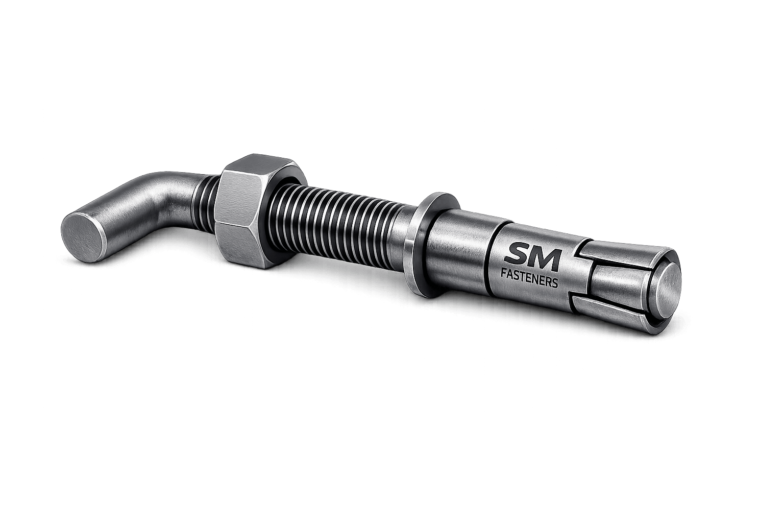
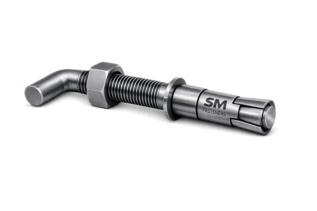
15.1 L-Type Anchor Bolt
Geometry: 90° bent end.
Load Resistance:
- Mechanical anchorage via hook
- Suitable for moderate tensile loads
Applications
- Structural columns
- Light machinery
- Building steelwork
| Parameter | Engineering Characteristic |
|---|---|
| Manufacturing | Hot bending or forging |
| Installation | Cast-in-place |
| Advantages | Simple, economical |
| Limitation | Lower pull-out resistance |
15.2 J-Type Anchor Bolt
Geometry: J-shaped hook.
Provides improved resistance compared to L-type due to longer bearing path.
Used extensively in:
- Steel structures
- Pipe supports
- Secondary foundations
15.3 Straight Anchor Bolt with Nut & Washer
Straight threaded rod anchored by:
- Double nuts
- Anchor plates
- Chemical bonding
Engineering Advantage
- Adjustable positioning
- High precision alignment
Preferred in EPC and turbine installations.
15.4 Headed anchor bolt
Forged hex or square head at embedded end.
Provides superior mechanical anchorage.
| Feature | Benefit |
|---|---|
| Forged head | High tensile capacity |
| No bending stress | Improved fatigue life |
| Uniform load distribution | Reduced concrete cracking |
Common in:
- Power plants
- Offshore modules
- Heavy equipment bases
15.5 Plate Anchor Bolt
Includes welded or forged anchor plate.
Used where extreme uplift loads exist.
Typical sectors:
- Wind towers
- Petrochemical reactors
- Large compressors
15.6 Sleeve Anchor Systems
Include sleeve allowing adjustment.
Engineering Purpose:
- Alignment tolerance
- Thermal expansion allowance
15.7 Post-Installed Mechanical Anchors
Installed after concrete curing.
Types include:
- Wedge anchors
- Expansion anchors
- Undercut anchors
Load transfer through expansion pressure.
15.8 Chemical / Adhesive Anchor Bolts
Bonded using epoxy or polyester resin.
Advantages:
- High tensile capacity
- Suitable for retrofit applications
- Minimal edge stress
15.9 Double-End Stud Anchor Bolt
Threaded both ends.
Used in:
- Rotating machinery
- Pump installations
- Skid assemblies
15.10 Insulated Anchor Bolts (PEEK Integration)
SM Fasteners supplies PEEK-based anchoring systems where:
- Electrical isolation required
- Cryogenic service exists
- Corrosion risk is severe
Applications:
- LNG terminals
- Offshore electrical modules
- Hydrogen facilities
16. Dimensional Logic & Geometry Engineering
Anchor bolt geometry directly influences performance.
Critical Dimensional Parameters
| Parameter | Symbol | Engineering Function |
|---|---|---|
| Nominal Diameter | d | Load capacity |
| Thread Pitch | P | Load distribution |
| Embedment Depth | hef | Pull-out resistance |
| Projection Length | Lp | Installation clearance |
| Bend Radius | R | Stress reduction |
| Edge Distance | C | Concrete integrity |
Embedment Depth Guideline
| Bolt Diameter | Typical Embedment |
|---|---|
| M12 | 120–150 mm |
| M16 | 160–220 mm |
| M20 | 200–300 mm |
| M24 | 250–400 mm |
| M30 | 350–500 mm |
| M36 | 450–700 mm |
| M42 | 600–900 mm |
Actual design governed by ACI 318 or EN 1992-4 calculations.
17. Standard Dimensional Specification Table
Metric Anchor Bolt Dimensions (Typical Reference)
| Size | Pitch (mm) | Across Flats (mm) | Nut Height (mm) | Washer OD (mm) | Recommended Hole |
|---|---|---|---|---|---|
| M12 | 1.75 | 19 | 10 | 24 | 14 |
| M16 | 2.0 | 24 | 13 | 30 | 18 |
| M20 | 2.5 | 30 | 16 | 37 | 22 |
| M24 | 3.0 | 36 | 19 | 44 | 26 |
| M30 | 3.5 | 46 | 24 | 56 | 33 |
| M36 | 4.0 | 55 | 29 | 66 | 39 |
| M42 | 4.5 | 65 | 34 | 78 | 45 |
| M48 | 5.0 | 75 | 38 | 92 | 52 |
Dimensions aligned with ISO nut & washer standards.
18. Thread Standards & Tolerances
Anchor bolts must comply with global thread systems.
Thread System Comparison
| Standard | Region | Angle | Typical Use |
|---|---|---|---|
| ISO Metric | Global | 60° | EPC projects |
| UNC | USA | 60° | Structural steel |
| UNF | USA | 60° | High preload |
| BSW | UK | 55° | Legacy systems |
| BSF | UK | 55° | Precision assemblies |
Metric Thread Tolerances
| Class | Application |
|---|---|
| 6g | Standard bolt tolerance |
| 6H | Nut tolerance |
| 4h | Precision fit |
SM Fasteners maintains CNC-controlled threading compliant with ISO 965 tolerances.
19. Applicable International Standards
Anchor bolts fall under multiple governing standards.
ISO Standards
| Standard | Scope |
|---|---|
| ISO 898-1 | Mechanical properties |
| ISO 4014 / 4017 | Hex bolts reference |
| ISO 965 | Thread tolerances |
| ISO 3506 | Stainless fasteners |
| ISO 10684 | Hot-dip galvanizing |
ASTM Standards (Widely Used in Oil & Gas)
| Standard | Application |
|---|---|
| ASTM F1554 | Structural anchor bolts |
| ASTM A307 | General purpose |
| ASTM A193 | High temperature |
| ASTM A320 | Low temperature |
| ASTM A194 | Heavy hex nuts |
| ASTM F436 | Hardened washers |
DIN Standards
| Standard | Description |
|---|---|
| DIN 529 | Foundation bolts |
| DIN 976 | Threaded rods |
| DIN 931/933 | Dimensional references |
British Standards
| Standard | Scope |
|---|---|
| BS 4190 | ISO metric bolts |
| BS EN 14399 | Structural bolting |
| BS 3643 | Thread forms |
Concrete Design Codes Referenced
| Code | Region |
|---|---|
| ACI 318 | USA |
| EN 1992-4 | Europe |
| IS 456 | India |
| IS 800 | Structural steel |
20. Mechanical Property Classes (Overview)
Anchor bolt strength defined by property class or ASTM grade.
| Property Class | Yield (MPa) | UTS (MPa) | Typical Use |
|---|---|---|---|
| 4.6 | 240 | 400 | Light structures |
| 5.8 | 400 | 500 | General foundation |
| 8.8 | 640 | 800 | Industrial equipment |
| 10.9 | 900 | 1000 | Heavy machinery |
| 12.9 | 1080 | 1200 | Special applications |
Selection must consider hydrogen embrittlement risk.
21. Interchangeability Considerations
Critical for global procurement.
| Parameter | Risk |
|---|---|
| Thread mismatch | Assembly failure |
| Property class mismatch | Structural failure |
| Coating thickness | Fit interference |
| Nut compatibility | Loss of preload |
SM Fasteners provides cross-standard manufacturing ensuring ISO–ASTM interchangeability where permitted by specification.
22. Dimensional Engineering Considerations for EPC Projects
Anchor bolt geometry must account for:
- Template installation accuracy
- Tolerance stack-up
- Grout thickness variation
- Thermal expansion
- Future equipment replacement
Typical EPC tolerance:
| Parameter | Typical Tolerance |
|---|---|
| Bolt projection | ±3 mm |
| Bolt spacing | ±2 mm |
| Verticality | 1:100 |
23. Anchor Bolt Weight Chart (SM Fasteners Reference)
Approximate theoretical weights (carbon steel).
| Size | Weight / Piece (kg) | Weight / 100 pcs (kg) |
|---|---|---|
| M12 × 300 | 0.27 | 27 |
| M16 × 400 | 0.63 | 63 |
| M20 × 500 | 1.23 | 123 |
| M24 × 600 | 2.12 | 212 |
| M30 × 750 | 4.18 | 418 |
| M36 × 900 | 7.50 | 750 |
| M42 × 1000 | 11.5 | 1150 |
| M48 × 1200 | 18.2 | 1820 |
Weight charts used for:
- Logistics planning
- Structural dead-load calculations
- Export packaging design
24. Engineering Selection Summary
Proper anchor bolt selection requires simultaneous verification of:
- Geometry suitability
- Applicable international standards
- Thread compatibility
- Mechanical class
- Installation methodology
SM Fasteners supports EPC and OEM buyers through:
- Custom drawing-based manufacturing
- Heavy-diameter anchor systems
- Precision thread rolling capability
- Certified dimensional control under ISO 9001 quality systems
25. Material Engineering Philosophy for Anchor Bolts
Material selection is the single most critical engineering decision governing anchor bolt reliability, service life, and structural safety.
Unlike conventional bolting, anchor bolts often operate under:
- Long-term static tension
- Cyclic vibration loads
- Embedded concrete alkalinity
- Moisture ingress
- Chemical exposure
- Temperature gradients
- Limited inspection accessibility
Therefore, materials must be selected based on mechanical performance + environmental compatibility + code compliance.
SM Fasteners manufactures anchor bolts across a full industrial material spectrum, enabling EPC procurement alignment worldwide.
26. Industrial Material Grades Used for Anchor Bolts
26.1 Carbon Steel Anchor Bolts
Most widely used material category.
Typical Grades:
- ASTM F1554 Grade 36 / 55 / 105
- ASTM A307
- IS 2062
- EN S355
Advantages
- High structural strength
- Economic production
- Excellent machinability
Limitations
- Requires corrosion protection
Applications:
- Buildings
- Infrastructure
- General equipment foundations
26.2 Alloy Steel Anchor Bolts
Used where higher strength or temperature resistance is required.
Common Grades:
- ASTM A193 B7
- ASTM A193 B16
- EN 1.7225 (42CrMo4)
Applications:
- Petrochemical plants
- Pressure vessels
- High-load equipment
- Power generation turbines
26.3 Stainless Steel Anchor Bolts
Selected primarily for corrosion resistance.
Typical Grades:
| Grade | UNS | Key Property |
|---|---|---|
| SS304 | S30400 | General corrosion resistance |
| SS316 | S31600 | Chloride resistance |
| SS316L | S31603 | Weldability |
| SS321 | S32100 | Elevated temperature |
| SS904L | N08904 | Acid resistance |
26.4 Duplex & Super Duplex Stainless Steels
High-strength corrosion-resistant materials.
| Grade | Yield Strength | Key Benefit |
|---|---|---|
| Duplex 2205 | ~450 MPa | Chloride SCC resistance |
| Super Duplex 2507 | ~550 MPa | Offshore durability |
Applications:
- Offshore platforms
- Desalination plants
- Marine structures
26.5 Nickel Alloy Anchor Bolts
Used in extreme environments.
| Material | Service Condition |
|---|---|
| Inconel 625 | High temperature & corrosion |
| Incoloy 825 | Acid environments |
| Monel 400 | Seawater service |
| Hastelloy C276 | Chemical processing |
| Nickel 200 | Caustic applications |
26.6 SMO 254 Anchor Bolts
Super austenitic stainless steel.
Suitable for:
- Seawater immersion
- Chloride-rich environments
- Offshore LNG facilities
26.7 PEEK Anchor Fasteners (Advanced Applications)
SM Fasteners supplies PEEK (Polyether Ether Ketone) fastener solutions where metallic anchoring is unsuitable.
Engineering Advantages:
- Electrical insulation
- Zero galvanic corrosion
- Cryogenic compatibility
- Chemical inertness
- Lightweight
Applications:
- Hydrogen plants
- Semiconductor facilities
- LNG instrumentation
- Electrical isolation mounts
27. Material Comparison Table
| Material | UTS (MPa) | Yield (MPa) | Corrosion Resistance | Temperature Limit | Cost Level | Typical Industry |
|---|---|---|---|---|---|---|
| Carbon Steel | 400–800 | 240–640 | Low | 300°C | Low | Construction |
| Alloy Steel B7 | 860 | 720 | Moderate | 450°C | Medium | Oil & Gas |
| SS304 | 515 | 205 | Good | 425°C | Medium | Infrastructure |
| SS316 | 515 | 205 | Very Good | 450°C | Medium | Marine |
| Duplex 2205 | 800 | 450 | Excellent | 300°C | High | Offshore |
| Super Duplex | 950 | 550 | Superior | 300°C | High | Offshore/LNG |
| Inconel 625 | 930 | 480 | Exceptional | 1000°C | Very High | Aerospace/LNG |
| SMO 254 | 650 | 300 | Extreme | 350°C | High | Seawater |
| PEEK | 95 | 90 | Absolute | 260°C | Specialized | Electrical |
28. Corrosion Resistance vs Environment
| Environment | Recommended Material |
|---|---|
| Indoor Dry | Carbon Steel |
| Outdoor Atmosphere | HDG Carbon Steel |
| Coastal | SS316 / Duplex |
| Seawater Immersion | Super Duplex / SMO 254 |
| Acid Processing | Hastelloy |
| H₂S Sour Service | Controlled hardness B7 / Duplex |
| LNG Cryogenic | A320 L7 / Stainless |
| Electrical Isolation | PEEK |
29. Mechanical Properties by Property Class
| Property Class | Yield Strength (MPa) | Tensile Strength (MPa) | Hardness Range |
|---|---|---|---|
| 4.6 | 240 | 400 | 120–160 HB |
| 5.8 | 400 | 500 | 150–190 HB |
| 8.8 | 640 | 800 | 22–34 HRC |
| 10.9 | 900 | 1000 | 32–39 HRC |
| 12.9 | 1080 | 1200 | 39–44 HRC |
NACE MR0175 Limitation:
Hardness typically ≤ 22 HRC for sour service.
30. Heat Treatment Processes
Heat treatment defines final mechanical performance.
30.1 Normalizing
- Grain refinement
- Improved toughness
- Used for structural grades
30.2 Quenching & Tempering (Q&T)
Process:
- Austenitizing
- Rapid quenching
- Controlled tempering
Produces:
- High strength
- Improved fatigue resistance
Applied to:
- Grade 8.8
- B7
- 10.9 anchor bolts
30.3 Solution Annealing (Stainless Steels)
Removes carbide precipitation.
Benefits:
- Restores corrosion resistance
- Prevents intergranular attack
30.4 Stress Relieving
Essential for:
- Bent anchor bolts
- Welded plate anchors
Prevents residual stress cracking.
30.5 Hydrogen De-Embrittlement Baking
Mandatory after electroplating for high-strength fasteners.
Typical parameters:
- 200°C
- 4–24 hours
Implemented under SM Fasteners controlled procedures.
31. End-to-End Manufacturing Workflow
SM Fasteners integrates full manufacturing traceability aligned with ISO 9001 systems.
Step 1 — Raw Material Verification
Incoming inspection includes:
- Mill Test Certificate (EN 10204 3.1)
- Chemical analysis verification
- Ultrasonic bar inspection
- Heat number traceability
Step 2 — Material Cutting
- CNC band sawing
- Length tolerance control
- Heat identification retention
Step 3 — Forging / Forming
Methods:
| Method | Application |
|---|---|
| Hot forging | Headed anchors |
| Cold forming | Smaller diameters |
| Hot bending | L & J anchors |
| Plate welding | Heavy anchors |
Forging improves grain flow and fatigue resistance.
Step 4 — Machining Operations
Performed using CNC equipment:
- Thread preparation
- End facing
- Chamfering
- Tolerance finishing
Step 5 — Thread Manufacturing
Thread Rolling (Preferred)
- Compressive grain structure
- Increased fatigue strength
Thread Cutting
- Used for large diameters or special alloys
Step 6 — Heat Treatment
Performed under calibrated furnaces with:
- Temperature recording
- Batch traceability
- Hardness verification
Step 7 — Surface Preparation
- Shot blasting
- Pickling
- Passivation (stainless)
Step 8 — Coating Application
(covered below)
Step 9 — Final Inspection
- Dimensional verification
- Mechanical testing
- Marking confirmation
Step 10 — Identification & Traceability
Each batch marked with:
- Heat number
- Grade
- Manufacturer identification (SM Fasteners)
32. Surface Engineering & Corrosion Protection
Anchor bolts require engineered surface systems.
Surface Finish Comparison Table
| Coating | Thickness | Corrosion Resistance | Temperature Limit | Typical Use |
|---|---|---|---|---|
| Black Oxide | Minimal | Low | 300°C | Indoor |
| Zinc Electroplating | 5–12 µm | Moderate | 120°C | Machinery |
| Hot Dip Galvanizing | 70–100 µm | High | 200°C | Structural |
| Mechanical Galvanizing | Uniform | High | 200°C | Structural |
| PTFE / Xylan | Low friction | High | 260°C | Chemical |
| Dacromet / Geomet | Excellent | 300°C | Automotive | |
| Epoxy Coating | Barrier protection | Excellent | 120°C | Marine |
| Passivation | Chemical resistance | High | 400°C | Stainless |
| Nickel Plating | Decorative + protection | Moderate | 400°C | Special |
33. Coating Selection Engineering Logic
Selection depends on:
- Environment
- Preload requirement
- Friction coefficient
- Hydrogen embrittlement risk
- Inspection requirements
Example:
| Environment | Recommended Coating |
|---|---|
| Structural outdoor | Hot Dip Galvanized |
| Offshore | Duplex Stainless |
| Chemical | PTFE coated |
| High preload | Mechanical galvanizing |
| Sour service | Controlled coating + hardness |
34. Friction Coefficient vs Coating
| Coating | Friction Coefficient |
|---|---|
| Dry Steel | 0.20–0.25 |
| Zinc Plated | 0.18 |
| HDG | 0.22 |
| PTFE | 0.10 |
| Xylan | 0.08–0.12 |
Critical for torque calculation accuracy.
35. Manufacturing Quality Integration at SM Fasteners
SM Fasteners manufacturing systems ensure:
- ISO 9001 process control
- UKAF-recognized quality compliance
- Batch traceability
- EPC project documentation readiness
- Capability for large-diameter custom anchor bolts
- Exotic alloy manufacturing
- PEEK engineered solutions
36. Inspection & Quality Control Philosophy
Anchor bolts are classified as structural safety components.
Failure may result in:
- Structural instability
- Equipment misalignment
- Fatigue cracking
- Catastrophic operational shutdown
Therefore, inspection extends beyond dimensional verification into material integrity, mechanical performance, and traceability validation.
SM Fasteners integrates inspection into every production stage under ISO 9001 quality management systems.
37. Incoming Material Inspection
Before manufacturing begins, raw material verification includes:
| Inspection | Method | Purpose |
|---|---|---|
| Chemical Composition | Spectrometer | Alloy confirmation |
| MTC Review | EN 10204 3.1 | Heat traceability |
| Ultrasonic Testing | UT | Internal defect detection |
| Visual Inspection | ASTM A484 | Surface integrity |
| Diameter Verification | Vernier/Micrometer | Dimensional conformity |
Heat numbers remain traceable throughout production.
38. In-Process Manufacturing Inspection
Performed at controlled checkpoints.
| Stage | Inspection Activity |
|---|---|
| Forging | Grain flow verification |
| Bending | Radius conformity |
| Thread Rolling | Pitch & flank angle check |
| Heat Treatment | Furnace calibration review |
| Coating | Thickness measurement |
Statistical process control ensures repeatability.
39. Dimensional Inspection Requirements
Critical parameters:
- Overall length
- Projection length
- Thread length
- Straightness
- Perpendicularity
- Bend angle
- Plate alignment (plate anchors)
Typical tolerances:
| Parameter | Tolerance |
|---|---|
| Length | ±2 mm |
| Thread Pitch | ISO 965 |
| Straightness | ≤ 1/1000 length |
| Bend Angle | ±2° |
40. Mechanical Testing
Conducted per ISO 898-1 and ASTM standards.
Mandatory Tests
| Test | Standard | Purpose |
|---|---|---|
| Tensile Test | ISO 6892 | Strength verification |
| Proof Load Test | ISO 898 | Elastic limit validation |
| Hardness Test | Rockwell/Brinell | Heat treatment control |
| Impact Test | ASTM A370 | Low-temperature service |
| Bend Test | Project specific | Ductility |
41. Non-Destructive Testing (NDT)
Required for critical projects.
| Method | Detection Capability |
|---|---|
| Magnetic Particle (MPI) | Surface cracks |
| Ultrasonic Testing | Internal flaws |
| Dye Penetrant (DPT) | Micro-cracks |
| Radiography | Weld inspection |
| Eddy Current | Surface discontinuities |
42. Positive Material Identification (PMI)
PMI testing ensures alloy integrity.
Used extensively in:
- Offshore projects
- Refineries
- LNG plants
- Nuclear facilities
SM Fasteners performs handheld XRF PMI verification upon request.
43. Documentation & Certification
Typical EPC documentation package:
| Document | Standard |
|---|---|
| Mill Test Certificate | EN 10204 3.1 / 3.2 |
| Heat Treatment Report | ISO compliant |
| Mechanical Test Report | ASTM / ISO |
| Dimensional Inspection Report | Project format |
| Coating Certificate | ISO 10684 |
| Certificate of Conformity | Manufacturer declaration |
All documentation traceable to manufacturing batch.
44. Failure Prevention Through Quality Control
Major failure causes addressed:
| Failure Mode | Prevention Method |
|---|---|
| Concrete breakout | Embedment verification |
| Thread stripping | Gauge inspection |
| Hydrogen embrittlement | Post-bake process |
| Fatigue cracking | Rolled threads |
| SCC | Correct alloy selection |
45. Industrial Application Engineering
45.1 Construction & Structural Steel
Anchor bolts secure:
- Steel columns
- Bridge bearings
- Transmission towers
- Metro structures
Primary load: static tension + seismic forces
45.2 Oil & Gas Industry
Applications:
- Compressor foundations
- Pipe racks
- Storage tanks
- Offshore modules
Requirements:
- NACE MR0175 compliance
- Corrosion-resistant alloys
- High preload reliability
45.3 Power Generation
Used in:
- Gas turbines
- Steam turbines
- Wind turbine towers
- Boiler structures
Critical requirement: vibration fatigue resistance.
45.4 Petrochemical & Chemical Plants
Exposure to:
- Acids
- Chlorides
- Solvents
Typical materials:
- SS316
- Duplex
- Hastelloy
- PTFE-coated anchors
45.5 LNG & Cryogenic Installations
Materials:
- ASTM A320 L7
- Stainless steel
- Nickel alloys
Must maintain toughness below −160°C.
45.6 Automotive & Heavy Equipment
Applications:
- Robotic assembly lines
- Press foundations
- CNC machinery anchoring
Requires alignment precision.
45.7 Railways & Infrastructure
- Electrification poles
- Signaling gantries
- Track structures
Designed for cyclic dynamic loading.
45.8 Shipbuilding & Marine Engineering
Exposure:
- Salt spray
- Immersion
- Wave loading
Preferred materials:
- Duplex
- Super Duplex
- SMO 254
45.9 PEEK Anchor Applications
Used where metal anchors are unsuitable:
- Electrical isolation mounts
- Hydrogen production systems
- Semiconductor plants
- High-purity chemical systems
46. Export Packaging & Logistics Engineering
SM Fasteners supplies globally with engineered packaging systems.
Industrial Packaging
| Method | Purpose |
|---|---|
| VCI Wrapping | Corrosion prevention |
| Thread Protectors | Damage prevention |
| Oil Coating | Transit protection |
| Heat Number Tagging | Traceability |
Export Crating
- ISPM-15 fumigated wooden crates
- Steel pallets for heavy anchors
- Moisture barrier packing
- Container load optimization
47. Global Supply & Procurement Capability
SM Fasteners supports EPC buyers through:
- Custom drawing manufacturing
- Large-diameter anchor production
- Exotic alloy capability
- Small batch + bulk production
- International logistics coordination
- Project-based documentation control
Certifications integrated:
- ISO 9001 Quality Management
- MSME recognized manufacturing
- UKAF accredited systems
48. COMPLETE ENGINEERING TABLES
48.1 Proof Load & Tensile Strength Table
| Size | Grade 4.6 Proof Load (kN) | Grade 8.8 Proof Load (kN) | Grade 10.9 Proof Load (kN) |
|---|---|---|---|
| M12 | 22 | 45 | 64 |
| M16 | 39 | 82 | 116 |
| M20 | 61 | 128 | 181 |
| M24 | 88 | 186 | 262 |
| M30 | 142 | 300 | 424 |
| M36 | 207 | 437 | 618 |
| M42 | 287 | 606 | 857 |
48.2 Tightening Torque Chart
(Approximate values)
| Size | Grade | Dry Torque (Nm) | Lubricated Torque (Nm) |
|---|---|---|---|
| M12 | 8.8 | 85 | 65 |
| M16 | 8.8 | 210 | 160 |
| M20 | 8.8 | 410 | 310 |
| M24 | 8.8 | 710 | 530 |
| M30 | 8.8 | 1400 | 1050 |
| M36 | 8.8 | 2450 | 1850 |
48.3 Preload Calculation — Worked Engineering Example
Given
- Bolt: M24 Grade 8.8
- Torque Applied: 700 Nm
- Nut Factor (lubricated): 0.14
- Diameter: 24 mm
Result:
Approximate preload = 208 kN
48.4 Thread Standards & Tolerance Table
| Thread | Pitch Example | Tolerance | Usage |
|---|---|---|---|
| Metric M24 | 3.0 mm | 6g/6H | Global EPC |
| UNC 1″ | 8 TPI | 2A/2B | USA structures |
| UNF 1″ | 12 TPI | 2A/2B | High preload |
| BSW | 8 TPI | Medium fit | Legacy UK |
| BSF | Fine | Precision | Maintenance |
48.5 Surface Finish Performance Comparison
| Coating | Corrosion Resistance | Friction Stability | Maintenance Need |
|---|---|---|---|
| Black | Low | Stable | High |
| Zinc | Medium | Moderate | Medium |
| HDG | High | Variable | Low |
| PTFE | Very High | Excellent | Low |
| Duplex Stainless | Extreme | Excellent | Minimal |
48.6 Anchor Bolt Weight Reference Chart
(Aligned with SM Fasteners production data)
| Size & Length | Weight/Pc (kg) | Weight/100 pcs (kg) |
|---|---|---|
| M16 × 400 | 0.63 | 63 |
| M20 × 500 | 1.23 | 123 |
| M24 × 600 | 2.12 | 212 |
| M30 × 750 | 4.18 | 418 |
| M36 × 900 | 7.50 | 750 |
| M42 × 1000 | 11.5 | 1150 |
| M48 × 1200 | 18.2 | 1820 |
49. Engineering Selection Checklist
Before procurement approval:
✔ Verify applicable design code
✔ Confirm material compatibility
✔ Check embedment design
✔ Validate mechanical properties
✔ Confirm coating system
✔ Review certification package
✔ Confirm installation torque specification
50. SM FASTENERS — ENGINEERED MANUFACTURING ADVANTAGE
SM Fasteners demonstrates full industrial capability through:
- ISO 9001 certified manufacturing systems
- UKAF-accredited quality compliance
- MSME recognized production infrastructure
- Advanced alloy manufacturing expertise
- PEEK fastener engineering capability
- Complete inspection & traceability control
- EPC-ready documentation and export logistics
The integrated engineering, manufacturing, inspection, and documentation framework ensures anchor bolts supplied by SM Fasteners meet the stringent reliability expectations of global infrastructure, energy, and heavy industry projects.