

STEP BOLT
1. Industry Context
Step bolts are specialized structural and mechanical fasteners designed to perform dual functional roles:
- Primary Mechanical Fastening
- Integrated Load-Bearing Step or Support Surface
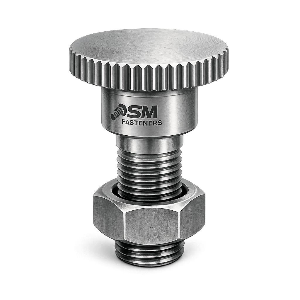
Unlike conventional bolts intended solely for clamping, step bolts form functional structural interfaces, commonly acting as:
- Ladder climbing steps
- Tower access footholds
- Transmission structure steps
- Equipment access supports
- Structural positioning stops
- Alignment or load transfer studs
They are widely deployed in industries where human access, repeat load cycling, and environmental exposure coexist.
Primary Industrial Sectors
| Industry | Functional Purpose |
|---|---|
| Transmission & Telecom Towers | Climbing footholds |
| Power Generation | Boiler access & maintenance steps |
| Oil & Gas | Platform access systems |
| Infrastructure | Bridge inspection access |
| Railways | Signal and gantry structures |
| Petrochemical | Reactor platform climbing systems |
| Shipbuilding | Vertical access structures |
| Heavy Equipment | Maintenance access points |
Step bolts must simultaneously satisfy:
- Structural fastening requirements
- Human safety load requirements
- Corrosion resistance expectations
- Fatigue durability criteria
This dual requirement differentiates them from standard hex bolts or carriage bolts.
SM Fasteners manufactures step bolts under controlled ISO 9001 quality systems, ensuring compliance with global EPC procurement expectations.
2. Technical Definition
Engineering Definition
A Step Bolt is a headed threaded fastener incorporating an extended cylindrical or formed shoulder designed to function as a load-bearing step or spacer while maintaining threaded clamping capability.
Basic Geometry Elements
- Head section
- Load-bearing step/shoulder
- Transition fillet radius
- Threaded shank
- Nut engagement zone
The shoulder diameter is intentionally larger than the thread diameter.
This provides:
- Increased bending resistance
- Reduced contact stress
- Stable foot engagement
- Controlled load transfer
Typical Geometry Representation
| Feature | Function |
|---|---|
| Head | Installation torque application |
| Step/Shoulder | Human or mechanical load support |
| Threaded Portion | Structural attachment |
| Fillet Radius | Fatigue stress reduction |
| Bearing Surface | Load distribution |
3. Functional Role in Assemblies
Step bolts operate in combined loading environments.
They must resist:
- Axial tensile forces
- Shear forces
- Bending loads
- Cyclic fatigue loads
- Dynamic human impact loads
Unlike conventional bolts, failure risks include:
- Step bending
- Shoulder fatigue cracking
- Thread root stress concentration
- Slip-induced wear
4. Load Mechanics & Force Behavior
4.1 Load Types Acting on Step Bolts
| Load Type | Source |
|---|---|
| Tensile Load | Nut preload |
| Shear Load | Lateral force from climbing |
| Bending Moment | Off-center foot load |
| Impact Load | Worker stepping action |
| Fatigue Load | Repeated access cycles |
4.2 Combined Stress Model
Step bolts rarely experience pure tension.
They operate under combined stress conditions:
Where:
- = tensile stress
- = bending stress
- = shear stress
Design must satisfy:
4.3 Bending Mechanics
Critical design consideration:
Human weight applied at step center generates bending.
Where:
- F = applied load
- L = distance from mounting face
Increasing shoulder diameter significantly reduces bending stress.
5. Preload and Clamping Behavior
Proper tightening ensures:
- Joint rigidity
- Reduced vibration loosening
- Controlled fatigue life
Torque–Tension Relationship
Where:
- T = tightening torque
- K = nut factor
- F = preload
- D = nominal diameter
Typical Nut Factor Values:
| Condition | K Factor |
|---|---|
| Dry | 0.20 |
| Zinc Plated | 0.18 |
| Lubricated | 0.15 |
| PTFE Coated | 0.10–0.12 |
Worked Preload Example
M16 Step Bolt — Property Class 8.8
Recommended preload = 70%
Torque (lubricated):
6. Joint Design Principles
6.1 Thread Engagement Rule
Minimum engagement:
| Material | Engagement |
|---|---|
| Steel | 1 × Diameter |
| Aluminum | 1.5 × Diameter |
| Cast Iron | 1.25 × Diameter |
6.2 Step Projection Design
Projection must balance:
- Ergonomics
- Structural strength
- Clearance
- Safety regulations
Typical projection:
100–250 mm depending on application.
6.3 Safety Factors
| Application | Safety Factor |
|---|---|
| Static Structural | 2.0 |
| Access Structures | 3.0 |
| Offshore | 4.0 |
| Critical Maintenance Access | 5.0 |
7. Failure Mechanisms
7.1 Fatigue Failure
Repeated climbing cycles induce microcracks at fillet radius.
Mitigation:
- Rolled threads
- Proper fillet radius
- Controlled hardness
7.2 Shear Failure
Occurs when lateral load exceeds shoulder capacity.
Prevention:
- Increased shoulder diameter
- High-strength alloy steel grades
7.3 Hydrogen Embrittlement
Risk increases with:
- High strength steels (>1000 MPa)
- Electroplating processes
SM Fasteners applies controlled baking procedures per ISO standards.
7.4 Stress Corrosion Cracking
Common environments:
- Chloride exposure
- Sour gas service (H₂S)
Material upgrade required:
Duplex / Super Duplex / Nickel alloys.
8. Functional Selection Criteria
Engineers must evaluate:
- Required step load rating
- Environmental corrosion level
- Structural thickness
- Maintenance frequency
- Inspection accessibility
- Applicable international standards
9. Engineering Advantages of Step Bolts
- Integrated structural + access function
- Reduced component count
- Faster installation
- High fatigue resistance
- Improved worker safety
- Long service life in harsh environments
10. Product Types and Variants
Step bolts are engineered according to functional loading requirements, installation methods, and structural interface design. Unlike conventional fasteners governed by a single standard geometry, step bolts are primarily application-engineered components manufactured under controlled dimensional frameworks.
SM Fasteners supplies both standardized and custom-engineered step bolts, aligned with global EPC specifications.
10.1 Classification by Functional Design
| Type | Description | Typical Application |
|---|---|---|
| Single Shoulder Step Bolt | One load-bearing shoulder | Towers, ladders |
| Double Step Bolt | Dual offset shoulders | Access platforms |
| Anti-Slip Step Bolt | Knurled or serrated step | Offshore & wet environments |
| Heavy Duty Structural Step Bolt | Increased diameter shoulder | High-load access systems |
| Safety Head Step Bolt | Dome/rounded head | Worker safety compliance |
| Extended Projection Step Bolt | Long step projection | Transmission towers |
| Insulated Step Bolt | Non-conductive sleeve | Electrical infrastructure |
| PEEK Step Bolt | Polymer high-performance step | Chemical & electrical zones |
10.2 Classification by Installation Method
| Installation Type | Features |
|---|---|
| Through Bolt | Nut secured opposite side |
| Tapped Hole Step Bolt | Direct threaded installation |
| Welded Base Step Bolt | Permanent structural fixation |
| Anchor Bolt | Concrete embedment applications |
| Flange Bolt | Improved load distribution |
10.3 Head Style Variations
| Head Type | Engineering Purpose |
|---|---|
| Hex Head | Standard torque application |
| Square Head | Anti-rotation support |
| Button Head | Safety & snag prevention |
| Countersunk | Flush mounting |
| Custom Forged Head | EPC specification compliance |
11. Dimensional Logic and Geometry Design
Step bolt geometry is governed by ergonomic safety, structural strength, and manufacturing feasibility.
Key Dimensional Parameters
| Symbol | Parameter |
|---|---|
| d | Nominal thread diameter |
| P | Thread pitch |
| Ds | Shoulder diameter |
| L | Overall length |
| Ls | Step projection length |
| Lt | Threaded length |
| H | Head height |
| F | Across flats dimension |
Engineering Design Relationship
Critical design rule:
This ensures adequate bending resistance under human load.
Step Projection vs Load Capacity
| Projection Length | Load Condition |
|---|---|
| 80–120 mm | Light access |
| 120–180 mm | Standard climbing |
| 180–250 mm | Heavy industrial access |
| >250 mm | Special engineered systems |
12. Standard Dimensional Specification Table
(Typical SM Fasteners Engineering Range)
| Thread Size | Pitch (mm) | Shoulder Dia (mm) | Projection (mm) | Head AF (mm) | Head Height (mm) | Thread Length (mm) |
|---|---|---|---|---|---|---|
| M10 | 1.5 | 20 | 100 | 17 | 6.5 | 30 |
| M12 | 1.75 | 24 | 120 | 19 | 7.5 | 35 |
| M16 | 2.0 | 30 | 150 | 24 | 10 | 40 |
| M20 | 2.5 | 36 | 180 | 30 | 12.5 | 45 |
| M24 | 3.0 | 45 | 200 | 36 | 15 | 50 |
| M30 | 3.5 | 55 | 250 | 46 | 18.7 | 60 |
(Dimensions may be customized according to project drawings.)
13. Applicable International Standards
Step bolts combine multiple standard references rather than one exclusive specification.
13.1 ISO Standards
| Standard | Scope |
|---|---|
| ISO 4014 | Hex bolts – partial thread |
| ISO 4017 | Fully threaded bolts |
| ISO 898-1 | Mechanical properties |
| ISO 965 | Thread tolerances |
| ISO 3506 | Stainless steel fasteners |
| ISO 3269 | Acceptance inspection |
| ISO 10683 | Zinc flake coatings |
| ISO 6157 | Surface discontinuities |
13.2 ASTM Standards
| Standard | Application |
|---|---|
| ASTM A307 | General structural bolts |
| ASTM A325 / A490 | High-strength structural |
| ASTM A193 | High temperature service |
| ASTM A320 | Low temperature service |
| ASTM F568M | Metric mechanical properties |
| ASTM B633 | Zinc plating |
| ASTM F1136 | Zinc/Al coatings |
13.3 DIN Standards
| Standard | Description |
|---|---|
| DIN 931 | Hex bolt partial thread |
| DIN 933 | Fully threaded |
| DIN 267 | Technical delivery |
| DIN EN 10204 | Inspection documentation |
13.4 British Standards (BS)
| Standard | Scope |
|---|---|
| BS 3692 | Metric precision fasteners |
| BS 4190 | Hexagon bolts |
| BS EN ISO 898 | Mechanical properties |
| BS EN 14399 | Structural bolting assemblies |
14. Property Class Systems (Mechanical Grading)
| Property Class | Yield Strength (MPa) | Tensile Strength (MPa) | Application |
|---|---|---|---|
| 4.6 | 240 | 400 | Light structures |
| 5.8 | 400 | 500 | General equipment |
| 8.8 | 640 | 800 | Structural access |
| 10.9 | 900 | 1040 | Heavy duty industrial |
| 12.9 | 1080 | 1220 | High stress environments |
SM Fasteners validates mechanical properties via certified testing aligned with ISO 898-1.
15. Thread Systems & Global Interchangeability
Global EPC projects require compatibility across regional standards.
Thread Standard Comparison
| System | Angle | Units | Region |
|---|---|---|---|
| Metric | 60° | mm | Global |
| UNC | 60° | inch | USA |
| UNF | 60° | inch | USA aerospace |
| BSW | 55° | inch | Legacy UK |
| BSF | 55° | inch | Mechanical legacy |
| NPT | 60° taper | inch | Pressure systems |
Thread Tolerance Classes
| Thread | External | Internal |
|---|---|---|
| Metric Standard | 6g | 6H |
| Precision | 4g6g | 4H |
| Structural | 8g | 7H |
Thread tolerance selection influences:
- Preload accuracy
- Assembly friction
- Fatigue resistance
16. Thread Engagement Engineering
Minimum engagement must prevent stripping failure before bolt fracture.
Where:
- = engagement length
- = preload
- = allowable shear stress
17. Dimensional Tolerance Control
SM Fasteners maintains dimensional consistency through:
- CNC machining verification
- Forging die control
- Statistical process control
- ISO 9001 inspection procedures
Typical tolerances:
| Parameter | Tolerance |
|---|---|
| Diameter | ±0.02 mm |
| Shoulder Length | ±0.5 mm |
| Projection | ±1.0 mm |
| Thread Pitch | ISO Class compliant |
18. Proof Load & Tensile Strength Table
(Representative Engineering Values)
| Size | Stress Area (mm²) | Proof Load 8.8 (kN) | Proof Load 10.9 (kN) | Ultimate Tensile (kN) |
|---|---|---|---|---|
| M10 | 58 | 34 | 49 | 58 |
| M12 | 84 | 49 | 71 | 84 |
| M16 | 157 | 91 | 132 | 157 |
| M20 | 245 | 142 | 206 | 245 |
| M24 | 353 | 205 | 298 | 353 |
| M30 | 561 | 325 | 474 | 561 |
19. Dimensional Engineering Considerations for EPC Projects
Procurement engineers typically evaluate:
- Standard compliance equivalence
- Interchangeability across suppliers
- Field installation tooling compatibility
- Safety certification requirements
- Replacement availability
SM Fasteners supports custom dimensional alignment based on:
- Transmission tower drawings
- Offshore platform specifications
- OEM equipment layouts
- Infrastructure authority standards
20. Design Interchangeability Considerations
Step bolts frequently replace:
- Ladder rung assemblies
- Welded steps
- Structural pins
Key interchangeability checks:
| Parameter | Requirement |
|---|---|
| Shoulder Diameter | Must match ergonomic spec |
| Projection Length | Critical safety dimension |
| Thread Class | Must match nut grade |
| Property Class | Equal or higher allowed |
| Coating System | Compatible with environment |
21. Engineering Advantages of Custom Step Bolt Geometry
SM Fasteners’ custom manufacturing capability enables:
- Optimized shoulder stress distribution
- Reduced fatigue concentration
- Improved corrosion performance
- Enhanced worker safety compliance
- Project-specific tolerancing
Custom production supported through:
- ISO 9001 design verification
- Material traceability systems
- Advanced forging and machining operations
- Global export readiness
22. Material Grades and Selection Criteria
Material selection for step bolts is a critical engineering decision because these fasteners operate under:
- Combined tensile and bending stresses
- Repeated fatigue loading from climbing cycles
- Outdoor atmospheric exposure
- Chemical or offshore corrosion environments
- Safety-critical human load applications
Unlike standard structural bolts, step bolts must maintain mechanical integrity and surface safety performance simultaneously.
SM Fasteners manufactures step bolts across a full industrial material spectrum, supported by ISO 9001 controlled procurement and traceability systems.
22.1 Industrial Material Categories
| Material Category | Typical Grades | Key Characteristics |
|---|---|---|
| Carbon Steel | IS 2062, ASTM A307 | Economical, structural use |
| Medium Carbon Steel | C35, C45 | Improved strength |
| Alloy Steel | 4140, 4340, EN19 | High strength & fatigue resistance |
| Stainless Steel | SS304, SS316 | Corrosion resistance |
| Duplex Stainless Steel | 2205 | High strength + corrosion resistance |
| Super Duplex | 2507 | Offshore & seawater resistance |
| Nickel Alloys | Inconel, Monel, Hastelloy | Extreme environments |
| SMO 254 | High Mo alloy | Chloride resistance |
| PEEK Polymer | Reinforced PEEK | Electrical & chemical isolation |
22.2 Material Selection Criteria
Engineering evaluation considers:
Mechanical Requirements
- Required proof load
- Bending resistance
- Fatigue life
- Impact resistance
Environmental Requirements
- Atmospheric exposure
- Chloride contamination
- Acidic process environment
- H₂S sour service
Operational Factors
- Temperature range
- Inspection interval
- Maintenance accessibility
- Galvanic compatibility
22.3 Material Comparison Table
| Material | UTS (MPa) | Yield (MPa) | Corrosion Resistance | Temp Limit °C | Relative Cost | Typical Application |
|---|---|---|---|---|---|---|
| Carbon Steel | 400–600 | 250–350 | Low | 300 | Low | Transmission towers |
| Alloy Steel | 900–1200 | 700–1000 | Moderate | 450 | Medium | Heavy industry |
| SS304 | 515 | 205 | Good | 425 | Medium | General outdoor |
| SS316 | 515 | 205 | Very Good | 500 | Medium-High | Marine exposure |
| Duplex 2205 | 800 | 550 | Excellent | 300 | High | Offshore |
| Super Duplex 2507 | 950 | 650 | Outstanding | 300 | Very High | Seawater systems |
| Inconel 625 | 827 | 414 | Exceptional | 980 | Premium | High temperature |
| SMO 254 | 650 | 300 | Extreme chloride | 400 | Premium | Chemical plants |
| PEEK | 100 | — | Chemical inert | 260 | High | Electrical isolation |
23. Corrosion Resistance vs Environment
| Environment | Recommended Material |
|---|---|
| Rural atmosphere | Carbon Steel + HDG |
| Industrial pollution | SS304 / SS316 |
| Marine atmosphere | SS316 / Duplex |
| Seawater immersion | Super Duplex / SMO254 |
| Acid processing | Hastelloy |
| LNG cryogenic | ASTM A320 grades |
| Sour service (H₂S) | NACE compliant alloys |
| Electrical insulation | PEEK Step Bolts |
SM Fasteners supports NACE MR0175 / ISO 15156 compliant material selection for oil & gas applications.
24. Mechanical Properties by Property Class
| Property Class | Tensile Strength MPa | Yield Strength MPa | Hardness (HRC) |
|---|---|---|---|
| 4.6 | 400 | 240 | 12–22 |
| 5.8 | 500 | 400 | 18–25 |
| 8.8 | 800 | 640 | 22–32 |
| 10.9 | 1040 | 900 | 32–39 |
| 12.9 | 1220 | 1080 | 39–44 |
Hardness control is essential to prevent hydrogen embrittlement in coated step bolts.
25. Heat Treatment Processes
Heat treatment directly determines mechanical reliability and fatigue life.
25.1 Typical Heat Treatment Sequence
- Austenitizing
- Quenching
- Tempering
- Stress relieving
- Hardness verification
25.2 Heat Treatment Objectives
| Process | Purpose |
|---|---|
| Normalizing | Grain refinement |
| Quenching | Strength increase |
| Tempering | Toughness restoration |
| Induction hardening | Local wear resistance |
| Solution annealing | Stainless steel corrosion resistance |
25.3 Hardness Limits for Sour Service
To avoid sulfide stress cracking:
| Material | Max Hardness |
|---|---|
| Carbon/Alloy Steel | 22 HRC |
| Low Alloy NACE Service | 248 HV |
| Stainless Steel | Solution annealed condition |
SM Fasteners validates hardness through calibrated testing aligned with project specifications.
26. End-to-End Manufacturing Workflow
Step bolt reliability depends heavily on manufacturing precision.
26.1 Raw Material Control
Incoming material verification includes:
- Mill Test Certificate (EN 10204 3.1)
- Chemical composition analysis
- Ultrasonic inspection (if required)
- Positive Material Identification (PMI)
Traceability maintained from heat number to final product.
26.2 Forging vs Machining
| Process | Advantage |
|---|---|
| Hot Forging | Superior grain flow & fatigue strength |
| Cold Forging | Dimensional precision |
| CNC Machining | Custom geometry flexibility |
| Hybrid Manufacturing | Optimal strength + precision |
SM Fasteners selects process routes based on project specification.
26.3 Shoulder Formation
Critical process for step bolts:
- Closed-die forging preferred
- Smooth radius transition mandatory
- Controlled fiber flow reduces crack initiation
26.4 Thread Manufacturing
Thread Rolling (Preferred)
Advantages:
- Increased fatigue resistance
- Compressive surface stresses
- Improved surface finish
Thread Cutting
Used when:
- Large diameters
- Exotic alloys
- Small production volumes
Control stages:
26.5 Dimensional Verification During Production
- First article inspection
- In-process gauging
- Thread ring gauge verification
- Shoulder concentricity checks
- Final dimensional audit
All processes operate under ISO 9001 documented procedures.
27. Surface Finishing and Coatings
Step bolts are commonly exposed to aggressive outdoor conditions; surface engineering is therefore critical.
27.1 Common Surface Finishes
| Finish | Thickness | Corrosion Protection | Typical Use |
|---|---|---|---|
| Black Oxide | Minimal | Low | Indoor |
| Zinc Plating | 8–12 µm | Moderate | General use |
| Hot Dip Galvanizing | 70–100 µm | High | Towers |
| Mechanical Galvanizing | 50 µm | High | Structural |
| Zinc Flake (Geomet/Dacromet) | 8–20 µm | Very High | Automotive |
| PTFE/Xylan | 20–40 µm | Chemical resistance | Oil & Gas |
| Epoxy Coating | 80–200 µm | Severe corrosion | Marine |
| Passivation | — | Stainless enhancement | SS bolts |
27.2 Surface Finish Performance Comparison
| Coating | Corrosion Life | Hydrogen Risk | Torque Stability |
|---|---|---|---|
| Zinc Plated | Medium | Moderate | Good |
| HDG | High | Low | Variable |
| Zinc Flake | Very High | Very Low | Excellent |
| PTFE | High | None | Excellent |
| Epoxy | Extreme | None | Moderate |
28. Hydrogen Embrittlement Prevention
High-strength step bolts require strict control:
- Controlled electroplating chemistry
- Post-plating baking (200°C)
- Hardness limitation
- Coating selection review
SM Fasteners integrates preventive controls within certified production procedures.
29. Surface Preparation Prior to Coating
- Degreasing
- Shot blasting
- Pickling
- Rinsing
- Activation
- Coating deposition
- Curing / baking
Uniform coating ensures consistent torque-preload performance.
30. Temperature Capability by Material
| Material | Continuous Service Temperature |
|---|---|
| Carbon Steel | 300°C |
| Alloy Steel | 450°C |
| SS304 | 425°C |
| SS316 | 500°C |
| Duplex | 300°C |
| Inconel | 980°C |
| PEEK | 260°C |
31. Engineering Role of PEEK Step Bolts
PEEK fasteners supplied by SM Fasteners are used where metallic fasteners cannot operate safely:
- Electrically isolated access systems
- MRI facilities
- Chemical plants
- Semiconductor equipment
- Offshore corrosion-sensitive areas
Advantages:
- Non-conductive
- Lightweight
- Chemical inertness
- No galvanic corrosion
32. Manufacturing Traceability System
SM Fasteners maintains full lifecycle traceability:
- Heat number stamping
- Batch control records
- Process route documentation
- Inspection records
- Export documentation linkage
This ensures suitability for EPC and third-party inspection environments.
33. Inspection & Quality Control Philosophy
Step bolts are categorized as safety-critical structural fasteners, especially when used for:
- Human access systems
- Elevated structures
- Offshore installations
- Maintenance platforms
Failure may result in severe operational or safety consequences; therefore inspection must verify:
- Mechanical integrity
- Dimensional compliance
- Material authenticity
- Surface performance
- Traceability
SM Fasteners operates under an ISO 9001 certified Quality Management System, integrating inspection at every manufacturing stage.
34. Incoming Material Inspection
Verification Procedures
| Inspection Activity | Method |
|---|---|
| Material Identification | Heat number verification |
| Chemical Composition | Spectrometer analysis |
| Mill Test Certificate | EN 10204 3.1 validation |
| Ultrasonic Examination | Internal defect detection |
| PMI Testing | Alloy confirmation |
All raw material batches remain traceable throughout production.
35. In-Process Quality Control
| Stage | Inspection Control |
|---|---|
| Forging | Grain flow & surface inspection |
| Machining | Dimensional gauging |
| Thread Rolling | Go/No-Go gauges |
| Heat Treatment | Hardness & microstructure |
| Coating | Thickness measurement |
| Final Assembly | Visual & dimensional audit |
Statistical Process Control (SPC) ensures repeatability across large EPC quantities.
36. Mechanical Testing Requirements
Step bolts undergo mechanical verification aligned with ISO 898-1 and ASTM standards.
| Test | Purpose |
|---|---|
| Tensile Test | Verify UTS & yield |
| Proof Load Test | Confirm elastic behavior |
| Hardness Test | Heat treatment validation |
| Bend Test | Shoulder integrity |
| Impact Test (Charpy) | Low temperature service |
| Fatigue Evaluation | Cyclic load reliability |
37. Non-Destructive Testing (NDT)
Used for critical projects such as offshore or nuclear installations.
| NDT Method | Application |
|---|---|
| Magnetic Particle Inspection (MPI) | Surface cracks |
| Dye Penetrant Testing (DPT) | Non-magnetic alloys |
| Ultrasonic Testing (UT) | Internal flaws |
| Eddy Current | Surface discontinuities |
| Radiography (RT) | Critical forgings |
38. Dimensional Inspection Parameters
| Parameter | Inspection Method |
|---|---|
| Thread Pitch | Profile gauge |
| Major Diameter | Micrometer |
| Shoulder Diameter | Digital caliper |
| Projection Length | Height gauge |
| Concentricity | Dial indicator |
| Surface Finish | Visual + Ra measurement |
Inspection frequency defined per ISO 3269 acceptance sampling.
39. Documentation & Certification
SM Fasteners supplies complete EPC documentation packages.
Standard Documentation
- EN 10204 3.1 Material Test Certificate
- Heat Treatment Report
- Coating Thickness Report
- Mechanical Test Reports
- Dimensional Inspection Records
- Certificate of Conformity (CoC)
- PMI Reports (when required)
Optional Third-Party Inspection
Supported agencies typically include:
- Lloyd’s Register
- Bureau Veritas
- TUV
- DNV
- SGS
40. Industry Applications Mapping
40.1 Construction & Structural Steel
- Transmission tower climbing systems
- Bridge inspection access
- High-rise maintenance structures
Requirements:
- Hot-dip galvanizing
- Property Class 8.8
- Long corrosion life
40.2 Oil & Gas (Upstream, Midstream, Downstream)
Applications:
- Offshore platforms
- Pipe rack access ladders
- Refinery equipment access
Engineering Needs:
- NACE compliant materials
- Zinc flake/PTFE coating
- Fatigue resistance
40.3 Power Generation
- Boiler access systems
- Turbine maintenance platforms
- Cooling tower structures
Preferred Materials:
Alloy steel / Stainless steel.
40.4 Petrochemical & Chemical Processing
Challenges:
- Acid exposure
- Chlorides
- Temperature cycling
Typical Selection:
SS316, Duplex, SMO 254, Hastelloy.
40.5 LNG & Offshore
Critical Considerations:
- Seawater corrosion
- Cryogenic exposure
- Worker safety access
Materials:
Duplex / Super Duplex / Inconel.
40.6 Railways & Infrastructure
Used in:
- Signal towers
- Gantry structures
- Maintenance platforms
Requirements:
High vibration resistance and long fatigue life.
40.7 Automotive & Heavy Equipment
Applications:
- Service access steps
- Mining equipment platforms
- Agricultural machinery
Typically Alloy Steel 10.9.
40.8 Shipbuilding & Marine
Challenges:
- Salt spray
- Cyclic loading
- Galvanic corrosion
Preferred:
SS316 / Super Duplex.
40.9 PEEK Step Bolt Applications
SM Fasteners manufactures PEEK step bolts for:
- Electrical substations
- Semiconductor facilities
- MRI installations
- Chemical isolation zones
Advantages:
- Electrically non-conductive
- Non-magnetic
- Corrosion immune
41. Export Capability & Global Supply Readiness
SM Fasteners supports international EPC and OEM procurement programs.
Industrial Packaging Standards
| Packaging Type | Purpose |
|---|---|
| VCI Packaging | Corrosion prevention |
| Thread Protectors | Damage prevention |
| Oil Coating | Transit protection |
| Heat Sealed Bags | Moisture control |
| Wooden Crates | Export shipping |
Export Compliance
- ISPM-15 compliant fumigated wooden crates
- Containerized bulk shipments
- Batch segregation labeling
- Barcode traceability
Export Documentation
- Commercial Invoice
- Packing List
- Certificate of Origin
- Inspection Certificate
- Material Test Certificates
- Coating Certification
- Compliance Declaration
ENGINEERING TABLES
42. Tightening Torque Chart
(Metric Step Bolts — Typical Values)
| Size | Torque Nm (Dry) 8.8 | Lubricated 8.8 | Dry 10.9 | Lubricated 10.9 |
|---|---|---|---|---|
| M10 | 49 | 37 | 70 | 52 |
| M12 | 85 | 64 | 120 | 90 |
| M16 | 210 | 160 | 300 | 225 |
| M20 | 410 | 310 | 580 | 435 |
| M24 | 710 | 530 | 1000 | 750 |
| M30 | 1420 | 1060 | 2000 | 1500 |
43. Preload Calculation Formula
Where:
- F = preload force
- T = tightening torque
- K = nut factor
- D = bolt diameter
Worked Example
M20 Step Bolt
Torque = 410 Nm
K = 0.20
44. Thread Standards & Tolerances
| Standard | Thread Angle | External Class | Internal Class |
|---|---|---|---|
| ISO Metric | 60° | 6g | 6H |
| UNC | 60° | 2A | 2B |
| UNF | 60° | 3A | 3B |
| BSW | 55° | Medium | Medium |
| BSF | 55° | Close | Close |
45. Surface Finish Performance Comparison
| Coating | Salt Spray Resistance | Typical Life |
|---|---|---|
| Zinc Plated | 72–120 hrs | Indoor |
| HDG | 500–1000 hrs | Structural outdoor |
| Zinc Flake | 1000+ hrs | Automotive/offshore |
| PTFE | Chemical resistant | Oil & Gas |
| Epoxy | Severe marine | Long-term offshore |
46. Mechanical Properties Table (Summary)
| Property Class | Proof Stress MPa | Yield MPa | Tensile MPa |
|---|---|---|---|
| 5.8 | 380 | 400 | 500 |
| 8.8 | 580 | 640 | 800 |
| 10.9 | 830 | 900 | 1040 |
| 12.9 | 970 | 1080 | 1220 |
47. Weight Chart — Step Bolts
(Aligned with SM Fasteners Manufacturing Data — Approximate Values)
| Size | Length (mm) | Weight/Pc (kg) | Weight /100 pcs (kg) |
|---|---|---|---|
| M10 × 100 | 0.09 | 9 | |
| M12 × 120 | 0.15 | 15 | |
| M16 × 150 | 0.32 | 32 | |
| M20 × 180 | 0.58 | 58 | |
| M24 × 200 | 0.95 | 95 | |
| M30 × 250 | 1.75 | 175 |
(Custom weights available per drawing.)
48. Final Engineering Selection Checklist
Engineers and procurement teams should confirm:
✔ Load capacity requirement
✔ Step projection dimension
✔ Property class verification
✔ Environmental corrosion rating
✔ Coating compatibility
✔ Thread standard alignment
✔ Inspection documentation requirement
✔ Traceability compliance
49. SM FASTENERS — ENGINEERING & MANUFACTURING CAPABILITY
SM Fasteners integrates:
- ISO 9001 certified manufacturing systems
- MSME registered industrial production
- UKAF accredited quality processes
- Advanced alloy manufacturing capability
- Custom step bolt engineering
- PEEK and exotic material fasteners
- Global EPC supply readiness
Capabilities include:
- Forged & machined step bolts
- Custom shoulder geometry
- Special coatings
- Project-specific documentation
- Batch traceability
- International export logistics