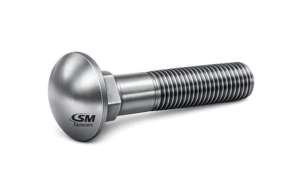
Carriage Bolt
1 — INDUSTRY CONTEXT, TECHNICAL DEFINITION & JOINT ENGINEERING
1.1 Industry Context
Carriage bolts represent a specialized fastening solution designed primarily for non-rotational installation environments, where access to only one side of the joint is possible or where exposed threads must remain secure against tampering.
Across global industrial sectors, carriage bolts are extensively utilized in:
- Structural steel secondary connections
- Transmission tower assemblies
- Rail infrastructure
- Conveyor and material handling systems
- Heavy equipment guarding systems
- Timber-to-steel structural connections
- Petrochemical platforms using composite panels
- Offshore deck equipment and grating assemblies
Unlike hex bolts or structural bolts, carriage bolts rely on geometry-driven anti-rotation locking rather than tool engagement at the head.
For EPC contractors and mechanical engineers, carriage bolts serve as:
✔ Semi-structural fastening elements
✔ Anti-tamper exterior fasteners
✔ Load-transferring shear connectors
✔ Alignment-maintaining joint fasteners
SM Fasteners manufactures carriage bolts under controlled ISO 9001 quality systems, supporting global infrastructure, industrial fabrication, and export-grade assemblies.
1.2 Technical Definition
A Carriage Bolt is defined as:
A round-head bolt featuring a square neck beneath the head that embeds into softer material or pre-formed square holes to prevent rotation during tightening.
Fundamental Characteristics
| Feature | Engineering Function |
|---|---|
| Domed Round Head | Smooth external surface, safety & aesthetics |
| Square Neck | Anti-rotation locking mechanism |
| Threaded Shank | Generates clamping force |
| Partial/Full Thread | Load distribution control |
| Nut Tightening | Single-sided installation |
Unlike hex bolts, torque is applied exclusively at the nut side.
1.3 Functional Role in Assemblies
Carriage bolts are selected where:
- Bolt head must remain flush or tamper-resistant
- Surface snagging must be avoided
- Aesthetic or safety requirements exist
- Repetitive vibration environments demand anti-rotation stability
Typical joint configuration:
1.4 Load Mechanics & Force Behavior
Primary Load Modes
| Load Type | Carriage Bolt Response |
|---|---|
| Tensile Load | Carried by threaded section |
| Shear Load | Supported by shank diameter |
| Clamp Load | Generated via nut tightening |
| Bearing Load | Transferred through square neck |
| Fatigue Load | Influenced by preload stability |
Load Transfer Mechanism
Carriage bolts function primarily as bearing-type fasteners rather than slip-critical structural bolts.
The square neck transfers torque resistance into the joint material:
Proper seating of the square neck is essential.
1.5 Preload and Clamping Force Principles
Bolt preload creates frictional resistance between joint members.
Preload Equation
Where:
- F = Preload force (N)
- T = Applied torque (Nm)
- K = Nut factor (0.16–0.22 typical)
- D = Nominal diameter (m)
Worked Example
M12 Carriage Bolt — Property Class 8.8
- Torque = 80 Nm
- Nut factor = 0.18
- Diameter = 0.012 m
Resulting preload ≈ 37 kN
1.6 Torque–Tension Relationship
Preload depends heavily on friction:
| Condition | Nut Factor K |
|---|---|
| Dry steel | 0.20–0.22 |
| Zinc plated | 0.18 |
| Lubricated | 0.16 |
| PTFE coated | 0.14–0.15 |
Approximately 85–90% of torque is lost to friction.
1.7 Joint Design Principles
Engineer Selection Criteria
| Design Parameter | Requirement |
|---|---|
| Hole Geometry | Square recess or deformable material |
| Material Hardness | Joint softer than bolt neck |
| Grip Length | Match unthreaded shank |
| Clamp Load | Prevent joint separation |
| Corrosion Exposure | Select coating/material |
| Inspection Access | Nut-side accessibility |
Recommended Joint Practice
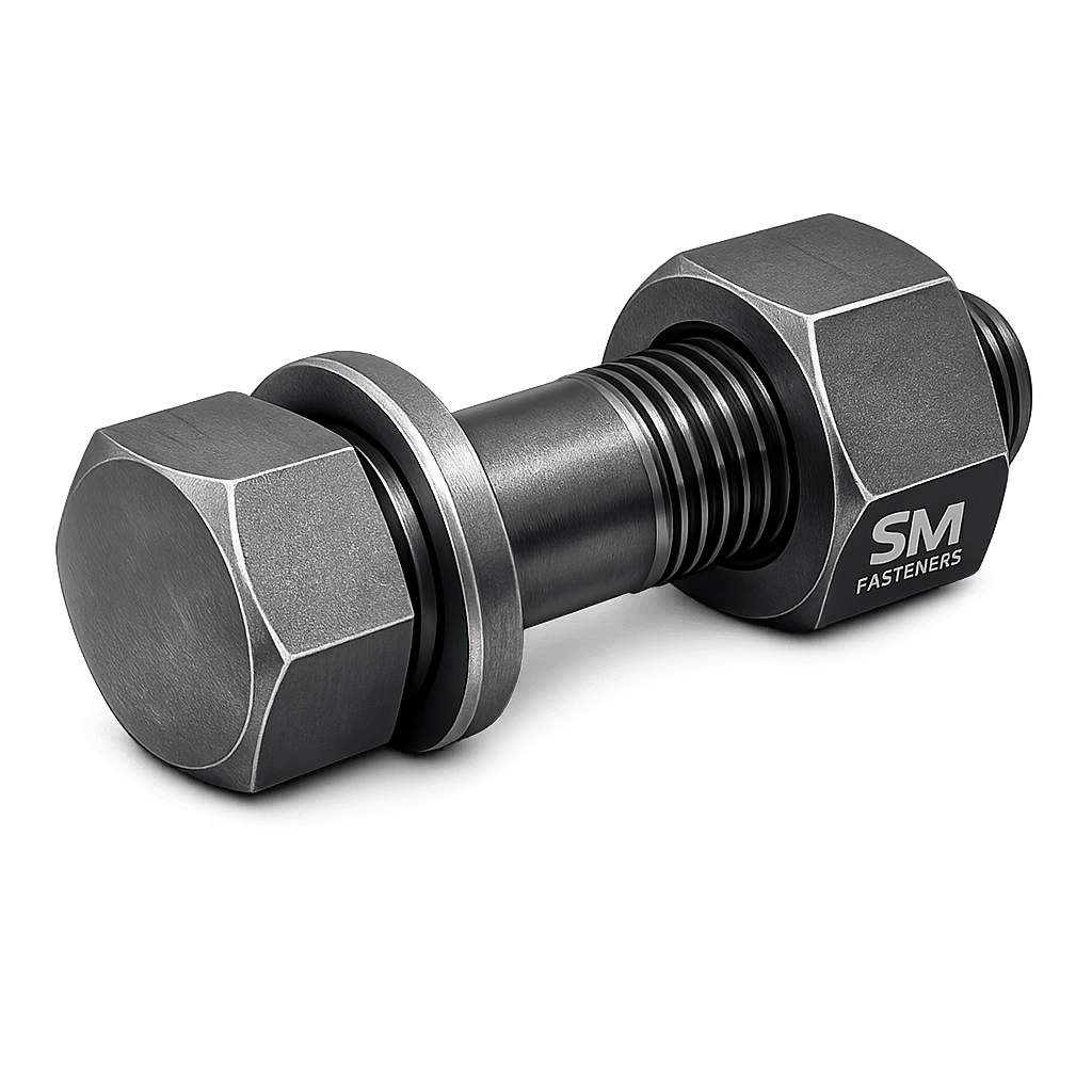
✔ Washer under nut
✔ Full square neck engagement
✔ Avoid hardened steel mating surfaces without square recess
✔ Maintain minimum thread engagement = 1 × diameter
1.8 Thread Engagement & Load Distribution
Minimum engagement:
Critical for preventing:
- Thread stripping
- Fatigue cracking
- Joint relaxation
1.9 Failure Mechanisms
1.9.1 Shear Failure
Occurs when lateral forces exceed shear capacity.
1.9.2 Fatigue Failure
Caused by:
- Insufficient preload
- Vibration
- Cyclic loading
Mitigation:
- Proper torque control
- Hardened washers
- Controlled friction coefficient
1.9.3 Square Neck Spin-Out
Common carriage bolt failure.
Causes:
- Over-sized hole
- Hard mating material
- Poor installation
Engineering solution:
- Correct hole tolerance
- Serrated or rib-neck variants
1.9.4 Hydrogen Embrittlement
Applicable to high-strength (>1000 MPa) bolts with electroplating.
SM Fasteners applies controlled baking procedures per ISO requirements.
1.9.5 Stress Corrosion Cracking
Critical environments:
- Offshore marine
- H₂S exposure
- Chloride environments
Material upgrade required:
- Duplex
- Super Duplex
- Nickel alloys
1.10 Carriage Bolt vs Other Bolts
| Bolt Type | Tooling | Anti-Rotation | Typical Use |
|---|---|---|---|
| Carriage Bolt | Nut side only | Square neck | Timber/structures |
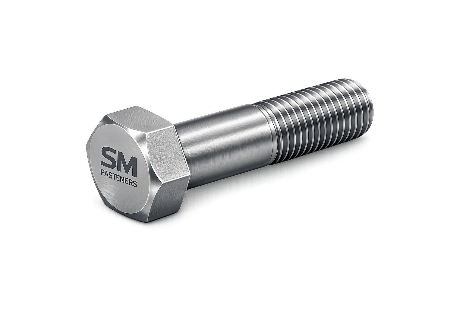
| Hex bolt | Both sides | No | Machinery |
| Structural Bolt | Controlled tension | No | Steel structures |
| Elevator Bolt | Flat head | Limited | Conveyors |
1.11 Engineering Advantages
- Smooth exposed surface
- Reduced injury risk
- Tamper resistance
- Fast installation
- Reliable shear transfer
1.12 SM Fasteners Engineering Integration
SM Fasteners supplies carriage bolts engineered for:
- ISO global interchangeability
- EPC procurement compliance
- Traceable manufacturing batches
- Advanced alloy material availability
- Custom square-neck geometries
Manufacturing aligns with:
✔ ISO 9001 Quality Systems
✔ UKAF-aligned verification
✔ MSME certified production capability
2. PRODUCT TYPES, DIMENSIONAL LOGIC & INTERNATIONAL STANDARDS
2.1 Carriage Bolt Product Classification
Carriage bolts are engineered in multiple configurations to satisfy varying load requirements, installation environments, joint materials, and industry specifications.
Unlike general-purpose bolts, geometry variation directly influences anti-rotation performance, bearing load transfer, and long-term joint reliability.
Primary Functional Variants
| Type | Description | Engineering Purpose | Typical Industries |
|---|---|---|---|
| Standard Carriage Bolt | Round head + square neck | General structural fastening | Construction, infrastructure |
| Short Neck Carriage Bolt | Reduced square height | Thin materials | Sheet metal assemblies |
| Rib Neck Carriage Bolt | Serrated neck | Hard material anti-spin | Automotive, equipment |
| Fin Neck Carriage Bolt | Radial fins below head | High torque resistance | Machinery guards |
| Dome Head Carriage Bolt | Large smooth head | Safety exposure areas | Rail, public structures |
| Mushroom Head Bolt | Oversized bearing head | Soft timber joints | Bridges, wooden structures |
| Fully Threaded Carriage Bolt | Threads entire length | Variable grip applications | OEM assemblies |
| Partial Thread Carriage Bolt | Smooth shank | Improved shear strength | Structural joints |
| Stainless Carriage Bolt | Corrosion resistant | Marine & chemical service | Offshore & petrochemical |
| PEEK Carriage Bolt | Polymer engineered | Electrical isolation | Electronics, chemical plants |
SM Fasteners manufactures both standardized and custom-engineered geometries to meet EPC drawings and OEM specifications.
2.2 Dimensional Logic & Geometry Engineering
Carriage bolt geometry is governed by:
- Head bearing surface requirements
- Square neck torque resistance
- Thread engagement length
- Load transfer efficiency
Key Geometric Elements
| Parameter | Symbol | Function |
|---|---|---|
| Nominal Diameter | d | Determines tensile capacity |
| Thread Pitch | P | Load distribution |
| Head Diameter | dk | Bearing area |
| Head Height | k | Surface stability |
| Square Neck Width | s | Anti-rotation locking |
| Square Neck Height | v | Torque resistance |
| Thread Length | b | Clamping capability |
| Overall Length | L | Grip accommodation |
2.3 Standard Dimensional Specification Table (Metric Series)
(Aligned with ISO 8677 / DIN 603)
| Size | Pitch (mm) | Head Dia dk (mm) | Head Height k (mm) | Square Neck s (mm) | Neck Height v (mm) | Standard Length Range (mm) |
|---|---|---|---|---|---|---|
| M6 | 1.0 | 16 | 3.3 | 6.5 | 4.1 | 16–120 |
| M8 | 1.25 | 20 | 4.4 | 8.5 | 4.7 | 20–150 |
| M10 | 1.5 | 24 | 5.4 | 10.5 | 5.6 | 25–200 |
| M12 | 1.75 | 30 | 6.5 | 12.5 | 6.8 | 30–300 |
| M16 | 2.0 | 38 | 8.0 | 16.5 | 8.8 | 40–350 |
| M20 | 2.5 | 46 | 10.0 | 20.5 | 11.5 | 50–400 |
| M24 | 3.0 | 58 | 12.0 | 24.5 | 14.0 | 60–450 |
SM Fasteners maintains dimensional verification through calibrated inspection systems compliant with ISO 9001 procedures.
2.4 Imperial Dimensional Series (UNC/UNF)
| Size | Thread | Head Dia (in) | Square Neck (in) | Length Range (in) |
|---|---|---|---|---|
| 1/4″ | UNC | 0.625 | 0.260 | 1–5 |
| 5/16″ | UNC | 0.719 | 0.323 | 1–6 |
| 3/8″ | UNC | 0.875 | 0.385 | 1–8 |
| 1/2″ | UNC | 1.187 | 0.510 | 1.5–10 |
| 5/8″ | UNC | 1.469 | 0.635 | 2–12 |
| 3/4″ | UNC | 1.750 | 0.760 | 2–14 |
2.5 Thread Forms & Tolerances
Carriage bolts support global interchangeability through standardized thread systems.
Thread Standards Table
| Standard | Thread Form | Typical Region | Tolerance Class |
|---|---|---|---|
| ISO Metric | M | Global | 6g |
| UNC | Unified Coarse | USA/Canada | 2A |
| UNF | Unified Fine | Precision equipment | 2A |
| BSW | British Standard Whitworth | Legacy UK | Medium |
| BSF | British Standard Fine | Machinery | Close fit |
SM Fasteners supplies threads verified using:
- GO/NO-GO gauges
- Optical profile measurement
- SPC-controlled rolling processes
2.6 Applicable International Standards
Carriage bolts are governed by multiple global standards depending on project specifications.
Primary Standards
| Standard | Description |
|---|---|
| DIN 603 | Round head square neck bolts |
| ISO 8677 | Metric carriage bolts |
| ISO 8678 | Reduced neck carriage bolts |
| ASTM A307 | Carbon steel bolts |
| ASTM F593 | Stainless steel bolts |
| ASME B18.5 | Inch carriage bolts |
| BS 4933 | British carriage bolt specification |
| EN ISO 898-1 | Mechanical properties |
| ISO 965 | Thread tolerances |
Interchangeability Considerations
| Parameter | ISO vs ASTM |
|---|---|
| Head geometry | Slight variation |
| Thread tolerance | Compatible |
| Mechanical properties | Grade dependent |
| Fit-up | Generally interchangeable |
Engineering verification is recommended for EPC critical assemblies.
2.7 Mechanical Property Classes
Property class selection governs load capability.
Mechanical Property Table
| Property Class | Yield Strength (MPa) | Tensile Strength (MPa) | Typical Use |
|---|---|---|---|
| 4.6 | 240 | 400 | Light assemblies |
| 5.8 | 400 | 500 | Timber structures |
| 8.8 | 640 | 800 | Industrial structures |
| 10.9 | 900 | 1000 | Heavy equipment |
| 12.9* | 1080 | 1200 | Special engineered use |
(*Rare for carriage bolts due to neck deformation requirements.)
2.8 Proof Load & Tensile Strength Table
| Size | Grade 5.8 Proof Load (kN) | Grade 8.8 Proof Load (kN) | Ultimate Tensile (kN) |
|---|---|---|---|
| M8 | 14 | 22 | 28 |
| M10 | 22 | 35 | 45 |
| M12 | 32 | 50 | 65 |
| M16 | 58 | 91 | 118 |
| M20 | 91 | 142 | 184 |
| M24 | 131 | 205 | 265 |
Values aligned with ISO 898-1 calculations.
2.9 Dimensional Tolerances & Fit Control
Critical tolerances influencing installation:
| Feature | Typical Tolerance |
|---|---|
| Shank diameter | h9 |
| Square neck width | +0 / −0.1 mm |
| Head diameter | ±0.3 mm |
| Thread pitch | ISO tolerance class |
| Straightness | ≤0.2% of length |
SM Fasteners maintains traceability through batch inspection and calibration records.
2.10 Geometry Influence on Load Performance
Square Neck Engagement
Torque resistance:
Where r equals half the square width.
Greater square width → improved anti-rotation capacity.
Head Bearing Area
Larger heads reduce:
- Embedment
- Surface crushing
- Joint relaxation
2.11 Weight Chart — Carriage Bolts
(Typical carbon steel density basis — aligned with SM Fasteners manufacturing data)
| Size | Length (mm) | Weight/Piece (kg) | Weight/100 pcs (kg) |
|---|---|---|---|
| M8 | 40 | 0.020 | 2.0 |
| M10 | 50 | 0.038 | 3.8 |
| M12 | 60 | 0.070 | 7.0 |
| M16 | 80 | 0.165 | 16.5 |
| M20 | 100 | 0.325 | 32.5 |
| M24 | 120 | 0.580 | 58.0 |
Weight verification supports EPC logistics planning and export packing calculations.
2.12 Engineering Selection Logic
Engineers typically select carriage bolts using:
- Load requirement
- Joint material hardness
- Corrosion environment
- Installation accessibility
- Applicable project standard
- Inspection requirement
2.13 SM Fasteners Dimensional Manufacturing Capability
SM Fasteners supports:
- Metric & Imperial production
- Custom square neck dimensions
- Special head diameters
- Non-standard lengths
- PEEK carriage bolt engineering
- Project-specific tolerances
Production controlled under:
✔ ISO 9001 certified procedures
✔ UKAF-aligned inspection framework
✔ Full traceability and batch documentation
3. MATERIAL ENGINEERING, HEAT TREATMENT, MANUFACTURING WORKFLOW & SURFACE ENGINEERING
3.1 Materials Engineering Philosophy for Carriage Bolts
Material selection is the most critical engineering decision affecting:
- Load carrying capability
- Corrosion resistance
- Temperature performance
- Fatigue life
- Installation reliability
- Compliance with EPC project specifications
Carriage bolts operate frequently in mixed-material joints (timber, composites, structural steel, equipment frames). Therefore, materials must provide:
✔ Controlled hardness
✔ Adequate ductility for square neck embedding
✔ High clamp retention
✔ Environmental durability
SM Fasteners manufactures carriage bolts across a complete industrial alloy spectrum under ISO 9001 quality management systems.
3.2 Industrial Material Range
Standard Metallic Materials
| Material Family | Common Grades | Characteristics | Typical Applications |
|---|---|---|---|
| Carbon Steel | ASTM A307, Grade 4.6–8.8 | Economical, good strength | Construction & infrastructure |
| Alloy Steel | 10.9, 12.9 | High strength | Heavy equipment |
| Stainless Steel | A2-70, A4-80 | Corrosion resistant | Marine & chemical |
| Duplex Stainless | 2205 | High strength + chloride resistance | Offshore |
| Super Duplex | 2507 | Extreme corrosion resistance | Oil & gas |
| Nickel Alloys | Monel 400 | Seawater resistant | Marine hardware |
| Inconel | 625 / 718 | High temperature | Power & LNG |
| Incoloy | 825 | Acid resistance | Chemical plants |
| Hastelloy | C276 | Aggressive chemicals | Refinery processing |
| SMO 254 | 6Mo stainless | Chloride resistance | Desalination |
| Nickel | Commercial Nickel | Chemical stability | Specialty equipment |
Advanced Polymer Materials
PEEK Carriage Bolts
SM Fasteners manufactures precision PEEK (Polyether Ether Ketone) carriage bolts for specialized industries.
| Property | Value |
|---|---|
| Continuous Service Temp | 250°C |
| Chemical Resistance | Excellent |
| Electrical Insulation | Outstanding |
| Weight Reduction | ~70% lighter than steel |
| Magnetic Neutrality | Yes |
Applications
- Semiconductor manufacturing
- Chemical processing
- Offshore electrical isolation
- Hydrogen systems
- Medical equipment
3.3 Material Comparison Table
| Material | UTS (MPa) | Yield (MPa) | Corrosion Resistance | Temperature Limit | Relative Cost | Typical Industry |
|---|---|---|---|---|---|---|
| Carbon Steel | 400–800 | 240–640 | Low | 300°C | Low | Construction |
| Alloy Steel | 900–1200 | 850+ | Moderate | 400°C | Medium | Heavy equipment |
| SS 304 | 700 | 450 | Good | 870°C | Medium | General industry |
| SS 316 | 800 | 550 | Very Good | 870°C | Medium-High | Marine |
| Duplex 2205 | 900 | 650 | Excellent | 300°C | High | Offshore |
| Super Duplex | 1000 | 750 | Extreme | 300°C | Very High | Oil & gas |
| Monel 400 | 550 | 240 | Seawater resistant | 480°C | Very High | Marine |
| Inconel 625 | 1000 | 700 | Extreme | 980°C | Premium | LNG/Power |
| SMO 254 | 680 | 300 | Chloride resistant | 400°C | Premium | Desalination |
| PEEK | — | — | Chemical resistant | 250°C | High | Electronics |
3.4 Corrosion Resistance vs Environment
| Environment | Carbon Steel | SS304 | SS316 | Duplex | Super Duplex | Nickel Alloys | PEEK |
|---|---|---|---|---|---|---|---|
| Indoor Industrial | ✓ | ✓ | ✓ | ✓ | ✓ | ✓ | ✓ |
| Marine Atmosphere | ✗ | △ | ✓ | ✓✓ | ✓✓ | ✓✓ | ✓ |
| Seawater Immersion | ✗ | ✗ | △ | ✓ | ✓✓ | ✓✓ | ✓ |
| Chloride Exposure | ✗ | △ | ✓ | ✓✓ | ✓✓ | ✓✓ | ✓ |
| H₂S / Sour Service | ✗ | △ | ✓ | ✓✓ | ✓✓ | ✓✓ | ✓ |
| Acidic Chemical | ✗ | △ | ✓ | ✓ | ✓✓ | ✓✓ | ✓✓ |
| Cryogenic | ✓ | ✓ | ✓ | ✓ | ✓ | ✓✓ | ✓ |
| Electrical Isolation | ✗ | ✗ | ✗ | ✗ | ✗ | ✗ | ✓✓ |
Legend: ✓✓ Excellent | ✓ Suitable | △ Limited | ✗ Not Recommended
Materials supplied by SM Fasteners can comply with NACE MR0175 / ISO 15156 where required.
3.5 Mechanical Property Requirements
Carriage bolts require balanced hardness to allow square neck deformation without fracture.
Mechanical Properties Table (ISO 898-1)
| Property Class | Tensile Strength (MPa) | Yield Strength (MPa) | Hardness (HB) |
|---|---|---|---|
| 4.6 | 400 | 240 | 120–220 |
| 5.8 | 500 | 400 | 150–240 |
| 8.8 | 800 | 640 | 220–300 |
| 10.9 | 1000 | 900 | 300–380 |
Excess hardness may cause neck cracking during installation.
3.6 Heat Treatment Processes
Heat treatment determines final mechanical performance.
3.6.1 Annealing
- Improves machinability
- Relieves forming stresses
- Used before cold heading
3.6.2 Quenching & Tempering
Primary strengthening process.
Steps:
- Austenitizing
- Rapid quenching
- Tempering
Produces:
- High tensile strength
- Improved fatigue resistance
3.6.3 Normalizing
Refines grain structure for carbon steels.
3.6.4 Solution Annealing (Stainless Steel)
- Restores corrosion resistance
- Eliminates carbide precipitation
3.6.5 Hydrogen Embrittlement Relief Baking
Mandatory for plated high-strength bolts.
Typical condition:
- 200°C bake
- 2–24 hours depending on grade
SM Fasteners controls baking under ISO 9001 documented procedures.
3.7 Hardness Limits for Sour Service
| Requirement | Value |
|---|---|
| NACE MR0175 Hardness Limit | ≤22 HRC |
| Typical Grade Used | 8.8 equivalent |
| Inspection Method | Rockwell C testing |
Prevents sulfide stress cracking.
3.8 End-to-End Manufacturing Workflow
SM Fasteners follows a controlled manufacturing chain ensuring traceability and repeatability.
Step 1 — Raw Material Procurement
- Approved steel mills
- Heat number traceability
- EN 10204 3.1 Mill Test Certificate verification
- Chemical composition confirmation
Step 2 — Incoming Material Inspection
- Spectrometer PMI verification
- Diameter & surface checks
- Inclusion inspection
Step 3 — Cutting & Preparation
Wire rod cut into slugs.
Step 4 — Cold Heading / Hot Forging
Forms:
- Round head
- Square neck
Benefits:
- Grain flow continuity
- Higher fatigue resistance
- Minimal material waste
Step 5 — Trimming & Neck Calibration
Ensures precise anti-rotation geometry.
Step 6 — Thread Formation
Thread Rolling (Preferred)
Advantages:
- Increased fatigue strength
- Compressive surface stresses
- Smooth finish
Thread cutting used only for special alloys.
Step 7 — Heat Treatment
Controlled furnace cycles with batch recording.
Step 8 — Surface Preparation
- Shot blasting
- Pickling
- Cleaning
Step 9 — Surface Coating
Applied per customer specification.
Step 10 — Final Inspection & Traceability
- Dimensional verification
- Mechanical testing
- Batch marking
- Documentation release
3.9 Surface Engineering & Coatings
Surface treatments extend service life and reduce installation friction.
Surface Finish Comparison Table
| Coating | Thickness | Corrosion Resistance | Friction | Typical Use |
|---|---|---|---|---|
| Plain Oil Finish | Minimal | Low | Medium | Indoor use |
| Zinc Electroplated | 5–12 µm | Moderate | Low | General industry |
| Hot Dip Galvanized | 40–80 µm | High | Higher torque | Structural |
| Mechanical Galvanized | 15–30 µm | Good | Controlled | Transport |
| Zinc Flake (Geomet/Dacromet) | 8–12 µm | Excellent | Stable | Automotive |
| PTFE Coated | Thin | Excellent | Very low | Chemical plants |
| Xylan | Thin | Excellent | Anti-galling | Offshore |
| Nickel Plating | Decorative/Corrosion | Moderate | Low | Equipment |
| Passivation (SS) | — | Restores corrosion resistance | Neutral | Stainless bolts |
SM Fasteners validates coating thickness via calibrated gauges.
3.10 Coating Selection vs Environment
| Environment | Recommended Finish |
|---|---|
| Indoor Machinery | Zinc plated |
| Outdoor Structures | HDG |
| Marine Offshore | SS316 / Duplex |
| Chemical Processing | PTFE/Xylan |
| Automotive | Zinc flake |
| High Temperature | Nickel alloy / Plain |
| Electrical Isolation | PEEK |
3.11 Friction Control & Torque Stability
Surface finish directly affects preload accuracy.
Where coating determines nut factor K.
Consistent coatings enable predictable torque–tension relationships required in EPC installations.
3.12 SM Fasteners Manufacturing Capability Integration
SM Fasteners supports:
- Custom alloy sourcing
- Project-specific heat treatment cycles
- NACE compliant materials
- PEEK precision machining
- Controlled coating partnerships
- Full traceability from raw material to dispatch
Manufacturing operates under:
✔ ISO 9001 Quality Management
✔ UKAF-aligned auditing practices
✔ MSME certified industrial production
4. INSPECTION, QUALITY CONTROL, APPLICATION ENGINEERING & GLOBAL EXPORT READINESS
4.1 Quality Philosophy — Carriage Bolt Manufacturing
Carriage bolts used in industrial assemblies must demonstrate:
- Dimensional conformity
- Verified mechanical performance
- Traceable metallurgy
- Consistent preload behavior
- Environmental durability
SM Fasteners integrates inspection and verification throughout production in accordance with ISO 9001 certified quality management systems, ensuring suitability for EPC, OEM, infrastructure, and energy-sector procurement.
4.2 Inspection & Quality Control Workflow
Quality assurance begins before manufacturing and continues through shipment release.
Inspection Stages
| Stage | Inspection Activity | Objective |
|---|---|---|
| Raw Material | Chemical verification | Material conformity |
| Incoming Inspection | Diameter & surface checks | Defect elimination |
| In-Process | Forging geometry inspection | Neck accuracy |
| Thread Inspection | GO/NO-GO gauging | Fit control |
| Heat Treatment | Hardness verification | Mechanical compliance |
| Coating Inspection | Thickness measurement | Corrosion protection |
| Final Inspection | Dimensional + visual | Release approval |
| Pre-Dispatch | Documentation review | Traceability |
4.3 Dimensional Inspection Requirements
Critical carriage bolt dimensions requiring verification:
| Feature | Inspection Method |
|---|---|
| Head diameter | Digital caliper |
| Head height | Height gauge |
| Square neck width | Micrometer |
| Square neck height | Optical comparator |
| Shank diameter | Micrometer |
| Thread pitch | Thread gauge |
| Straightness | V-block inspection |
| Overall length | Caliper measurement |
SM Fasteners maintains calibrated equipment traceable to international standards.
4.4 Mechanical Testing Requirements
Mandatory Mechanical Tests
| Test | Standard | Purpose |
|---|---|---|
| Tensile Test | ISO 898-1 | Strength verification |
| Proof Load Test | ISO 898 | Elastic behavior |
| Hardness Test | ISO 6508 | Heat treatment validation |
| Wedge Tensile Test | ISO | Head integrity |
| Impact Test (if required) | ASTM | Low-temperature service |
| Elongation Test | ISO | Ductility verification |
4.5 Non-Destructive Testing (NDT)
Applied for critical industrial or offshore projects.
| Method | Detection Capability |
|---|---|
| Magnetic Particle Inspection | Surface cracks |
| Dye Penetrant Testing | Fine surface defects |
| Ultrasonic Testing | Internal flaws |
| Eddy Current Testing | Material discontinuity |
| Visual Inspection | Surface defects |
4.6 Positive Material Identification (PMI)
For alloy and corrosion-resistant materials.
Verification methods:
- XRF Spectrometry
- Optical Emission Spectroscopy
Ensures supplied material matches project specification.
4.7 Certification & Documentation
SM Fasteners supports full industrial documentation packages.
Standard Documentation Set
| Document | Description |
|---|---|
| EN 10204 3.1 MTC | Chemical & mechanical certification |
| EN 10204 3.2 | Third-party inspection |
| Heat Treatment Report | Furnace cycle records |
| Dimensional Inspection Report | Measurement verification |
| Coating Thickness Report | Corrosion protection validation |
| PMI Report | Alloy confirmation |
| Certificate of Conformity (CoC) | Compliance declaration |
| Packing List | Export logistics |
| Traceability Record | Batch identification |
4.8 Tightening Torque Chart
(Typical values — Carbon Steel Property Class 8.8)
| Size | Dry Torque (Nm) | Zinc Plated (Nm) | Lubricated (Nm) |
|---|---|---|---|
| M6 | 10 | 9 | 8 |
| M8 | 25 | 22 | 20 |
| M10 | 49 | 44 | 40 |
| M12 | 85 | 80 | 70 |
| M16 | 210 | 190 | 170 |
| M20 | 410 | 370 | 330 |
| M24 | 710 | 640 | 580 |
Actual torque values depend on lubrication and coating condition.
4.9 Preload Calculation — Engineering Table
Formula
Where:
- F = Preload Force
- T = Torque
- K = Nut Factor
- D = Bolt Diameter
Example Calculation — M16 Carriage Bolt (Grade 8.8)
- Torque = 210 Nm
- Nut factor = 0.18
- Diameter = 0.016 m
4.10 Thread Standards & Tolerances Table
| Thread Type | Standard | Tolerance |
|---|---|---|
| Metric Coarse | ISO 261 | 6g |
| Metric Fine | ISO 965 | 6g |
| UNC | ASME B1.1 | 2A |
| UNF | ASME B1.1 | 2A |
| BSW | BS 84 | Medium |
| BSF | BS 84 | Close |
4.11 Failure Prevention Through Inspection
| Failure Mode | Inspection Control |
|---|---|
| Neck Spin-Out | Square dimension check |
| Fatigue Failure | Surface inspection |
| Hydrogen Embrittlement | Baking verification |
| Thread Galling | Surface finish control |
| Stress Corrosion | Material verification |
4.12 Industry Application Mapping
Construction & Structural Steel
- Timber framing
- Guard rails
- Bridges
- Structural cladding
Oil & Gas Industry
Upstream
- Platform walkways
- Equipment guards
Midstream
- Pipeline supports
- Compressor stations
Downstream
- Refinery platforms
- Access systems
Duplex and nickel alloys selected where corrosion risk exists.
Power Generation
- Turbine housing guards
- Cable tray supports
- Cooling tower structures
Petrochemical & Chemical Processing
- Chemical tanks
- Pump bases
- Polymer plant equipment
PEEK carriage bolts used where electrical isolation is required.
LNG & Offshore
- Deck fittings
- Safety barriers
- Marine access structures
Materials:
- SS316
- Duplex
- Super Duplex
- Inconel
Automotive & Heavy Equipment
- Trailer bodies
- Agricultural machinery
- Conveyor systems
Railways & Infrastructure
- Signal structures
- Noise barriers
- Platform assemblies
Shipbuilding & Marine
- Deck equipment
- Interior fittings
- Composite structures
4.13 Weight Reference Chart (Engineering Logistics Table)
| Size | Length | Weight/Piece (kg) | Weight/100 pcs (kg) |
|---|---|---|---|
| M8 × 40 | 0.020 | 2.0 | |
| M10 × 50 | 0.038 | 3.8 | |
| M12 × 60 | 0.070 | 7.0 | |
| M16 × 80 | 0.165 | 16.5 | |
| M20 × 100 | 0.325 | 32.5 | |
| M24 × 120 | 0.580 | 58.0 |
Aligned with SM Fasteners production data for export calculations.
4.14 Packaging & Preservation for Export
Industrial carriage bolts require protection against:
- Moisture
- Mechanical damage
- Thread contamination
- Corrosion during transit
Standard Packaging Methods
| Method | Purpose |
|---|---|
| VCI Packaging | Corrosion prevention |
| Thread Protectors | Prevent damage |
| Heat-sealed bags | Moisture barrier |
| HDPE drums | Bulk shipment |
| Wooden crates | Heavy export orders |
Export Compliance
- ISPM-15 fumigated wooden crates
- Container moisture control
- Barcode traceability labeling
4.15 Global Export Capability — SM Fasteners
SM Fasteners supports international project supply including:
- EPC contractors
- OEM manufacturers
- Global distributors
- Infrastructure megaprojects
Capabilities include:
✔ Metric & Imperial manufacturing
✔ Custom drawings production
✔ Exotic alloy sourcing
✔ PEEK precision fasteners
✔ Batch traceability systems
✔ Inspection witness support
4.16 Procurement Readiness for EPC Projects
Typical procurement submission includes:
- Technical datasheet
- GA dimensional drawing
- Material certificates
- Inspection test plan (ITP)
- Quality plan
- Packing specification
- Compliance statement
4.17 Integrated ISO 9001 Quality System
SM Fasteners applies ISO 9001 principles across:
- Supplier qualification
- Manufacturing control
- Calibration management
- Corrective action systems
- Continuous improvement
- Customer traceability support
UKAF-aligned auditing ensures international quality recognition.
4.18 Engineering Selection Summary
Carriage Bolt Selection Matrix
| Requirement | Recommended Choice |
|---|---|
| Timber structure | Carbon steel HDG |
| Marine exposure | SS316 / Duplex |
| Chemical plant | PTFE coated / Nickel alloy |
| High strength | Property class 8.8 |
| Electrical isolation | PEEK carriage bolt |
| Outdoor infrastructure | Hot dip galvanized |
4.19 Engineering Advantages of SM Fasteners Carriage Bolts
- Precision square-neck forming
- Controlled thread rolling
- Verified heat treatment
- Advanced alloy capability
- Global standards compliance
- Export-ready packaging systems
All production aligned with:
ISO 9001 Certified Manufacturing
MSME Industrial Capability
UKAF Quality Framework