Serrated Flange Bolt
1. Industry Context

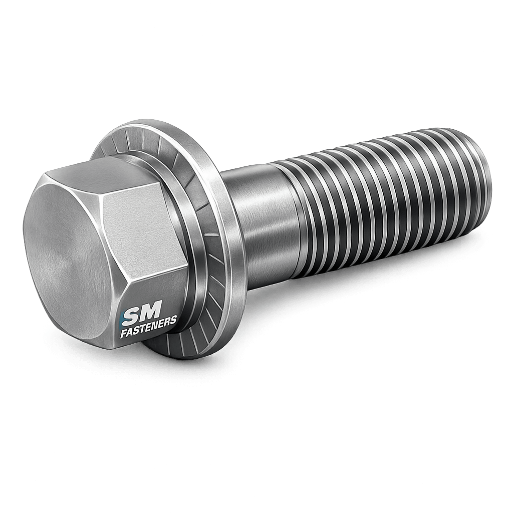
Serrated flange bolts are engineered fastening elements developed to improve joint reliability under vibration, cyclic loading, and dynamic service environments. They integrate a washer-like flange with radial serrations beneath the head, eliminating the need for separate locking washers while increasing resistance to loosening.
Across modern heavy industries, bolted joints must satisfy increasingly stringent requirements:
- High vibration resistance
- Reduced assembly time
- Controlled preload retention
- Repeatable torque performance
- Reduced component count
- Reliable field maintenance
Industries adopting serrated flange bolts include:
| Industry | Functional Requirement |
|---|---|
| Structural Steel | Slip-resistant structural joints |
| Oil & Gas | Vibration & pressure cycling resistance |
| Power Plants | Thermal expansion stability |
| Automotive & Heavy Equipment | High-cycle fatigue resistance |
| Railways | Anti-loosening safety assemblies |
| Petrochemical Plants | Maintenance-friendly bolting |
| Shipbuilding | Corrosion + vibration tolerance |
SM Fasteners manufactures serrated flange bolts engineered for EPC, OEM, and infrastructure projects requiring certified, traceable fastening systems compliant with international standards.
2. Technical Definition
A Serrated Flange Bolt is defined as:
A hex head bolt incorporating an integral circular flange with radial serrations on the bearing surface designed to increase frictional locking and prevent rotational loosening under dynamic loads.
Key Structural Elements
| Component | Function |
|---|---|
| Hex Head | Torque transmission |
| Integral Flange | Load distribution |
| Serrations | Mechanical locking action |
| Threaded Shank | Tensile load transfer |
| Bearing Face | Friction interface |
Unlike standard hex bolts requiring washers or lock washers, the serrated flange performs three simultaneous functions:
- Clamp load distribution
- Anti-rotation locking
- Surface embedding resistance
3. Functional Role in Bolted Assemblies
Serrated flange bolts are selected when:
- Vibration loosening risk exists
- Assembly speed must be optimized
- Washer loss is unacceptable
- Joint slip must be minimized
- Torque repeatability is required
Typical joint configuration:
4. Load Mechanics & Force Behavior
Bolted joints function as preloaded spring systems.
Fundamental Principle
A bolt behaves elastically when tightened.
Applied torque → Bolt elongation → Clamp force → Joint integrity.
4.1 Forces Acting on Serrated Flange Bolts
| Force Type | Description |
|---|---|
| Tensile Load | Axial separation forces |
| Shear Load | Lateral movement forces |
| Clamp Load | Compression between members |
| Frictional Resistance | Generated by serrations |
| Dynamic Load | Vibration/impact forces |
The flange increases the bearing area, reducing localized compressive stresses.
4.2 Torque–Tension Relationship
Preload equation:
Where:
- F = Preload force (N)
- T = Applied torque (Nm)
- K = Nut factor (0.10–0.25)
- D = Nominal diameter (m)
Typical nut factors:
| Condition | Nut Factor (K) |
|---|---|
| Dry | 0.20–0.25 |
| Zinc plated | 0.18 |
| Lubricated | 0.12–0.16 |
| PTFE coated | 0.10–0.12 |
Serrations increase friction variability; therefore torque calibration is essential for critical assemblies.
4.3 Clamp Force Development
Preload must exceed external separating loads.
Recommended Engineering Rule
Benefits:
- Prevents joint separation
- Minimizes fatigue failure
- Maintains friction grip
5. Joint Design Principles
5.1 Bearing Pressure Distribution
Flange bolts reduce:
- Surface indentation
- Washer misalignment
- Local yielding
Flange diameter typically equals 1.6–2.0 × bolt diameter.
5.2 Anti-Loosening Mechanism
Serrations create:
- Micro mechanical interlock
- Increased rotational resistance
- Enhanced vibration stability
Important engineering note:
⚠ Serrated flange bolts should not be used on:
- Soft materials (aluminum, composites)
- Painted precision surfaces
- Hardened mating faces where serrations cannot embed
5.3 Friction Grip Joint Behavior
Joint strength is primarily governed by friction:
Where:
- μ = friction coefficient.
Serrations increase effective friction coefficient at the interface.
5.4 Thread Engagement Requirements
Minimum engagement:
| Material | Engagement Length |
|---|---|
| Steel | 1 × diameter |
| Aluminum | 1.5 × diameter |
| Cast Iron | 1.25 × diameter |
5.5 Failure Mechanisms
1. Fatigue Failure
Occurs from preload loss or fluctuating stress.
Mitigation:
- Proper torque control
- Correct property class selection
2. Shear Failure
Occurs when joint slip happens.
Prevention:
- Adequate preload
- Correct flange diameter
3. Hydrogen Embrittlement
Risk for high-strength plated bolts (>1000 MPa).
SM Fasteners implements:
- Controlled plating processes
- Baking cycles
- ISO 9001 process control
4. Stress Corrosion Cracking
Occurs in chloride or H₂S environments.
Mitigation:
- Duplex / Super Duplex
- Nickel alloys
- NACE compliant materials
5.6 Dynamic Load Performance
Serrated flange bolts outperform standard hex bolts because:
- No washer rotation
- Increased interface friction
- Reduced micro-slip
- Higher preload retention
6. Application Relevance in Assemblies
| Assembly | Functional Benefit |
|---|---|
| Gearboxes | Anti-vibration locking |
| Pumps | Seal integrity |
| Structural frames | Slip resistance |
| Engines | Reduced loosening |
| Offshore modules | Maintenance reduction |
7. Selection Criteria — Engineering Approach
Engineers select serrated flange bolts based on:
- Load type
- Environment
- Required preload
- Corrosion exposure
- Assembly method
- Inspection requirements
8. Engineering Advantages
- Washer elimination
- Faster installation
- Reduced inventory complexity
- Consistent clamp load
- Improved vibration resistance
9. Product Types and Variants of Serrated Flange Bolts
Serrated flange bolts are manufactured in multiple configurations to satisfy structural, mechanical, automotive, petrochemical, and heavy engineering applications. Selection depends on joint design philosophy, load requirements, and installation conditions.
SM Fasteners manufactures precision-controlled serrated flange bolts under ISO 9001 certified production systems, ensuring dimensional accuracy, interchangeability, and global EPC acceptance.
9.1 Primary Configuration Types
| Type | Description | Typical Application |
|---|---|---|
| Fully Threaded Serrated Flange Bolt | Threads along entire length | Thin assemblies, machinery |
| Partially Threaded Flange Bolt | Defined grip length | Structural joints |
| Heavy Hex Serrated Flange bolt | Increased head width | High-load structural assemblies |
| Metric Serrated Flange Bolt | ISO metric thread | Global EPC projects |
| UNC / UNF Flange Bolt | Unified threads | Oil & Gas / North America |
| Fine Pitch Serrated Flange Bolt | Smaller pitch | High vibration environments |
| Reduced Shank Type | Weight reduction | Automotive |
| High Strength Structural Type | High property class | Steel structures |
9.2 Serration Designs
Serration geometry directly affects locking performance.
| Serration Type | Mechanical Behavior |
|---|---|
| Radial Serrations | Standard anti-loosening |
| Diamond Serrations | Enhanced friction |
| Spiral Serrations | Progressive locking |
| Fine Micro Serrations | Controlled surface damage |
Engineering Note:
Serrations must be harder than the mating surface to achieve proper embedding.
9.3 Head Style Variants
| Head Style | Standard Reference | Usage |
|---|---|---|
| Hex Flange Head | DIN 6921 / ISO 4162 | General industrial |
| Heavy Hex Flange | ASTM structural systems | Steel construction |
| 12-Point Flange Head | Aerospace/compact zones | Limited clearance |
| Low Profile Flange | Automotive assemblies | Space constrained |
9.4 Drive Configurations
| Drive Type | Advantage |
|---|---|
| External Hex | High torque capacity |
| 12-Point | Increased tool engagement |
| Torx Flange | Automated assembly |
| Internal Hex Flange | Precision equipment |
10. Dimensional Logic and Geometry
Serrated flange bolt geometry follows strict proportional relationships to maintain mechanical performance.
10.1 Geometry Parameters
| Symbol | Description |
|---|---|
| d | Nominal diameter |
| P | Thread pitch |
| k | Head height |
| s | Across flats |
| dc | Flange diameter |
| r | Underhead radius |
| L | Length under head |
10.2 Design Engineering Logic
Flange Diameter (dc)
Provides bearing stress reduction:
Head Height (k)
Ensures torque transmission without head shear.
Underhead Radius (r)
Reduces stress concentration.
11. Standard Dimensional Specification Table
(Typical Metric Serrated Flange Bolt — DIN 6921 / ISO 4162)
| Size | Pitch (mm) | Head Height k (mm) | Across Flats s (mm) | Flange Dia dc (mm) | Standard Length Range (mm) |
|---|---|---|---|---|---|
| M5 | 0.8 | 5.0 | 8 | 11.8 | 10–40 |
| M6 | 1.0 | 6.0 | 10 | 14.2 | 10–60 |
| M8 | 1.25 | 8.0 | 13 | 17.9 | 12–80 |
| M10 | 1.5 | 10.0 | 15 | 21.8 | 16–120 |
| M12 | 1.75 | 12.0 | 18 | 26.0 | 20–160 |
| M16 | 2.0 | 16.0 | 24 | 34.5 | 25–200 |
| M20 | 2.5 | 20.0 | 30 | 43.0 | 30–240 |
| M24 | 3.0 | 24.0 | 36 | 51.0 | 40–300 |
(All dimensions aligned with SM Fasteners manufacturing capability.)
12. Thread Standards & Global Interchangeability
Serrated flange bolts must satisfy international thread compatibility requirements for global EPC projects.
12.1 Thread System Comparison
| Thread System | Standard | Region |
|---|---|---|
| Metric Coarse | ISO 261 / ISO 965 | Global |
| Metric Fine | ISO 261 | Precision assemblies |
| UNC | ASME B1.1 | USA |
| UNF | ASME B1.1 | Oil & Gas |
| BSW | BS 84 | Legacy UK systems |
| BSF | BS 84 | High precision British |
12.2 Thread Tolerance Classes
| Thread | External Tolerance | Internal Tolerance |
|---|---|---|
| Metric Standard | 6g | 6H |
| Precision Fit | 4g6g | 5H |
| Structural Bolt | 6g | 6H |
| UNC | 2A | 2B |
| UNF | 2A | 2B |
SM Fasteners maintains calibrated thread rolling dies verified through ISO 9001 inspection procedures.
13. Applicable International Standards
13.1 ISO Standards
| Standard | Description |
|---|---|
| ISO 4162 | Hexagon flange bolts |
| ISO 898-1 | Mechanical properties carbon/alloy steel |
| ISO 965 | Thread tolerances |
| ISO 4017 | Fully threaded hex bolts |
| ISO 3269 | Acceptance inspection |
13.2 DIN Standards
| Standard | Description |
|---|---|
| DIN 6921 | Serrated flange bolt |
| DIN EN ISO 3506 | Stainless fasteners |
| DIN 267 | Fastener requirements |
13.3 ASTM Standards
| Standard | Application |
|---|---|
| ASTM A307 | General purpose |
| ASTM A325 | Structural bolting |
| ASTM A490 | High-strength structural |
| ASTM F568M | Metric mechanical properties |
| ASTM A193 | High temperature pressure service |
| ASTM A320 | Low temperature service |
13.4 British Standards
| Standard | Description |
|---|---|
| BS 3692 | Metric precision fasteners |
| BS 4190 | Hexagon bolts |
| BS EN 14399 | Structural assemblies |
14. Property Class System (Metric)
| Property Class | Yield Strength (MPa) | Tensile Strength (MPa) | Typical Application |
|---|---|---|---|
| 8.8 | 640 | 800 | General engineering |
| 10.9 | 900 | 1040 | Heavy machinery |
| 12.9 | 1080 | 1220 | High fatigue assemblies |
15. Unified Inch Grade System
| Grade | Equivalent | Application |
|---|---|---|
| SAE Grade 5 | ~8.8 | Automotive |
| SAE Grade 8 | ~10.9 | Heavy equipment |
| ASTM A490 | Structural high strength | Bridges & structures |
16. Interchangeability Considerations
Engineering compatibility must verify:
- Thread form
- Pitch equivalence
- Property class
- Head geometry
- Flange diameter
- Serration pattern
Improper interchange may cause:
- Torque mismatch
- Preload variation
- Joint failure
SM Fasteners supports EPC buyers with cross-standard conversion and engineering verification services.
17. Dimensional Tolerance Philosophy
Critical tolerances influencing performance:
| Feature | Functional Impact |
|---|---|
| Thread pitch diameter | Preload accuracy |
| Head flatness | Torque transfer |
| Flange runout | Clamp distribution |
| Serration depth | Locking performance |
Inspection performed using:
- GO/NO-GO gauges
- Optical profile measurement
- CMM dimensional verification
18. Weight Chart — Serrated Flange Bolts
(Aligned with SM Fasteners production data — Carbon Steel)
| Size | Length (mm) | Weight / Piece (kg) | Weight / 100 pcs (kg) |
|---|---|---|---|
| M6 × 20 | 0.007 | 0.70 | |
| M8 × 25 | 0.015 | 1.50 | |
| M10 × 30 | 0.028 | 2.80 | |
| M12 × 40 | 0.052 | 5.20 | |
| M16 × 50 | 0.115 | 11.5 | |
| M20 × 60 | 0.220 | 22.0 | |
| M24 × 80 | 0.420 | 42.0 |
Weights vary based on material density and coating thickness.
19. Engineering Selection Logic — Geometry vs Application
| Requirement | Recommended Geometry |
|---|---|
| High vibration | Fine pitch serrated flange |
| Structural steel | Heavy hex flange |
| Automated assembly | Torx flange |
| High corrosion | Stainless or Duplex |
| Space limitation | Low profile flange |
20. Integration with SM Fasteners Manufacturing Capability
SM Fasteners provides:
- Metric & Inch standards production
- Custom flange diameter design
- Special serration geometry
- Tight tolerance thread rolling
- Project-specific dimensional control
- Advanced alloys including PEEK fasteners for non-metallic assemblies
Manufacturing adheres to ISO 9001 quality systems ensuring global project compatibility.
21. Material Grades and Engineering Selection Criteria
Material selection for serrated flange bolts is a critical engineering decision directly influencing:
- Mechanical strength
- Corrosion resistance
- Temperature capability
- Hydrogen sulfide resistance
- Fatigue life
- Inspection compliance
SM Fasteners manufactures serrated flange bolts across a full industrial material spectrum aligned with global EPC specifications and ISO 9001 certified quality management systems.
21.1 Carbon Steel Fasteners
Carbon steels remain the most widely used material for general industrial bolting.
| Grade | Standard | UTS (MPa) | Yield (MPa) | Temp Limit | Typical Use |
|---|---|---|---|---|---|
| ASTM A307 | ASTM | 415 | 250 | 300°C | General fabrication |
| Class 8.8 | ISO 898-1 | 800 | 640 | 300°C | Machinery |
| Class 10.9 | ISO 898-1 | 1040 | 940 | 350°C | Heavy equipment |
| Class 12.9 | ISO 898-1 | 1220 | 1080 | 400°C | Dynamic loading |
Advantages:
- High strength-to-cost ratio
- Good machinability
- Heat treatable
Limitation:
- Requires coating for corrosion resistance.
21.2 Alloy Steel Grades
Used where high strength and fatigue resistance are mandatory.
| Material | ASTM | Application |
|---|---|---|
| AISI 4140 | ASTM A193 B7 | Oil & Gas |
| AISI 4340 | Special | High fatigue |
| ASTM A193 B16 | High temperature | Power plants |
Characteristics:
- Superior fatigue resistance
- Higher hardenability
- Stable mechanical performance
21.3 Stainless Steel Fasteners
Manufactured per ISO 3506 / ASTM standards.
| Grade | Structure | Corrosion Resistance | Typical Industry |
|---|---|---|---|
| A2-70 (304) | Austenitic | Atmospheric | Construction |
| A4-70 (316) | Austenitic | Marine | Offshore |
| A4-80 | Austenitic | Chemical exposure | Petrochemical |
| 316L | Low carbon | Welded assemblies | Process plants |
Benefits:
- No coating required
- Excellent corrosion resistance
- Good temperature stability
21.4 Duplex & Super Duplex Stainless Steel
Essential for offshore and sour service.
| Grade | Standard | PREN | Application |
|---|---|---|---|
| Duplex 2205 | ASTM A182 F51 | ~35 | Offshore |
| Super Duplex 2507 | ASTM F53 | >40 | Seawater systems |
Advantages:
- High strength + corrosion resistance
- Chloride stress corrosion resistance
- NACE compatibility
21.5 Nickel Alloy Fasteners
SM Fasteners supplies advanced alloys for extreme environments.
| Alloy | Service Condition |
|---|---|
| Inconel 625 | High temperature + corrosion |
| Inconel 718 | Aerospace strength |
| Hastelloy C276 | Strong acids |
| Monel 400 | Seawater |
| Incoloy 825 | Chemical processing |
| SMO 254 | Chloride environments |
21.6 Engineering Polymer — PEEK Fasteners
For electrically isolated or lightweight assemblies.
| Property | Value |
|---|---|
| Continuous Temp | 260°C |
| Corrosion | Excellent |
| Electrical Isolation | Yes |
| Weight | Very low |
Applications:
- Semiconductor equipment
- Chemical plants
- LNG instrumentation
- Electrical panels
22. Material Comparison Table
| Material | UTS | Yield | Corrosion Resistance | Relative Cost | Typical Sector |
|---|---|---|---|---|---|
| Carbon Steel | High | High | Low | Low | Structural |
| Alloy Steel | Very High | Very High | Medium | Medium | Oil & Gas |
| Stainless 316 | Medium | Medium | High | Medium | Marine |
| Duplex 2205 | High | High | Very High | High | Offshore |
| Super Duplex | Very High | High | Extreme | Very High | Subsea |
| Inconel | Extreme | Extreme | Extreme | Premium | LNG |
| PEEK | Low | Low | Chemical resistant | High | Electronics |
23. Corrosion Resistance vs Environment
| Environment | Recommended Material |
|---|---|
| Marine Atmosphere | A4-70 / Duplex |
| Seawater Immersion | Super Duplex / Monel |
| Sour Gas (H₂S) | NACE compliant alloys |
| Acidic Chemical | Hastelloy |
| High Temperature | Inconel |
| Cryogenic LNG | A320 Grades |
| Chemical Plants | SMO 254 |
SM Fasteners supports NACE MR0175 / ISO 15156 compliant manufacturing upon project requirement.
24. Mechanical Properties — Property Class Comparison
| Property Class | Hardness (HRC) | Proof Load (MPa) | Tensile Strength (MPa) |
|---|---|---|---|
| 8.8 | 22–32 | 600 | 800 |
| 10.9 | 32–39 | 830 | 1040 |
| 12.9 | 39–44 | 970 | 1220 |
Hardness limits are controlled to prevent hydrogen embrittlement.
25. Heat Treatment Processes
Heat treatment establishes mechanical performance.
25.1 Heat Treatment Workflow
- Austenitizing
- Quenching
- Tempering
- Stress Relieving
- Hardness Verification
25.2 Heat Treatment Effects
| Process | Effect |
|---|---|
| Quenching | Strength increase |
| Tempering | Toughness improvement |
| Normalizing | Grain refinement |
| Stress Relief | Reduced residual stress |
25.3 Sour Service Requirements
For H₂S environments:
- Hardness ≤ 34 HRC
- Controlled tempering
- NACE MR0175 compliance
26. End-to-End Manufacturing Workflow
SM Fasteners integrates controlled manufacturing aligned with ISO 9001 systems.
26.1 Raw Material Verification
Incoming material undergoes:
- Mill Test Certificate verification (EN 10204 3.1)
- Chemical composition analysis
- Positive Material Identification (PMI)
- Heat number traceability
26.2 Forging Operations
Hot forging produces optimal grain flow.
Advantages over machining:
- Higher fatigue resistance
- Reduced material waste
- Improved strength
Steps:
- Billet cutting
- Induction heating
- Closed-die forging
- Trimming
- Controlled cooling
26.3 Flange Serration Formation
Serrations are produced via:
- Precision forging dies
- Secondary knurling operations
- CNC-controlled forming
Critical requirement:
Uniform serration depth ensuring predictable locking performance.
26.4 Thread Production
Preferred method: Thread Rolling
| Method | Advantage |
|---|---|
| Thread Rolling | Increased fatigue strength |
| Thread Cutting | Used for special alloys |
Rolling compresses grain structure, improving tensile performance.
26.5 Machining & Secondary Operations
- Head facing
- Underhead radius control
- Special flange diameter machining
- Custom tolerances
SM Fasteners provides custom-engineered flange bolts for EPC project drawings.
26.6 Heat Treatment Execution
Performed in controlled atmosphere furnaces:
- Continuous furnaces
- Batch furnaces
- Oil quench systems
- Temper verification
All batches linked to heat numbers.
26.7 Straightening & Deburring
Prevents stress risers and ensures installation safety.
27. Surface Engineering & Coatings
Surface treatment significantly affects corrosion resistance and torque behavior.
27.1 Surface Finish Comparison
| Coating | Corrosion Resistance | Friction Control | Temperature Limit |
|---|---|---|---|
| Plain Oil | Low | Stable | High |
| Black Oxide | Low | Good | 300°C |
| Zinc Plating | Medium | Good | 120°C |
| Hot Dip Galvanized | High | Variable | 200°C |
| Mechanical Galvanized | High | Controlled | 200°C |
| Dacromet / Geomet | Very High | Excellent | 300°C |
| PTFE / Xylan | Excellent | Low friction | 260°C |
| Nickel Plating | High | Stable | 400°C |
27.2 Hydrogen Embrittlement Control
SM Fasteners implements:
- Low hydrogen plating processes
- Post-plating baking
- Hardness monitoring
- ISO 9001 process validation
27.3 Coating Selection Logic
| Requirement | Recommended Finish |
|---|---|
| Outdoor structural | HDG |
| Automotive | Geomet |
| Offshore | PTFE |
| High temperature | Nickel |
| Chemical exposure | Fluoropolymer coatings |
27.4 Surface Roughness & Friction Impact
Torque coefficient strongly depends on coating.
Typical coefficient of friction:
| Condition | μ |
|---|---|
| Dry steel | 0.20 |
| Zinc plated | 0.18 |
| Lubricated | 0.14 |
| PTFE coated | 0.10 |
Proper torque specification must always consider coating condition.
27.5 Identification & Marking
Each SM Fasteners serrated flange bolt may include:
- Manufacturer identification
- Property class marking
- Heat traceability code
Supports full inspection audit trails.
28. Inspection & Quality Control Philosophy
In critical industrial fastening systems, reliability depends not only on design but on verified manufacturing consistency and traceability. Serrated flange bolts used in EPC, oil & gas, power, and infrastructure projects must comply with rigorous inspection protocols.
SM Fasteners operates under ISO 9001 certified quality management systems, integrating material verification, process monitoring, and final inspection validation aligned with global project specifications.
28.1 Quality Assurance Framework
| Stage | Control Activity |
|---|---|
| Incoming Material | MTC verification, PMI testing |
| Forging | Die inspection & dimensional checks |
| Threading | Gauge inspection |
| Heat Treatment | Hardness & metallurgical verification |
| Coating | Thickness & adhesion testing |
| Final Inspection | Mechanical & dimensional validation |
| Dispatch | Documentation review & traceability |
29. Dimensional Inspection
Dimensional accuracy directly influences preload development and joint integrity.
Inspection Methods
- GO / NO-GO thread gauges
- Digital calipers & micrometers
- Optical profile projectors
- Coordinate Measuring Machine (CMM)
- Flange runout measurement
- Serration geometry inspection
Critical features inspected:
| Feature | Inspection Purpose |
|---|---|
| Pitch diameter | Proper thread engagement |
| Head height | Torque transmission |
| Flange diameter | Load distribution |
| Serration depth | Anti-loosening function |
| Length tolerance | Assembly compatibility |
30. Mechanical Testing
Performed according to ISO 898-1, ASTM F606, and DIN EN standards.
| Test | Objective |
|---|---|
| Tensile Test | Verify ultimate strength |
| Proof Load Test | Confirm elastic behavior |
| Hardness Test | Heat treatment validation |
| Wedge Load Test | Head integrity |
| Impact Testing | Low temperature toughness |
| Elongation Test | Ductility confirmation |
31. Non-Destructive Testing (NDT)
Applied for critical service bolts.
| Method | Detection Capability |
|---|---|
| Magnetic Particle Inspection (MPI) | Surface cracks |
| Ultrasonic Testing (UT) | Internal defects |
| Dye Penetrant Testing (DPT) | Surface discontinuities |
| Eddy Current Testing | Surface anomalies |
32. Positive Material Identification (PMI)
Essential for alloy and nickel material verification.
Techniques used:
- XRF Analysis
- Optical Emission Spectroscopy
PMI ensures compliance with:
- NACE MR0175
- Project metallurgy specifications
- Offshore material traceability requirements
33. Documentation & Certification
SM Fasteners supplies complete project documentation packages.
| Document | Standard |
|---|---|
| Mill Test Certificate | EN 10204 3.1 / 3.2 |
| Chemical Analysis | ASTM / ISO |
| Mechanical Test Report | ISO 898 / ASTM F606 |
| Heat Treatment Record | Furnace traceability |
| Coating Report | Thickness certification |
| Inspection Report | Dimensional verification |
| Certificate of Conformance | Manufacturer declaration |
34. Failure Prevention & Reliability Engineering
34.1 Common Failure Modes
| Failure Mode | Cause | Engineering Control |
|---|---|---|
| Fatigue fracture | Preload loss | Controlled torque |
| Thread stripping | Poor engagement | Proper thread length |
| Hydrogen embrittlement | Improper plating | Baking process |
| Galling | Stainless friction | Lubrication |
| Stress corrosion cracking | Chlorides/H₂S | Material upgrade |
34.2 Reliability Best Practices
- Maintain 70–75% proof load preload
- Avoid mixed property classes
- Use calibrated torque tools
- Verify lubrication condition
- Ensure surface cleanliness
35. Industry Applications
35.1 Construction & Structural Steel
Applications:
- Steel frames
- Modular buildings
- Bridges
- Equipment platforms
Benefits:
- Washer elimination
- Faster installation
- Slip-resistant joints
35.2 Oil & Gas Industry
Upstream
- Wellhead equipment
- Drilling modules
Midstream
- Compressor skids
- Pipeline supports
Downstream
- Refineries
- Process piping supports
Materials frequently supplied:
- ASTM A193 B7
- Duplex stainless
- Super Duplex
- NACE compliant grades
35.3 Power Generation
Used in:
- Steam turbines
- Gas turbines
- Boilers
- Cooling systems
Requirements:
- High temperature stability
- Controlled preload retention
35.4 Petrochemical & Chemical Processing
Typical conditions:
- Chlorides
- Acids
- Chemical exposure
Recommended materials:
- A4-80 stainless
- Hastelloy
- SMO 254
35.5 LNG & Offshore Installations
Requirements include:
- Cryogenic toughness
- Seawater corrosion resistance
- Vibration resistance
Preferred materials:
- Super Duplex
- Inconel
- Monel
35.6 Automotive & Heavy Equipment
Common uses:
- Engine mounts
- Transmission assemblies
- Suspension systems
Advantages:
- Assembly automation compatibility
- Reduced part count
35.7 Railways & Infrastructure
Applications:
- Track equipment
- Signaling structures
- Bridge components
Key requirement:
- Resistance to cyclic loading.
35.8 Shipbuilding & Marine
Exposure:
- Salt spray
- Constant vibration
Preferred materials:
- Duplex
- A4 stainless
- Nickel alloys
35.9 PEEK Fastener Applications
SM Fasteners also manufactures PEEK serrated flange fasteners for specialized environments:
- Electrical insulation systems
- Semiconductor plants
- Chemical reactors
- Medical equipment
Benefits:
- Non-magnetic
- Chemical inertness
- Lightweight
36. Export Capability & Global Supply Readiness
SM Fasteners supports international EPC and OEM procurement programs.
36.1 Industrial Packaging
| Method | Purpose |
|---|---|
| VCI Packaging | Corrosion protection |
| Thread Caps | Thread protection |
| Oil wrapping | Transit protection |
| Moisture barrier bags | Export shipping |
36.2 Export Crating
- ISPM-15 compliant wooden crates
- Palletized packaging
- Batch segregation
- Barcode traceability
36.3 Logistics Support
- Bulk project supply
- Container consolidation
- Heat number tracking
- Global documentation compliance
37. ENGINEERING TABLES
37.1 Mechanical Properties (Grade-Wise)
| Property Class | Yield (MPa) | Tensile (MPa) | Proof Load (MPa) | Hardness |
|---|---|---|---|---|
| 8.8 | 640 | 800 | 600 | 22–32 HRC |
| 10.9 | 940 | 1040 | 830 | 32–39 HRC |
| 12.9 | 1080 | 1220 | 970 | 39–44 HRC |
37.2 Proof Load & Tensile Capacity (Typical)
| Size | Stress Area (mm²) | Proof Load 8.8 (kN) | Proof Load 10.9 (kN) | Ultimate Tensile (kN) |
|---|---|---|---|---|
| M8 | 36.6 | 22 | 30 | 36 |
| M10 | 58 | 35 | 48 | 58 |
| M12 | 84.3 | 50 | 70 | 84 |
| M16 | 157 | 94 | 130 | 157 |
| M20 | 245 | 147 | 203 | 245 |
| M24 | 353 | 212 | 293 | 353 |
37.3 Tightening Torque Chart
(Lubricated Condition — Approximate)
| Size | 8.8 Torque (Nm) | 10.9 Torque (Nm) | 12.9 Torque (Nm) |
|---|---|---|---|
| M6 | 10 | 14 | 17 |
| M8 | 25 | 35 | 42 |
| M10 | 49 | 69 | 83 |
| M12 | 85 | 120 | 145 |
| M16 | 210 | 295 | 355 |
| M20 | 410 | 580 | 700 |
| M24 | 710 | 1000 | 1200 |
Torque must always be validated against coating friction coefficients.
37.4 Preload Calculation — Worked Example
Given
- Bolt: M16 Class 10.9
- Torque: 295 Nm
- Nut Factor: 0.16
- Diameter: 0.016 m
Result: Clamp force ≈ 115 kN
37.5 Thread Standards & Tolerances
| System | External | Internal |
|---|---|---|
| Metric ISO | 6g | 6H |
| Precision Metric | 4g6g | 5H |
| UNC | 2A | 2B |
| UNF | 2A | 2B |
| BSW | Medium Fit | Medium Fit |
| BSF | Close Fit | Close Fit |
37.6 Surface Finish Performance Comparison
| Coating | Salt Spray Resistance | Friction Stability | Typical Industry |
|---|---|---|---|
| Zinc | 72–120 hr | Good | General |
| HDG | 500+ hr | Variable | Structural |
| Dacromet | 1000 hr | Excellent | Automotive |
| PTFE | 1000+ hr | Very Stable | Offshore |
| Nickel | High Temp | Stable | Power |
37.7 Weight Chart — Serrated Flange Bolts (SM Fasteners Reference)
| Size | Length | Weight / Piece (kg) | Weight / 100 pcs (kg) |
|---|---|---|---|
| M8 × 25 | 0.015 | 1.50 | |
| M10 × 30 | 0.028 | 2.80 | |
| M12 × 40 | 0.052 | 5.20 | |
| M16 × 50 | 0.115 | 11.5 | |
| M20 × 60 | 0.220 | 22.0 | |
| M24 × 80 | 0.420 | 42.0 |
38. SM FASTENERS — ENGINEERING & SUPPLY CAPABILITY
SM Fasteners integrates:
- ISO 9001 certified manufacturing systems
- MSME recognized industrial production
- UKAF accredited quality framework
- Advanced metallurgy capability
- Custom engineered fastener development
- Global EPC project supply readiness
Manufacturing scope includes:
- Bolts, Nuts, Screws, Washers
- Threaded Rods & Rings
- Serrated Flange Bolts
- Special Coated Fasteners
- Exotic Alloy Fasteners
- PEEK Engineering Fasteners
All products are supplied with full traceability, inspection documentation, and export-ready packaging aligned with international procurement expectations.
ENGINEERING CONCLUSION
Serrated flange bolts represent a highly efficient fastening solution combining:
- Load distribution
- Mechanical locking
- Reduced assembly complexity
- Improved vibration resistance
- Consistent preload performance
Through controlled metallurgy, precision forging, validated heat treatment, and certified inspection systems, SM Fasteners delivers serrated flange bolts engineered for reliability across global industrial projects.